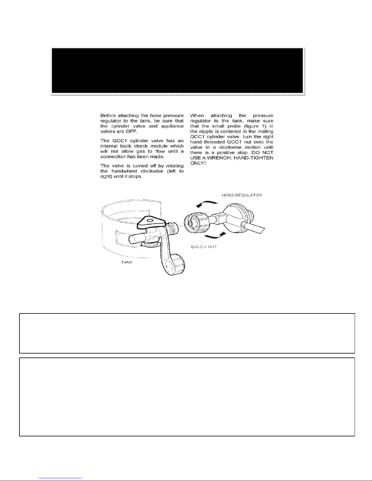
UrbanFire UF -4- User manual

1 | P a g e
WARNING: If the information in this manual is not followed exactly, a fire or explosion may
result causing property damage, personal injury, or loss of life.
For your safety
Do not store or use gasoline or other flammable vapors and liquids in the vicinity of this or any other
appliance.
What to do if you smell gas
sDo not try to light any appliance.
sDo not touch any electrical switch; do not use any phone in your building.
sImmediately call your gas supplier from a neighbor’s phone. Follow the gas supplier’s
instructions.
sIf you cannot reach your gas supplier, call the fire department.
Installation and service must be performed by a qualified installer, service agency or the gas
supplier.
URBAN FIRE -4-
Propane / Natural Gas
Outdoor Gas Fireplace
Installation and Operating Instructions
WARNING: Improper installation, adjustment, alteration, service or maintenance can cause
injury or property damage. Read the installation, operating and maintenance instructions
thoroughly before installing or servicing this equipment.
WARNING: For Outdoor Use Only.
Retain this manual forfuture reference
Certified by the CSA
(Canadian Standards Association)
#3!53RD%D
/UTDOOR'AS&IREPLACE
#'!#2
(UFF2D!TLANTA'! ,/#!, 4%!+
INFO AUTHENTEAKCOM WWWAUTHENTEAKCOM &OLLOWUS AUTHENTEAK ,IKEAUTHENTEAK

2 | P a g e
Table of Contents
INTRODUCTION ....................................................................................
Specifications ......................................................................................... 3
Dimensions & Installation Codes ............................................................ 4
General Safety........................................................................................ 5
OPERATION ..........................................................................................
Lighting Instructions ............................................................................... 6
LP Gas Safety Information ..................................................................... 7
LP Gas Cylinder Connection................................................................... 8
Leak Testing........................................................................................... 9
INSTALLATION ....................................................................................
Installation & Safety Notes ..................................................................... 10
Initial Firing ............................................................................................. 11
Minimum Clearances ............................................................................. 11
Battery & Glass Installation..................................................................... 12
Glass Placement .................................................................................... 13
Natural Gas Conversion….….……………………………………………… 14 & 15
MAINTENANCE.....................................................................................
Maintenance Safety ................................................................................ 16
Recommended Service ......................................................................... 16
Burner Cleaning ..................................................................................... 16
Trouble Shooting .................................................................................... 17
Replacement Parts ................................................................................. 18
Warranty ................................................................................................ 19 & 20
Urban Fire Corp.
103 South Belair Drive
Woodbridge, Ontario,
L4H 2N4
Canada 1-888-337-4989

3 | P a g e
1.0 INTRODUCTION
1.1 SPECIFICATIONS
TABLE 1
ITEM PROPANE (LPG)
INPUT: Hi 42,000 Btu/hr (12.30 kW)
INPUT: Lo 30,000 Btu/hr (8.79 kW)
MAXIMUM GAS INLET
SUPPLY PRESSURE:
Minimum LPG
11” w.c. (2.74 kPa)
Minimum NG
7” w.c (1.744 kPa)
AIR SHUTTER
SETTING
Adjustable from fully closed
to fully open
ORIFICE SIZE: @ 0-2000’
# 49 DMS LPG
# 34 DMS NG
Clearances to combustibles
Sides:
Back:
Floor:
Ceiling:
18” (45.7 cm)
18” (45.7 cm)
0*
72” (183 cm)
* Urban Fire -4- can be placed on a combustible base.

4 | P a g e
APPLIANCE DIMENSIONS
Figure 1
URBAN FIRE -2-
INSTALLATION CODES
Installation must conform to local codes or in the absence of local codes, installation
must conform to the National Fuel Gas Code, ANSI Z233. 1, or the current CAN/CGA
B149.05 Installation Codes. In the state of Massachusetts, this product can only be
installed by a licensed plumber or a licensed gas fitter. Failure to comply will void the
warranty.
570 x 570 x 727mm
22.44”!x!22.44”!x!28.62”!
The!appliance!and!its!individual!shutoff!valve!must!be!disconnected!from!the!gas!supply!
piping!system!during!any!pressure!testing!of!that!system!at!test!pressures!in!excess!of!!
1
/2!!psi!
(3.5!kPa).!
!
The!appliance!must!be!isolated!from!the!gas!supply!piping!system!by!closing!its!individual!
manual!shutoff!valve!during!any!pressure!testing!of!the!gas!supply!piping!system!at!test!
pressures!equal!to!or!less!than!
1
/2!psi!(3.5!kPa).!

5 | P a g e
GENERAL SAFETY
!Solid fuels shall not be burned in this fireplace.
!Keep the appliance area clear and free from combustible materials, gasoline and other
flammable vapors and liquids.
!Inspect the burner prior to each use, if the burner is damaged it must be replaced prior to use.
NOTE: Use only with burner part# UFP 1-02-1
!Inspect the pilot prior to each use, if the pilot is damaged, plugged or does not light, replace
damaged components prior to use.
!Do not use this appliance if any part has been under water. Immediately call a qualified
service technician to inspect the appliance and to replace any part of the control system and
any gas control which has been under water.
!Do not locate the fireplace in a pathway where people may trip into or fall into fireplace.
Do not locate fireplace in areas where it can be subjected to accidental damage.
!Children and adults should be alerted to the hazards of high surface temperature and
should stay away to avoid burns or clothing ignition.
!Young children should be carefully supervised when they are in the area of the
appliance. Keep cover of the fireplace secured on the appliance when not it use
to prevent children from playing, touching or eating the tempered glass.
!Clothing or other flammable material should not be hung from the appliance or
placed near the appliance.
!Any guard or other protective device removed for servicing the appliance must be
replaced prior to operating the appliance.
!Installation and repair should be done by a qualified service person. The appliance
should be inspected before use and at least annually by a qualified service person.
More frequent cleaning may be required as necessary. It is imperative that control
compartments, burners and circulating air passageways of the appliance be kept
clean.

Page 6
WARNING:!!Cover!must!be!removed!when!burner!is!in!operation.!
This!appliance!is!equipped!with!a!piezo!electric!ignition!device.!!Be!
aware!and!look!for!proof!of!ignition!spark.!!If!there!is!not!ignition!
spark!replace!piezo!ignitor!device!–OR"!light!pilot!manually.!
!!!

Page 7
The!specific!size!of!cylinder(s)!to!be!used!with!this!gas!fireplace!is!
recommended!not!to!be!below!or!exceed!20!lbs.!(9!kg)!capacity.!!Ensure!
cylinder!is!secured,!upright,!on!a!level!non"combustible!base.!
!
If!a!larger!TC!or!DOT!cylinder!is!to!be!used.!!Ensure!that!the!cylinder!is!safely!
secured,!upright!on!a!non"combustible!base,!located!a!minimum!of!10ft!from!
the!fireplace!and!in!a!ventilated!space.!!
!
Do!not!place!a!propane!cylinder!for!use!with!this!appliance!on!a!non"
combustible!base!"!even!snow.!!Snow!around!the!base!of!the!cylinder!foot!
ring!could!melt!and!the!cylinder!could!fall!over!delivering!liquid!propane!to!
the!unit.!
!
Do!not!connect,!activate!or!disconnect!this!fireplace!to!a!propane!cylinder!
anytime!while!consuming!alcohol.!!Failure!to!do!so!could!result!in!fire!causing!
bodily!harm!or!loss!of!life.!
Inspect!the!hose!assembly!for!
damage!prior!to!each!use.!If!the!
hose!is!damaged!or!there!are!signs!
of!excessive!abrasion!or!wear!
replace!the!hose.!
!
Use!only!the!pressure!regulator!and!
hose!assembly!supplied!with!the!
appliance.!Replace!the!regulator!hose!
assembly!only!with!part!number!UFP!
LP12"08!these!are!available!only!from!
a
pp
roved!dealer !"OR"Urban!Fire.!!

Page 8
LP GAS CYLINDER INSTALLATION
Tank Stabilizer
The LP cylinder must include a collar to protect the cylinder valve.
The cylinder supply system must be arranged for vapor withdrawal. This appliance uses a “Type 1”
cylinder connection device. See above for proper connection instructions.
When disconnecting and removing the gas cylinder, from the appliance, always be sure to adhere to
the following items:
!Check that the gas control valve is off at the appliance and ensure the valve on the cylinder is
turned off before disconnecting the gas line from the cylinder.
!Never smoke or have an open flame in the vicinity of the gas appliance or gas cylinder.
!When connection a new gas supply cylinder, be sure to tighten all connections and leak test
the connections with a soapy water solution.
Figure!1
LP!GAS!CYLINDER!CONNECTION!

Page 9
How to Leak Test Your Appliance
!Mix a solution of liquid soap and water in a small container. 50% soap and 50% water.
!Make sure that the gas supply is turned on. For LP gas appliances make sure that the valve on
the gas cylinder is turned on.
!Ensure that the gas control valve on the appliance is in the “OFF” position.
!Use a spray bottle or a small brush and liberally apply the solution to the gas line and to each
connection.
!If bubbles form this means that there is a leak is present.
!Tighten any connections that may be loose and leak test again.
!If no more leaks are found use the appliance.
!If leaks persist and cannot be stopped turn off the gas supply and contact your distributor or local
gas service technician for assistance.
!To check for leaks on the hose, soak cloth with soap and water solution. Rub gas line hose
from end to end. If bubbles appear, identify leak and replace hose before next use.
!WARNING: Do not use an open flame to test for gas leaks.

Page 10
INSTALLATION & SAFETY NOTES
Read all instructions before starting installation and follow them carefully during installation to ensure
maximum benefit and safety. Failure to follow these instructions will void your warranty and may
present a fire hazard. See the warranty at the back of this manual for disclaimers regarding improper
installation. This outdoor fireplace and its components are tested and safe when installed in
accordance with this installation manual.
UNPACKING
Please check the appliance carefully for any damaged or missing components. Report any problems
to your dealer within 30 days of purchase.
MINIMUM CLEARANCES
The minimum clearance to combustibles for the sides is 18” and the top is 72”.
This outdoor fireplace is suitable for installation on a combustible surface.
Clearances are in accordance with local installation codes and the requirements of the gas
supplier.

Page 11
INITIAL FIRING
When lit for the first time, the appliance may emit an odor resulting from evaporation of paint and
lubricants used in the manufacturing process. This is normal and will subside after the unit has run
for an hour or so.
MANIFOLD PRESSURE REGULATOR ADJUSTMENT
The manifold pressure regulator controls gas input and flame height, and is pre-adjusted at the
factory. No further adjustment is required.
PRIMARY AIR ADJUSTMENT
Aeration is factory set but may need adjustment for altitude or movement during shipping. The
adjustment for the air shutter is found on the mixing tube which is located underneath your appliance.
Loosen the screw which holds the aeration adjustment shutter in place and rotate the adjustment
shutter to increase or decrease primary air and tighten the screw. Increasing the primary air will cause
the flame to appear more transparent and blue. Decreasing the primary air will cause the flames to
appear more yellow or orange. Evaluate the aeration only after the unit has warmed up
approximately 15 minutes. If the unit shows signs of carbon build up increasing the primary air
should alleviate this problem.
Caution: Parts requiring adjustment during operation may be hot.
NOTE: WHEN RUNNING NATURAL GAS – The primary air shutter should be adjusted to the
lowest setting (decrease primary air) to get a more yellow natural flame.
Aeration adjustment is important for the correct functioning of the appliance. Carbon build up, flame
lifting or any malfunction due to improper aeration adjustment during installation is not covered under
the factory warranty.

Page 12

Page 13

Page 14
4.!Remove!orifice!by!removing!support!
nut!attached!to!bracket.!
5.!Remove!LPG!orifice!tip!and!replace!
with!NG!(larger!opening)!orifice!tip.!
6.!Reattach!converted!orifice!to!
supporting!bracket!with!nut.!!Leak!check!
with!a!soap!and!water!solution.!!
1.!Replace!LPG!Pilot!with!Natural!Gas!
Pilot.!!Using!two!adjustable!wrenches!
disconnect!propane!hose,!3/8!flare!fitting!
and!propane!pilot!regulator!as!shown!
above.!!Using!gas!pipe!compound,!attach!
Natural!Gas!pilot!regulator!and!3/8!flare!
fitting.!!!!!
Pilot Regulator & Hose

Page 15
7.!!Take!protective!cover!box!off!of!the!pilot!assembly!by!
removing!the!mounting!screws!located!on!the!top!side!of!
the!pilot!assembly.!!This!will!allow!you!to!access!the!pilot!
assembly.!!Take!an!adjustable!wrench!and!loosen!the!pilot!
flame!counter!clockwise.!!!This!will!allow!you!access!to!the!
pilots’!orifice.!!8.!!Slide!tab!to!Natural!Gas!position!(slightly!
larger!hole).!!!Re"fasten!pilot!flame!with!wrench!clockwise.!!
Soap!check.!

Page 16
MAINTENANCE
MAINTENANCE SAFETY
Turn off the gas to the main burner and allow the fireplace to cool for 30 minutes before
servicing.
Service and repair should be done by a qualified service person. The appliance should be inspected
before use and at least annually by a qualified service technician. It is important that the access door
compartment and burner be kept clean to provide for adequate combustion and ventilation airflow.
Do not substitute materials or use components other than factory supplied.
RECOMMENDED SERVICE
Visually check the burner flame occasionally.
Have the appliance inspected annually by a professional service technician.
Clean the appliance regularly.
BURNER CLEANING
Periodic cleaning is necessary for proper operation.
Remove the orifice, and check that the burner orifice is clean. If the orifice is plugged, disassembly
may be required to remove any foreign material from the orifice or tubing.
Visually inspect the burner before each use of the appliance. Inspect the burner Brush or blow away
any dust, glass, or foreign debris from burner holes. If the burner is found to be corroded or
damaged, the burner must be replaced prior to the appliance being put into operation.
.
.

Page 1
7
TROUBLE SHOOTING
SYMPTOM POSSIBLE CAUSE CORRECTIVE ACTION
Burner will not light after
repeated triggering of the
ignition button
A. No spark at electrode
1. Improper ignition 1. Check to ensure battery is installed and
has power at igniter.
2. Poor connections at ignition
electrode
2. Reconnect orange electrode wire at back
of igniter.
3. Broken ceramic cover on
ignition electrode
3. Replace pilot assembly
4. Pilot wont light 4. Remove glass around pilot cover
5. Defective igniter 5. Ensure battery is installed. Replace igniter
6. Won’t stay lit. 6. Loosen thermocouple copper line
that comes from the pilot and
connects into the control valve.
Retighten only finger tight and then
1/8 turn with wrench.
7. Whistle noise from pilot 7. Ensure pilot is converted to correct
gas.
8. Whistle noise from burner tube 8. Point burner tube below burner
outlet holes
B. No gas or low gas pressure
1. Gas line shut off 1. Turn on shut-off valves
2. Air in gas lines 2. Purge gas lines
3. Gas lines may not be
connected
3. Connect all gas lines
4. Low pressure may be caused
by bent line
4. Check for a kinked line
Burner will not light A. Valve / Switches
1. Valve control off 1. Turn to “ON” position
2. Blockage at the burner (line,
orifice, or ports)
2. Check and clean

Page 18
URBAN FIRE -2- Replacement Parts
When requesting service or replacement parts for your unit, please
provide model name and serial number. All parts listed above may
be ordered from an authorized dealer -or- by calling Urban Fire
customer service at 1
-
888
-
337
-
4989 x 3.

Page 19
Please!register!your!product!
immediately!at!www.urbanfire.ca!or!
call!1"888"337"4989!x!3!

Page 20
Table of contents
Other UrbanFire Outdoor Fireplace manuals
Popular Outdoor Fireplace manuals by other brands

Camp Chef
Camp Chef REDWOOD Warning & instruction booklet

pleasant hearth
pleasant hearth OFW155H manual

Red Fire
Red Fire Juva 81024 manual

Outsunny
Outsunny Fire pit Assembly instructions

Outdoor GreatRoom Company
Outdoor GreatRoom Company Kenwood Dining Table installation instructions

PYROMANIA
PYROMANIA GENESIS Feature manual

Bull
Bull 31044 operating instructions

Superior Fireplaces
Superior Fireplaces VRE4536WS Installation and operation instruction manual

Paloform
Paloform MISO CIR-18 installation manual

Outsunny
Outsunny 867-123V00 Assembly instruction

Mayer Barbecue
Mayer Barbecue HEIZA MGK-150 Assembly instructions

Bond
Bond Belden owner's manual