urbansolar RMS-F Series User manual

REV 14-10-24
PV-Shelter
RMSxxF
Installation & Operation Manual
Transit Solar-powered LED Lighting System

Installation & Operation Manual
REV 14-10-24 Page 2 of 19
PV-Shelter RMSxxF Series
Contents
Page 3 ................................................. - Introduction
Page 4 ................................................. - How it Works
Page 5 ................................................. - Data Logging /Retrieval
- Assembly
Page 9 ................................................. - Installation and Assembly
Page 15 ................................................. - Troubleshooting
Page 16 ................................................. - Maintenance/ Product Care
- Batteries
- Contact and Re-order Information
Page 17 ................................................. - Appendix A: RMSxxF Exploded View
Page 18 ................................................. - Appendix B: RMSxxF Exploded View
Page 19 ................................................. - Appendix C: Warranty

Installation & Operation Manual
REV 14-10-24 Page 3 of 19
PV-Shelter RMSxxF Series
Introduction
The Urban Solar Corporation RMSxxF stand alone solar powered LED lighting system has been
designed specically to meet the requirements for lighting the barrel roof type transit shelter. The
system has been engineered to integrate with the shelter’s mechanical design in order to provide an
aesthetic look and a very simple installation procedure.
Currently there are four sizes available – the RMS30F, RMS60F, RMS90F and the RMS50F. The
dierent models are identical except for solar array size. The size required depends on the local
solar conditions, required lighting levels and duration as well as shelter construction.
Safety Information
NOTICE:
Thoroughly read these instructions and familiarize yourself with the equipment before installing,
operating, servicing or maintaining it. The following message warns of potential hazards and oers
instructions to avoid them.
This equipment should be installed, operated, serviced, and maintained only by qualied personnel.
A qualied person is one who has skills and knowledge related to the construction and operation
of this equipment and its installation, and has received safety training to recognize and avoid the
hazards involved.

Installation & Operation Manual
REV 14-10-24 Page 4 of 19
PV-Shelter RMSxxF Series
How it works
The RMS series shelter lighting system provides lighting using state of the art LED luminaires,
batteries and solar panels, integrated with an intelligent programmable energy control module
(ECM). Electricity generated by the solar panels is directed to the ECM which regulates the charging
of the battery bank and switches on the power to the LEDs. The ECM is factory programmed to
provide variable calendar based lighting proles (on time duration and intensity) to match the
available solar insolation and user preferences. The main system components are described below:
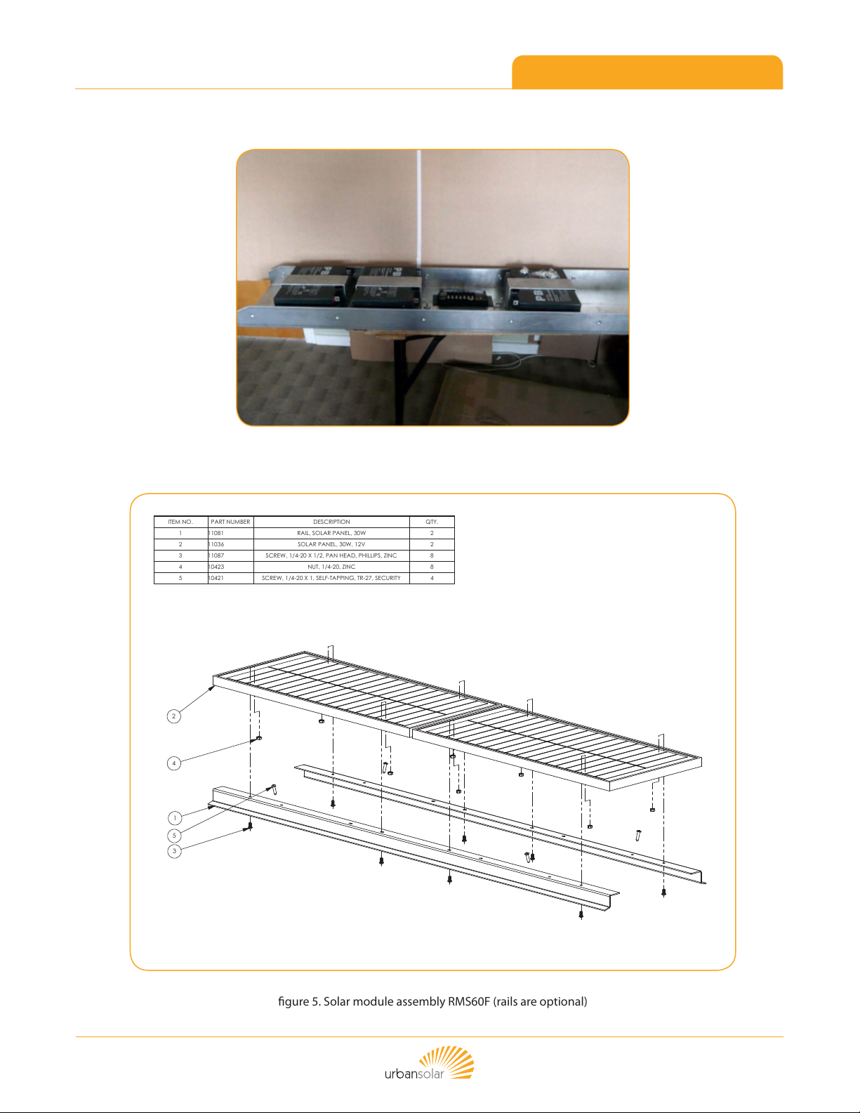
PV Array (solar module)
The PV array consists of one, two, or three 30W solar modules mounted to a metal framework.
Alternatively, a single 50W solar module can be used for some applications. The solar panel array
size is selected to provide enough solar charging for the system to operate dusk till dawn, at a
specic brightness level, year round at a given geographical location.
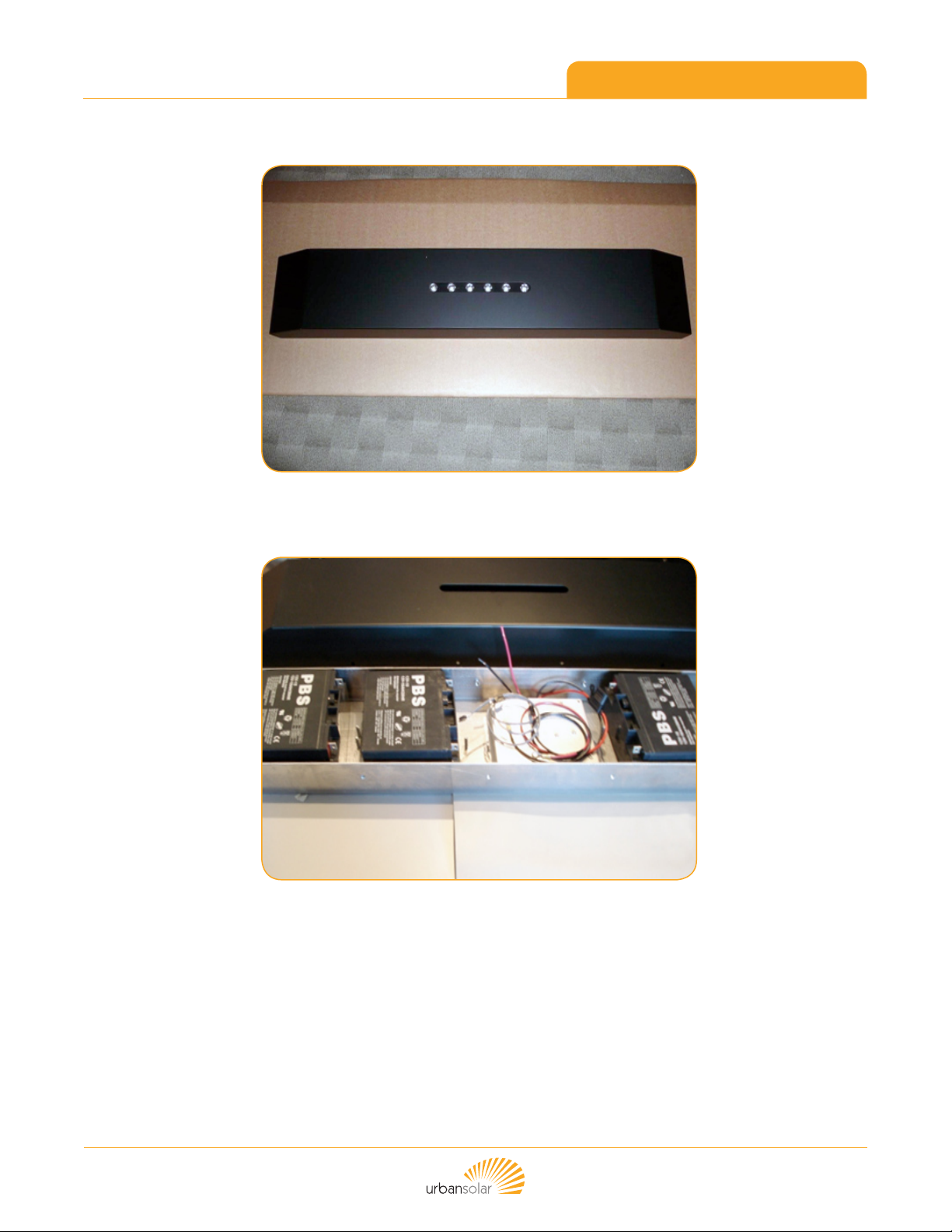
Batteries
The battery bank is composed of two or three 18 amp-hour 12 Volt cells. The batteries are sealed,
lead acid, rechargeable, and provide a minimum of 5 days autonomy (i.e. the system could operate
for a minimum of 5 days with absolutely no solar charging – for example during heavy snowfall).
Luminaires
The LED luminaires contain high power white LEDs. The luminaires are driven well below their
maximum power rating to increase eciency and extend the already long life.
ECM
The Energy Control Module is the central control of the lighting system. It controls battery
charging and regulates the power to the LED luminaires. The ECM also monitors the system
performance to ensure the batteries will not be damaged by over charging, and will turn o the
LEDs if the battery voltage falls below the low voltage disconnect (LVD) setting. Once the
batteries have been suciently charged above the LVD, the ECM will turn the LEDs back on
again. The ECM is factory programmed for a specic operation prole based on the customer
requirements for LED on-time and brightness level, and depends on the geographical location
and solar array size. Using a calendar based approach, the LED light levels and on-times can
be optimized for maximum performance year round.
Operating Prole
The RMSxxF has a built in programmable energy control module (ECM). The standard operating
prole has luminaires automatically turning on after dusk at full brightness, and turning o at dawn
– this is the dusk till dawn (D/D) prole. However, in some locations, and depending on the season,
there may be insucient sunlight to support the D/D prole all year long. Therefore, the RMSxxF
is pre-programmed at the factory to set a calendar based operating prole to maximize the light
intensity and duration based on NASA solar insolation data for the region.
For example, an RMS30F in Seattle might be programmed for D/D lighting for the months of
May through September, and then a shorter lighting duration and/or lower intensity from October
through April (for example, dusk+6hrs/dawn-2hrs, at 75% intensity). Since the programming
is calendar based, the lighting levels and durations can be adjusted and optimized on any
time interval.

Installation & Operation Manual
REV 14-10-24 Page 5 of 19
PV-Shelter RMSxxF Series
Data Logging /Retrieval
The ECM keeps a daily log of critical operating parameters such as battery voltage, solar panel and
LED Current. This data can be retrieved in the eld in order to assess the system performance. This
gives engineering sta at Urban Solar Corp the ability to continuously evaluate performance of the
solar charging capabilities and compare real time performance to the modeled simulations.
Assembly
Typically the RMSxxF is shipped completely assembled and ready for installation. All that is
required is to install the power module to the shelter ceiling, run the wiring harnesses and mount
the solar array to the roof of the shelter. The batteries may be shipped separately and can be wired
during the installation process. For wiring details refer to the wiring schematic.
DRAWN BY
David Hanke
DATE
07/04/2009
REVISION
D HANKE
Urban Solar
(T) 778-430-5516 (F)778-430-5517
TITLE
SIZE
4041 Elise Place
± .0005
± .005
.XXXX
1 OF 1
RMS 60F concept
B
B
PROPRIETARY
, BC, Canada, V8X 4K1Victoria
DOCUMENT MAY BE REPRODUCED STORED IN A
RETRIEVAL SYSTEM, OR TRANSMITTED IN ANY
TOLERANCES APPLY AS SHOWN BELOW
FORM, WITHOUT THE WRITTEN PERMISSION OF
INTERPRET DIMENSIONS AND TOLERANCES
INCHES
PER ASME Y14.100-2000
Urban Solar
DO NOT SCALE DRAWING
± .1
± .01
.XXX
ANGLES
UNLESS OTHERWISE SPECIFIED
THIRD ANGLE PROJECTION DATEDESIGNED BY DRAWING NO
SHEET
CAD REFERENCE
10430
COPYRIGHT © 2008 BY
Urban Solar Corp., Victoria, BC, Canada
ALL RIGHTS RESERVED. NO PART OF THIS
.X
.XX
DECIMALS
18/02/2009
gure 1. RMSxxF components

Installation & Operation Manual
REV 14-10-24 Page 6 of 19
PV-Shelter RMSxxF Series
gure 2. Power module
gure 3. Power Module with LID removed
(shown with ECM and batteries)

Installation & Operation Manual
REV 14-10-24 Page 7 of 19
PV-Shelter RMSxxF Series
gure 4. Batteries and brackets (3)
PAGE
DRAWN BY
D HANKE
DATE
07/07/2012
REVISION
(T) 778-430-5516 (F)778-430-5517
TITLE
6N6, BC, Canada, V8ZVictoria
Commerce Circle4211
Urban Solar
C
11092
PERMISSION OF Urban Solar
DRAWING NO
PROPRIETARY
COPYRIGHT © 2008 BY
Urban Solar Corp., Victoria, BC, Canada
ALL RIGHTS RESERVED. NO PART OF THIS DOCUMENT MAY
BE REPRODUCED STORED IN A RETRIEVAL SYSTEM, OR
TRANSMITTED IN ANY FORM, WITHOUT THE WRITTEN
gure 5. Solar module assembly RMS60F (rails are optional)

Installation & Operation Manual
REV 14-10-24 Page 8 of 19
PV-Shelter RMSxxF Series
gure 6. ECM with Solar, LED and battery connections
gure 7. Battery jumper harnesses

Installation & Operation Manual
REV 14-10-24 Page 9 of 19
PV-Shelter RMSxxF Series
Installation and Assembly
Please read the entire installation procedure before starting as the order of operations is optional.1.
Since every shelter is dierent, attaching the solar panels and power module to the shelter is the
responsibility of the contractor on-site. Urban Solar provides basic hardware and brackets or rails to
secure the solar panel to the roof. These require screwing into or bolting through the roof structure.
The solar panel and LED xture cables require an entry way into the shelter as well. The contractor
shall provide an appropriate liquid tight cord grip for this purpose. The installer will need to ensure
any roof penetrations are sealed against water. There shall be no exposed wiring on the roof or interior
of the shelter, and the contractor must use appropriate conduit and electrical connectors in order to
provide a professional, reliable, and aesthetic installation. If there is any question as to the acceptability
of the installation method, the contractor shall consult with Urban Solar support sta.
Determine the mounting location on the ceiling of the shelter. The power module base should be2.
positioned so that it can be secured to the shelter roof ribs near each end – i.e. centered on two roof ribs.
Typically the module will be positioned at the center of the shelter. Using appropriate hardware (TEK
screw), mount the power module base to the ceiling and ensure it is secured with a minimum of four (4)
screws fastened directly through the roof ribs. Pilot holes will likely need to be drilled in the power
module base and roof ribs – use a 13/64 drill bit for the pilot holes.

Installation & Operation Manual
REV 14-10-24 Page 10 of 19
PV-Shelter RMSxxF Series
gure 8.
gure 9.
Note – the following steps (4-7) can be performed before the module is mounted to the shelter ceiling as it
may be easier to do in the shop – it is at the discretion of the installation crew. It will make mounting to
power module to the ceiling of the shelter more dicult because of the weight of the batteries, but makes
battery wiring much easier.

Installation & Operation Manual
REV 14-10-24 Page 11 of 19
PV-Shelter RMSxxF Series
Insert batteries in to the power module and secure with the battery hold down straps provided.3.
gure 10.
Be cautious when handling the battery pack. It is capable of generating hazardous short-circuit currents.
Remove all jewelry (bracelets, metal-strap watches, rings) before attempting to handle or disassemble the
battery pack. Contact Urban Solar if further instruction is required.
USE EXTREME CAUTION WHEN INSTALLING BATTERY HARNESSES. ALWAYS WEAR INSULATING GLOVES
WHEN CONNECTING BATTERIES. AVOID CONTACT OF FREE POSITIVE RING TERMINALS WITH NEGATIVE
TERMINALS OF BATTERY OR ANY PART OF THE CHASSIS
gure 11. RMS60F wiring diagram

Installation & Operation Manual
REV 14-10-24 Page 12 of 19
PV-Shelter RMSxxF Series
Battery wiring – batteries are wired in PARALLEL. Use the 2 black jumper cables to connect all of the black4.
terminals together, and use the 2 red jumper cables to connect all the red terminals together.
Attach the black main negative battery power cable coming from the ECM to one of the negative battery5.
terminals.
Remove the inline fuse and attach the red fused main positive battery power cable coming from the ECM6.
to one of the positive battery terminals.
Use wire ties to tidy up wiring and tuck neatly out of the way.7.
Installed solar panel on shelter roof.
gure 12. Installed solar panel on shelter roof
Determine solar panel positioning then mark and drill holes for mounting to the shelter roof ribs.8.
Drill a hole through the roof for routing the solar panel wiring into the power module. The hole should9.
line up with one of the larger wire feed through holes in the power module base.
Route the solar panel wires through to the power module then secure panels to the roof using security10.
screws provided.
Caution – do not short the solar panel positive leads to the negative leads or to any part of the metal work on
the chassis or shelter. Use electrical tape to insulate leads when routing solar panel wiring.
For the RMSxxF when there are two or more solar panels, the panels are wired in parallel. Connect both11.
positive solar leads to the positive (red) lead from the ECM as shown. Connect both negative solar leads to
the negative (black) lead from the ECM. Use marrettes (wire nuts) to make connections.
Hold the power module lid up and make the connection for the luminaire to the control module as shown.12.
Coil up any excess wiring and use wire wraps or zip ties to neaten up and tuck away all wiring.13.

Installation & Operation Manual
REV 14-10-24 Page 13 of 19
PV-Shelter RMSxxF Series
Power-Up and Final Testing
The nal step is to apply power to the unit by installing the inline fuse on the positive battery lead. Upon14.
power-up, the LEDs should blink briey and turn o if the solar panel is in daylight; if installing at night,
the LEDs will blink and then turn on.
Please note: If the solar panel is covered or disconnected during day-time the LEDs will not turn on at full
power. The default day-time brightness level is 10%. The LEDs will turn on at full power only during
night-time operation.
gure 13. ECM is marked with a label
The RMSxxF also has a self-test feature that is activated by swiping a magnet
over the reed switch located inside the ECM. The ECM is marked with a label showing
where to swipe the magnet as shown
The self-test, when activated, will provide information on system health by ashing the LEDs in a
predetermined sequence. On activation the LEDs will ash 3 times quickly, pause, and then ash
slowly giving one to four ashes depending on the state of charge of the batteries. If the lights do
not ash the system requires troubleshooting – see manual.
1 ash 0- 25% battery system could fail soon or is in LVD
2 ash 25-50% battery caution, system might be under performing
3 ash 50-75% battery system is good
4 ash 75% or greater (100%) battery system is receiving optimal charging
The battery bank size and system load have been carefully selected to maintain the energy balance for the
specic solar region. Expect to see three or four ashes on the battery diagnostic test near the end of the
day. If there are 2 or less ashes the system could be under performing or not getting enough solar charg-
ing due to very poor weather, a poor solar site (shaded), or both.
Note: Install solar powered lighting system within 3 months of delivery. Sealed lead acid batteries will self
discharge in storage. It is recommended that installation occur as soon as possible after delivery to ensure
the maximum life cycle of batteries is recognized.
Swipe a magnet here to
activate self-test feature

Installation & Operation Manual
REV 14-10-24 Page 14 of 19
PV-Shelter RMSxxF Series
Battery warranty will be void for systems that are not installed within 6 months of delivery
by Urban Solar Corp.
Replace the power module lid and secure with Torx Security fasteners provided.15.
The RMSxxF installation process is now complete. The LEDs will turn on approximately
30 minutes after sunset.
gure 14. RMSxxF Power Module

Installation & Operation Manual
REV 14-10-24 Page 15 of 19
PV-Shelter RMSxxF Series
Troubleshooting
In the event the RMS30/60F fails to turn on after dark (or simulated darkness):
Check that the panel is completely dark. If there is a street-light directly overhead this can1.
sometimes provide enough light to simulate daytime. If you are using a cover to simulate
darkness ensure that the panel is completely covered and totally dark.
Open the power module lid, remove the fuse in the positive battery connect lead, and measure2.
the battery voltage across the battery terminals:
If the battery voltage is <11.0Volts contact Urban Solar Corp for assistance.3.
If the voltage is between 11.0 and 11.9V then the battery needs to be charged before the4.
lights will activate. When the battery voltage falls to less than 11.9V, the ECM protects the
battery from over-discharge by disconnecting power to the luminaires. Once the system has
had sucient time and sunlight to recharge and the battery voltage reaches 12.4 Volts, the
ECM will reconnect power to the luminaires, and the system will function normally. Charging
will occur naturally in the eld and the unit can be checked again after a few sunny days.
Alternatively a battery charger may be used – please consult Urban Solar Corp.
If the battery voltage is >11.9V the lights should activate.5.
Ensure the panel is in complete darkness. Remove the fuse from the positive lead of the battery6.
and check to make sure the fuse is not blown. Replace the fuse if required.
Remove the fuse and wait 10 seconds, then reconnect the fuse. If lights activate then the7.
problem is solved. Note - this can be repeated up to 5 times to “reboot” the ECM controller.
If the above steps do not restore normal operation, contact Urban Solar for assistance.8.

Installation & Operation Manual
REV 14-10-24 Page 16 of 19
PV-Shelter RMSxxF Series
Maintenance/ Product Care
Although the system is designed to be maintenance free, optimal performance requires
clean solar panels and lenses. Clean on an annual basis or as required. Use water and a
soft sponge or cloth for cleaning and a mild, non-abrasive cleaning agent for more stubborn
residue. Rinse well.
Batteries
Battery MSDS available upon request. Contact Urban Solar Corp
Be cautious when handling the battery pack. It is capable of generating hazardous short-circuit
currents. Remove all jewelry (bracelets, metal-strap watches, rings) before attempting to handle
or disassemble the battery pack. Contact Urban Solar if further instruction is required.
IMPORTANT MAINTENANCE NOTE!
Over time dirt and debris may collect on the solar module (panel). Excess dirt or grime will reduce
battery charging and thus can lead to premature battery failure and or lack of performance.
Urban Solar recommends at a minimum an annual cleaning of the solar module. Water and soap
are recommended rather than simply ‘spraying’ the solar panel. Please see manual or contact Urban
Solar for more information.
Consult your local municipal by-laws for information on recycling the cells.
DO NOT THROW THE CELLS IN THE GARBAGE!
Contact and Re-order Information
If you have any questions or feedback we would like to hear from you. Please visit our website or feel
Urban Solar (USA)
1880 SW Merlo Drive
Beaverton, OR, USA, 97006
Urban Solar (Can)
4211 Commerce Circle
Victoria, BC Canada, V8Z 6N6
www.solarlightingfortransit.com

Installation & Operation Manual
REV 14-10-24 Page 17 of 19
PV-Shelter RMSxxF Series
Appendix A: RMS60F - Exploded View
DRAWN BY
David Hanke
DATE
07/04/2009
REVISION
D HANKE
Urban Solar
(T) 778-430-5516 (F)778-430-5517
TITLE
SIZE
4041 Elise Place
± .0005
± .005
.XXXX
1 OF 1
RMS 60F concept
B
B
PROPRIETARY
, BC, Canada, V8X 4K1Victoria
DOCUMENT MAY BE REPRODUCED STORED IN A
RETRIEVAL SYSTEM, OR TRANSMITTED IN ANY
TOLERANCES APPLY AS SHOWN BELOW
FORM, WITHOUT THE WRITTEN PERMISSION OF
INTERPRET DIMENSIONS AND TOLERANCES
INCHES
PER ASME Y14.100-2000
Urban Solar
DO NOT SCALE DRAWING
± .1
± .01
.XXX
ANGLES
UNLESS OTHERWISE SPECIFIED
THIRD ANGLE PROJECTION DATEDESIGNED BY DRAWING NO
SHEET
CAD REFERENCE
10430
COPYRIGHT © 2008 BY
Urban Solar Corp., Victoria, BC, Canada
ALL RIGHTS RESERVED. NO PART OF THIS
.X
.XX
DECIMALS
18/02/2009
gure 15. RMS60F - Exploded View

Installation & Operation Manual
REV 14-10-24 Page 18 of 19
PV-Shelter RMSxxF Series
Appendix B: RMS60F Solar Panel - Exploded View
PAGE
DRAWN BY
D HANKE
DATE
07/07/2012
REVISION
(T) 778-430-5516 (F)778-430-5517
TITLE
6N6, BC, Canada, V8ZVictoria
Commerce Circle4211
Urban Solar
C
11092
PERMISSION OF Urban Solar
DRAWING NO
PROPRIETARY
COPYRIGHT © 2008 BY
Urban Solar Corp., Victoria, BC, Canada
ALL RIGHTS RESERVED. NO PART OF THIS DOCUMENT MAY
BE REPRODUCED STORED IN A RETRIEVAL SYSTEM, OR
TRANSMITTED IN ANY FORM, WITHOUT THE WRITTEN
gure 16. RMS60F Solar Panel

Installation & Operation Manual
REV 14-10-24 Page 19 of 19
PV-Shelter RMSxxF Series
Appendix C: Warranty
Urban Solar Corporation (“the manufacturer”) will warrant, for a period of ve (5) years from the
date of delivery that all Urban Solar Corp. solar-powered LED shelter lighting systems will comply
with published product specications. Date of delivery shall be dened as the day after the product
or system leaves the manufacturers facility. This warranty covers all parts for each entire lighting
system installed, excluding batteries, which have a prorated three (3) year warranty. No other
warranty is stated or implied. This warranty shall not be assigned without the express written
consent of the manufacturer.
The warranty on any replacement products will not extend beyond the ve years from original
installation date. Please note that the customer is responsible for return of defective products to
the manufacturer.
The manufacturer makes no warranties, expresses or implied concerning the goods furnished
hereunder other than they shall meet the manufacturer’s current sales specications. Any
recommendations made by manufacturer concerning the use, design or application of said
goods are believed reliable, but the manufacturer makes no warranty of results to be obtained.
The buyer assumes all responsibility and liability for loss or damage resulting from the handling
or use of said goods.
Prorated Battery Warranty
36 Month Prorated Battery Warranty
0 to 12 months 100% of the original battery purchase price will be refunded or applied
to the purchase of a new unit
13 to 24 months 50% of the original battery purchase price will be refunded or applied
to the purchase of a new unit
25 to 36 months 25% of the original battery purchase price will be refunded or applied
to the purchase of a new unit
Note:
Install solar powered lighting system within 3 months of delivery. Sealed lead acid batteries will self
discharge in storage. It is recommended that installation occur as soon as possible after delivery to
ensure the maximum life cycle of batteries is recognized.
Battery warranty will be void for systems that are not installed within
6 months of delivery by Urban Solar Corp.
Table of contents