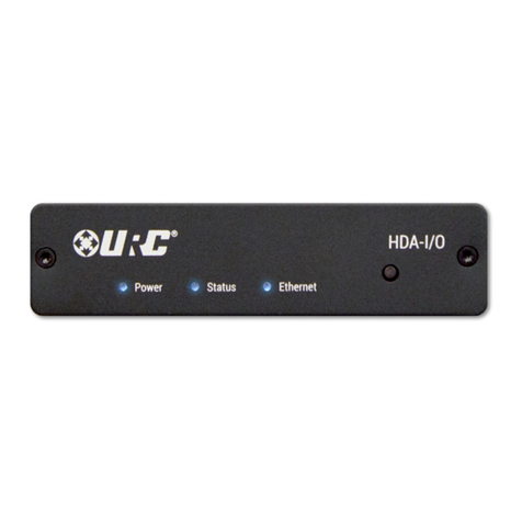
URC HDA-I/O User manual

HDA–I/O
Owner’s Manual
Total Control HDA-I/O
Owner’s Manual

Total Control HDA-I/O
Owner’s Manual
Rev 1.0
Table of Contents
Introducing the HDA-I/O
The HDA-I/O Single- one Amplifier is URC’s powerful and discrete amplifier!
This document highlights product features, LED status conditions, basic installation,
and general speaker wiring instructions.
Online Support:
Total Control is sold direct onl and must be installed/programmed b a certied
custom integrator.
End-User Support:
Visit the URC Home Page for product information, owner’s manuals, and support
contact information.
Contact Support:
Total Control is a URC product sold direct onl . For questions or assistance contact
our Custom Installer/Programmer.
My Installer/Programmer
Overview............................................................................................................................1
Parts & Pieces ..................................................................................................................2
Front Panel Descriptions ................................................................................................3
Rear Panel Description - Using as a Stream Injector ...............................................5
Rear Panel Description - Using as a Stream Receiver .............................................6
Installation Instructions..................................................................................................7
Network Setup..................................................................................................................9
HDA Modules ..................................................................................................................10
Specifications .................................................................................................................11
Limited Warranty Statement.........................................................................................11
Technical Suppor t
Toll Free: 800-904-0800
Main: 914-835-4484
techsupport@urc-automation.com
H o u r s : 9 : 0 0 a m - 5 : 0 0 p m E S T M - F

1
Total Control HDA-I/O
Owner’s Manual
Overview
URC’s HDA-I/O Stream Receiver/Injector creates or receives HDA audio streams
over the network. This device must be congured b a certified URC integrator to
function as either a Stream Injector or Stream Receiver.
AsaStream Injector, this device distributes any connected audio source (digital or
analog) over the network to any available HDA controlled zone.
AsaStream Receiver, the HDA-I/O connects to our favorite 3rd party audio device
and provides it with access to all HDA audio streams on the network.
HDA products are NOT compatible with URC’s legac Total Control ampliers (DMS).
Features & Benefits:
• Stream Receiver or Stream Injector Capabilities: Congured via URC
software, the HDA-I/O can receive or transmit HDA audio streams over the
local network.
• HDA Audio Streams: As a Stream Injector, this device distributes an
connected audio source to an available HDA controlled audio zone.
• Source Sharing: An zone controlled via an HDA amplier or I/O device has
access to the s stem’s HDA Audio Streams.
• Flexible one Linking: When connected to a 3rd part audio device as a
Stream Receiver, the HDA-I/O can link that 3rd part zone with an other HDA
controlled zone.
• Integrated Audio Sensor: Each available input on the HDA-I/O has built-
in audio sensing capabilities. These sensors can be used to trigger
programmed events or activities.
• one Input Ducking: The HDA-I/O has the abilit to “fade in” an audio
input over the currentl selected audio input. The perfect solution to brie
lower the volume on the current source to make an audio announcement or
doorbell chime.
• Power Configuration Options: The HDA-I/O can be powered via PoE or
the supplied 12VDC adapter.
2
Total Control HDA-I/O
Owner’s Manual
Parts & Pieces
Included with the HDA-I/O are the following:

3
Total Control HDA-I/O
Owner’s Manual
Front Panel Descriptions
There are three (3) LEDs on the front panel of the HDA-IO:
1. Power LED: Indicates one (1) of the following:
• Solid Blue: Power has been applied to the device and it has
successfull initialized.
• Off: Power has been removed from the device.
2. Status LED: Indicates one (1) of the following:
• Solid Blue: The device has been programmed with Total Control software
and is read for operation.
• Blinking Blue: The device is receiving a download from the Total Control
programming software.
• Blinking Green: The device is receiving a firmware upgrade, this light
continues to blink until the update is full applied.
• Off: The device has not been programmed with Total Control software.
1
2

4
Total Control HDA-I/O
Owner’s Manual
3. Ethernet LED: Indicates one (1) of the following:
• Solid Blue: The device has received an IP address from the local network.
• Blinking Blue: The device is connected to the local network; however, it
has not received an IP address.
• Off: The device is not connected to the local network.
4. Reset Button: There are two (2) wa s to press this button:
• Single Press: Tap the Reset button to power c cle the device.
• Factory Reset: Press-n-hold the Reset button for 10 seconds or more.
This option cannot be reversed, once the device has been factor defaulted
it requires re-programming.
34

5
Total Control HDA-I/O
Owner’s Manual
Rear Panel Description - Using as a Stream Injector
Below are the available connections on the rear of the HDA-IO:
1. DC IN: Connect the supplied 12VDC adapter to this port to power the
HDA-IO.
2. LAN: Full Duplex Gigabit LAN ONLY, for audio streaming and zone control
(Wi-Fi NOT supported, device must be hard-lined to the network).
3. 12 VDC CTRL: Mono 3.5mm connector capable of suppl ing 150mA of current.
4. Analog/Digital Inputs: Both of the following inputs can be used to
provide HDA “high-definition” audio streams. Onl one input can
be in use at an given time.
• Analog - Unbalanced RCA
• Toslink (Optical)
• Digital Coax
1
2
3
4

6
Total Control HDA-I/O
Owner’s Manual
Rear Panel Description - Using as a Stream Receiver
Below are the available connections on the rear of the HDA-IO:
1. DC IN: Connect the supplied 12VDC adapter to this port to power the
HDA-IO.
2. LAN: Full Duplex Gigabit LAN ONLY, for audio streaming and zone control
(Wi-Fi NOT supported, device must be hard-lined to the network).
3. 12 VDC CTRL: Mono 3.5mm connector capable of suppl ing 150mA of current.
4. Analog/Digital Outputs: All three (3) available outputs can be used. The
HDA-IO as a stream receiver provides 3rd part audio zones with access to
audio sources streaming via HDA.
• Analog - RCA St le
• Toslink (Optical)
• Digital Coax
1
2
3
4

7
Total Control HDA-I/O
Owner’s Manual
Installation Instructions
The HDA-IO amplifier is supplied with two (2) “L” shaped brackets for mounting
on the wall or secure vertical surface.
1. Insert the supplied screws into the two (2) ke ed slots on the L shaped bracket
(as displa ed on the image at the right).
This L shaped bracket can be pre-installed and the HDA-IO amplifier can be
inserted afterwards.
2. Insert the supplied screws into the four (4) ke ed slots for wall mounting.
Ke hole Diameter: 0.48”/12.5mm
1
2

8
Total Control HDA-I/O
Owner’s Manual
3. Assure that all screws have been installed securel . 3

9
Total Control HDA-I/O
Owner’s Manual
Network Setup
When using more than one (1) HDA devices, URC’s HDA-SW5 Network Switch is
REQUIRED on the local network.
For more information of the HDA-SW5 Network Switch, please refer to the
HDA-SW5 Owner’s Manual.
Although 3rd Part AVB switches ma be utilized, the are not supported b
URC’s Technical Support team.
Connecting the HDA-I/O to the Network
1. Connect an ethernet cable to an available LAN port on the head-end
network switch.
If no switch is connected to the network then connect the ethernet cable to
an available LAN port on the local router (Luxul preferred).
2. Connect the ethernet cable from the previous step to an available LAN port
on the HDA-SW5.
3. Connect another ethernet cable to an available LAN port on the
HDA-SW5 Network Switch.
4. Connect the ethernet cable from the previous step to the ethernet port
found at the rear of the HDA-IO (page 5).
5. Configure the HDA-IO to a DHCP/MAC reservation within the local router
and program the device into the new or existing Total Control s stem.
Acertified URC integrator is REQUIRED to integrate the HDA-IO into a
new or existing Total Control s stem.
1 2
HDA-I/O
Local Router HDA-SW5 Network Switch

10
Total Control HDA-I/O
Owner’s Manual
HDA Modules
URC’s HDA line of products contains several two-way modules that are accessible
from an graphical user interface.
These modules serve a variet of residential and commercial applications providing
end-users with advanced functionalit directl from an URC interface.
For specific instructions on how to use these HDA modules, please refer to the
HDA User’s Guide.
The following modules are supported b the HDA-I/O Multi- one Amplifier:
• Room Volume Module
• Room / one EQ Module
• Volume Mixer Module
• Announcement Module
• Input Status
• Amplifier Status
• one Status
Room / Zone Status
Amplifier Status
Room / Zone EQ
Announcements
Not all HDA modules are displa ed
at the right, for full details on how
these modules, refer to the HDA
User’s Guide.

11
Total Control HDA-I/O
Owner’s Manual
Specifications
Connections
Audio Inputs:
■1x Stereo Analog RCA
st le input
■1x Toslink (Optical) Digital
Input
■1x Digital Coaxial Input
Audio Outputs:
■1x Stereo Analog RCA
st le output
■1x Toslink (Optical) Digital
Input
■1x Digital Coaxial Input
Dimensions
■1.44” x 4.94” x 5”
Weight
■0.65 lbs
Audio
■96 kHz / 24-bit streaming
■Dolb Digital® and DTS® 5.1
channel Downmixing (digital
inputs onl )
■Ducking input capabilit
■Page event support
■Store up to 10 .WAV les
in each amplier (for
doorbell ring and/or
trigger alert chimes)
Thermal
■Operating Temperature: 32°F
to 86°F
■Humidit : Maximum 95%
■Storage: -40°F to 140°F
Power
■Power Consumption: 12V DC
0.9A (supplied adapter)
Limited Warranty Statement
https://www.urc-automation.com/legal/warrant -statement/
End User Agreement
The terms and conditions of the End User Agreement available at
https://www.urc-automation.com/legal/end-user-agreement/ shall appl .
Federal Communication Commission Interference Statement
This equipment has been tested and found to compl with the limits for a Class B
digital device, pursuant to part 15 of the FCC Rules. These limits are designed to
provide reasonable protection against harmful interference in a residential installation.
This equipment generates, uses and can radiate radio frequenc energ and, if not
installed and used in accordance with the instructions, ma cause harmful interference
to radio communications. However, there is no guarantee that interference will not
occur in a particular installation. If this equipment does cause harmful interference to
radio or television reception, which can be determined b turning the equipment off
and on, the user is encouraged to tr to correct the interference b one more of the
following measures:
• Reorient or relocate the receiving antenna.
• Increase the separation between the equipment and receiver.
• Connect the equipment into an outlet on a circuit different from that to which
the receiver is connected.
• Consult the dealer or an experienced radio/TV technician for help.

12
Total Control HDA-I/O
Owner’s Manual
Regulatory Information to the User
• CE conformit Notice Products with “CE” marking compl EMC Directive
2014/30/EU issued b the commission of the European Communit .
1. EMC Directive
• Emission
• Immunit
• Power
• Declaration of Conformit
“Hereb , Universal Remote Control Inc. declares that this HDA-I/O is in compliance
with the Essential requirements.”
Warning!
The manufacturer is not responsible for an Radio or TV interference caused b
unauthorized modications to this equipment.
Changes or modications not expressl approved b the manufacturer could void the
user's authorit to operate the equipment.
Table of contents
Other URC Amplifier manuals

URC
URC DMS -1200 User manual

URC
URC Total Control DMS-1200 User manual

URC
URC DMS-OUT User manual

URC
URC Total Control HDA-130 User manual

URC
URC Total Control DMS-1200 User manual

URC
URC HDA-4100 User manual

URC
URC Total control DMS-100 User manual

URC
URC Total control DMS-100 User manual

URC
URC Total Control HDA-IO User manual

URC
URC Total Control HDA-1600-70V User manual