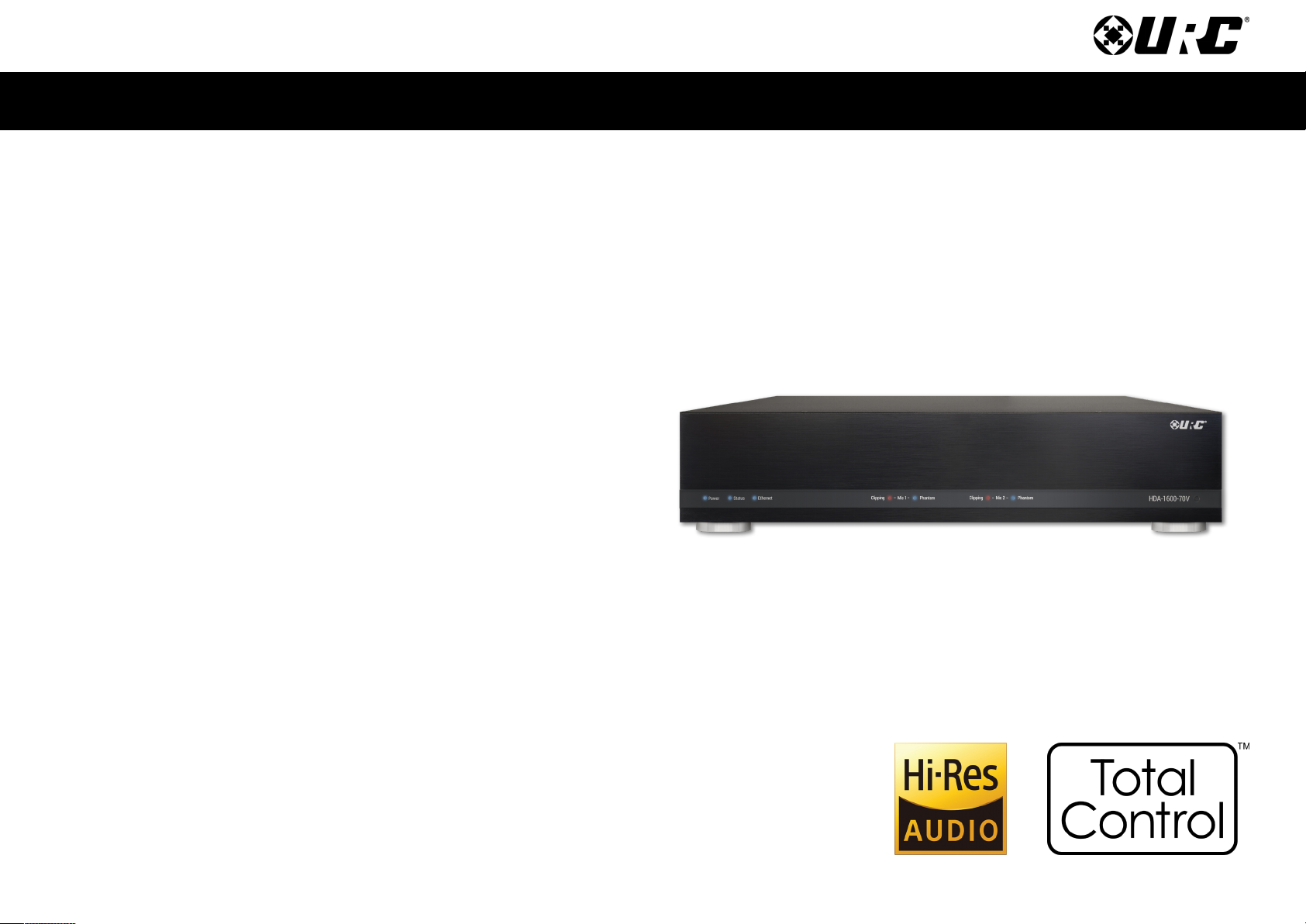
Total Control HDA-1600-70V
Owner’s Manual
Overview....................................................................................................................... 1
Features & Benefits..................................................................................................... 1
Parts & Pieces ............................................................................................................. 2
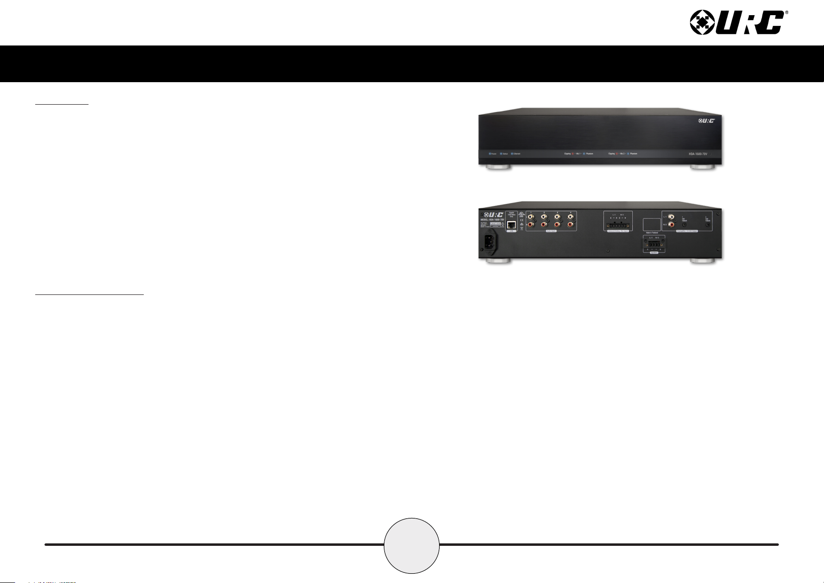
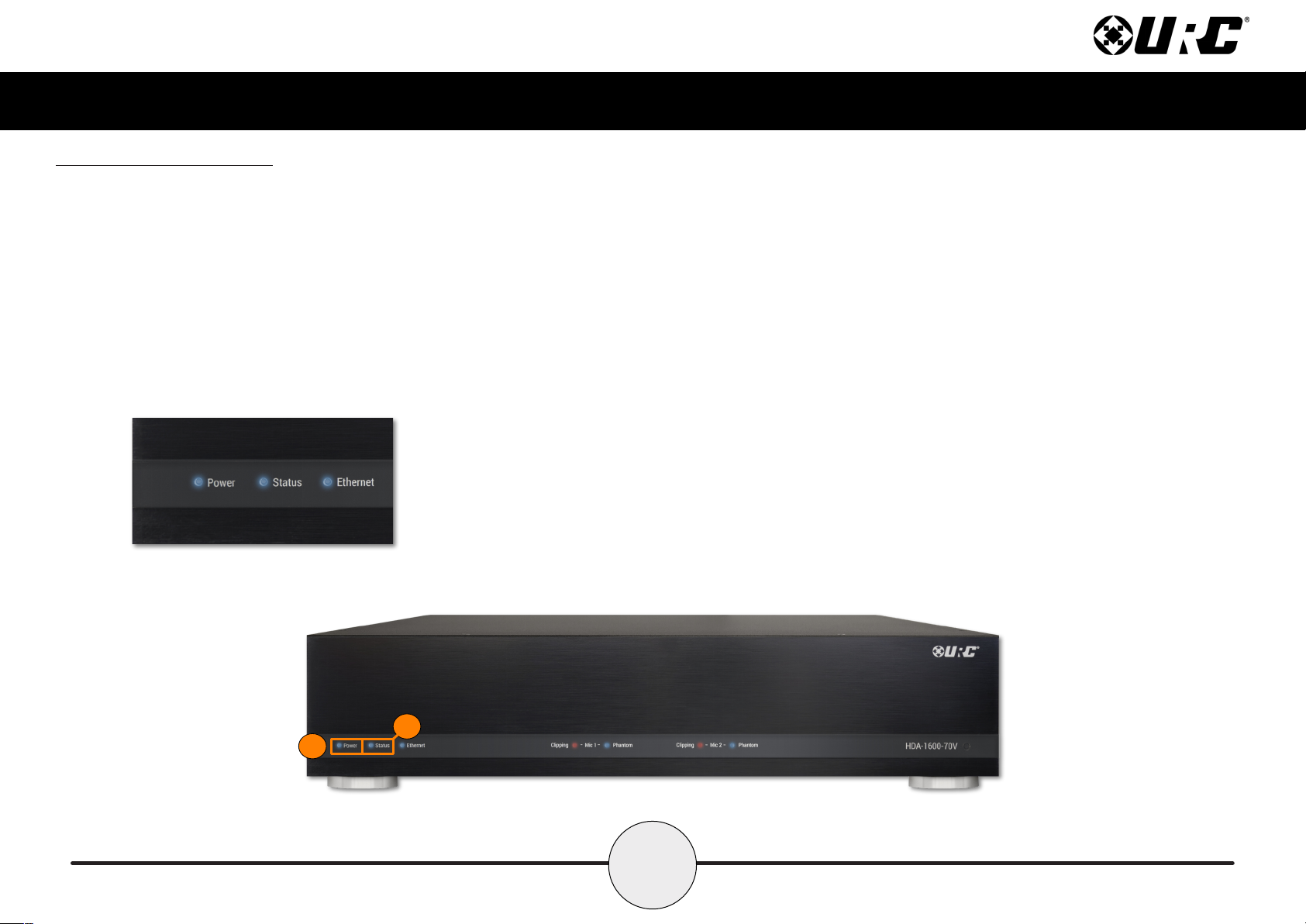
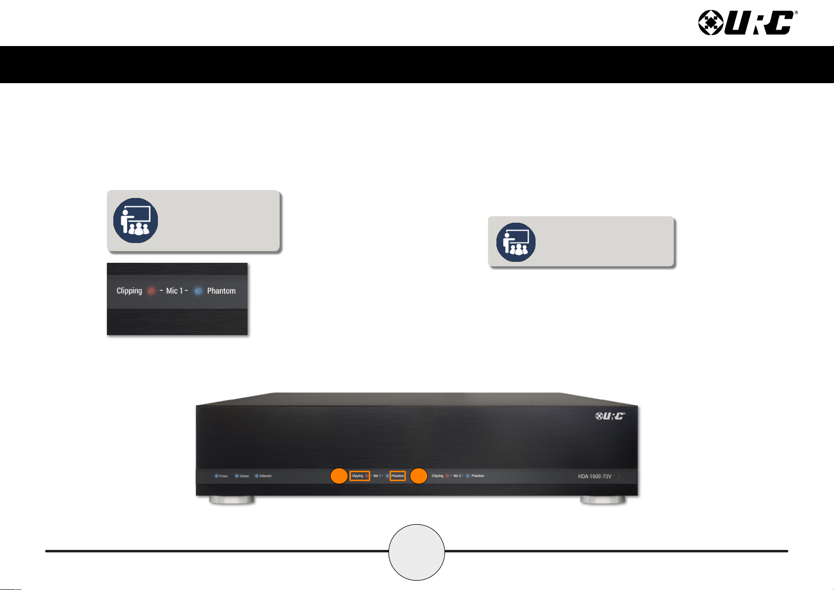
Front Panel Descriptions ........................................................................................... 3
Rear Panel Description .............................................................................................. 7
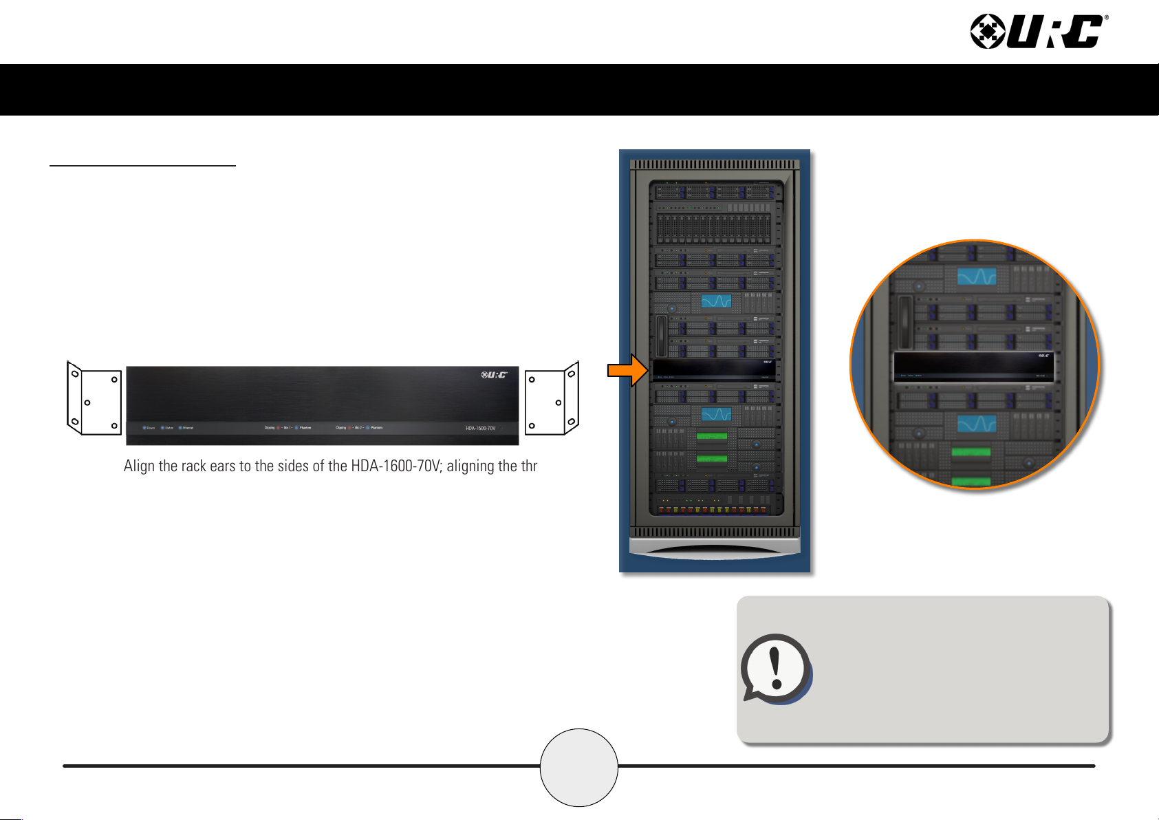
Installation Instructions............................................................................................. 8
Connecting peakers ................................................................................................. 9
Using the XLR to Phoenix Adapter ......................................................................... 10
Network etup........................................................................................................... 11
HDA-1600-70V Configurable Options ..................................................................... 12
HDA Modules ............................................................................................................. 13
pecifications ............................................................................................................ 14
AFETY PRECAUTION ............................................................................................ 16
Important afety Instructions.................................................................................. 17
Caution: ....................................................................................................................... 17
Federal Communications Commission.................................................................. 18
Interference tatement ............................................................................................ 18
Warning! ..................................................................................................................... 18
FCC Caution ................................................................................................................ 18
Limited Warranty tatement.................................................................................... 19
End User Agreement ................................................................................................. 21
Table of Contents
Congratulations!
The HDA-1600-70V Multi-Zone Amplifier is URC’s powerful and discrete amplier!
This document highlights product features, LED status conditions, basic installation, and
general speaker wiring instructions
For questions on how this device operates contact your certified URC Integrator or
URC’s Technical upport Team!
Technical Suppor t
Toll Free: 800-904-0800
Main: 914-835-4484
techsupport@urc-automation.com
H o u r s : 9 : 0 0 a m - 6 p m E S T M - F