URC HDA-4100 User manual


Total Control HDA-4100
Owner’s Manual
Overview....................................................................................................................... 1
Features & Benefits..................................................................................................... 1
Parts & Pieces ............................................................................................................. 2
Front Panel Descriptions ........................................................................................... 3
Rear Panel Description .............................................................................................. 5
Installation Instructions............................................................................................. 6
Connecting peakers ................................................................................................. 7
Network etup............................................................................................................. 8
HDA Modules ............................................................................................................... 9
pecifications ............................................................................................................ 10
AFETY PRECAUTION ............................................................................................ 12
Important afety Instructions.................................................................................. 13
Caution ........................................................................................................................ 13
Federal Communications Commission.................................................................. 14
Interference tatement ............................................................................................ 14
Warning! ..................................................................................................................... 14
FCC Caution ................................................................................................................ 14
Limited Warranty tatement.................................................................................... 15
End User Agreement ................................................................................................. 17
Table of Contents
Congratulations!
The HDA-4100 Multi-Zone Amplifier is one of URC’s powerful yet exible amplier!
This document highlights product features, L D status conditions, basic installation, and
general speaker wiring instructions.
For questions on how this device operates contact your certified URC Integrator or
URC’s Technical upport Team!
Technical Suppor t
Toll Free: 800-904-0800
Main: 914-835-4484
techsupport@urc-automation.com
H o u r s : 9 : 0 0 a m - 6 p m E S T M - F

1
Total Control HDA-4100
Owner’s Manual
Overview
URC’s HDA-4100 Multi-Zone amplier delivers incredible performance, reliability, and
powerful amplication making it the perfect audio distribution system for any home or
business. The HDA-4100 can provide audio in up to four (4) stereo zones,eight (8)
mono zones, or any combination of both.
The HDA-4100 Multi-Zone amplier is designed with ICEpower technology to provide
a robust, cool running distributed audio system.
Using URC’s HDA ampliers in conjunction with URC architectural in-ceiling
speakers delivers an incredible high-delity audio experience throughout the
home or business.
HDA products are NOT compatible with URC’s legacy Total Control ampliers (DMS).
Features & Benefits
• Flexible Multi-Zone Configuration: With support of up to four (4) powered
stereo zones, up to eight (8) mono zones, or any combination.
• HDA Audio treams: This device supports up to four (4) audio sources that are
converted into a digital “high resolution” audio stream over the network.
• ource haring: Any zone controlled via an HDA amplier or I/O device has
access to the system’s HDA Audio Streams.
• 100W of Power at 8Ω (200W per zone) driven by IC power modules to provide
a high-delity audio experience.
• Flexible Zone Linking: Link one or more zones on the y via Total Control’s
Rooms Menu or have your programmer congure a “Party Mode” button.
Room Linking is an easy way to distribute audio across the system.
• Integrated Audio ensor: ach available input on the HDA-4100 has built-in
audio sensing capabilities. These sensors can be used to trigger programmed
events or activities.
• Zone Input Ducking: The HDA-4100 has the ability to “fade in” an audio input
over the currently selected audio input.
The perfect solution to briey lower the volume on the current source to make
an audio announcement or doorbell chime.
• Rack-mountable with included rack ears.
2
Total Control HDA-4100
Owner’s Manual
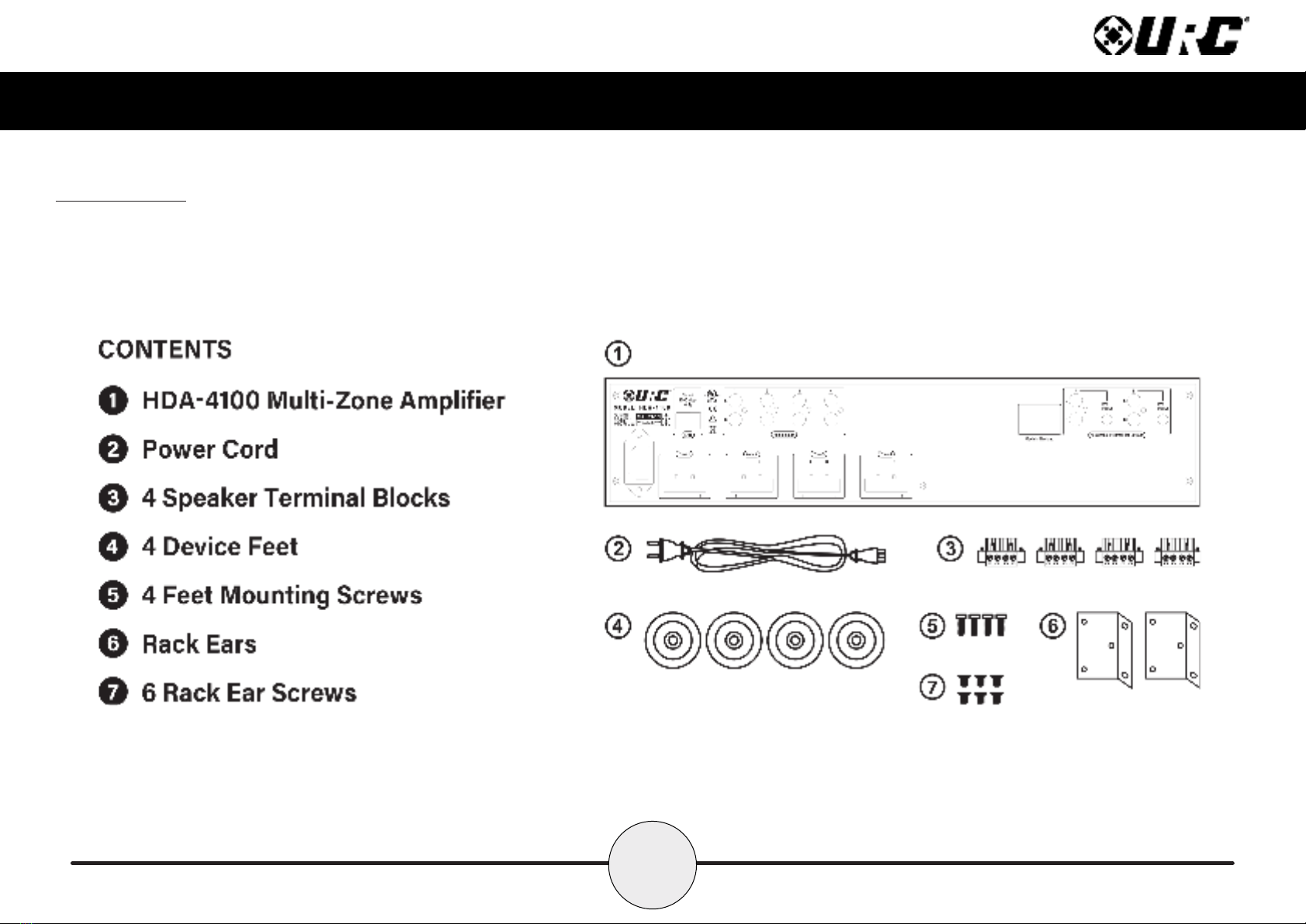
Parts & Pieces
Included with the HDA-4100 is the following:

3
Total Control HDA-4100
Owner’s Manual
Front Panel Descriptions
There are three (3) L Ds on the front panel of the HDA-4100:
1. Power LED: Indicates one (1) of the following:
• olid Blue: Power has been applied to the device and it has
successfully initialized.
• Off: Power has been removed from the device.
2. tatus LED: Indicates one (1) of the following:
• olid Blue: The device has been programmed with Total Control software
and is ready for operation.
• Blinking Blue: The device is receiving a download from the Total Control
programming software.
• Blinking Green: The device is receiving a rmware upgrade, this light
continues to blink until the update is fully applied.
• Off: The device has not been programmed with Total Control software.
1
2

4
Total Control HDA-4100
Owner’s Manual
3. Ethernet LED: Indicates one (1) of the following:
• olid Blue: The device has received an IP address from the local network.
• Blinking Blue: The device is connected to the local network; however, it
has not received an IP address.
• Off: The device is not connected to the local network.
4. Reset Button: There are two (2) ways to press this button:
• ingle Press: Tap the Reset button to power cycle the device.
• Factory Reset: Press-n-hold the Reset button for 10 seconds or more.
This option cannot be reversed, once the device has been factory defaulted
it requires re-programming.
34

5
Total Control HDA-4100
Owner’s Manual
Rear Panel Description
Below are the available connections on the rear of the HDA-4100:
1. LAN: Full duplex gigabit LAN (only), for audio streaming and zone control (Wi-Fi
NOT available, device must be hard-lined to the network.
2. Audio Inputs: The HDA-4100 Multi-Zone Amplier contains four (4) RCA
(single ended) stereo inputs.
3. Assignable Preamplifier Outputs: Two (2) assignable preamplier outputs,
each with 12V programmable triggers are capable of 150mA of current.
4. Zone peaker Outputs: Supports up to four (4) stereo (L + R) zones, eight (8)
mono zones, or any combination of stereo/mono zones (phoenix connector).
5. AC Main Power: Connect the supplied power cable to provide the HDA-4100
with power.
lotted-styled screws are
used to secure the speaker wire
to the terminal block/phoenix
style connector.
1
23
5
4

6
Total Control HDA-4100
Owner’s Manual
Installation Instructions
The HDA-4100 Multi-Zone Amplier comes with rack-mounting ears and can be installed
in a 2U rack space.
Installing the HDA-4100 in a Rack:
1. Using a cross-head screw driver, remove the HDA-4100’s feet from the
bottom of the device.
2. Attach the rack ears to the left and right sides of the amplier using the
supplied screws.
Align the rack ears to the sides of the HDA-4100 aligning the three (3)
screw inserts with the slots on the left and right sides of the devices.
Turn all three (3) cross-styled screws clockwise until the rack ears are
secured onto the device’s chassis.
3. Install into the rack (2U rack space) and connect cabling.
4. Use the supplied cross-styled screws (4) to secure the HDA-4100 (with rack
ears installed) to the equipment rack.
CAUTION!
To prevent damage, maintain adequate ventilation
space to the sides of the amplier.
Ampliers can be stacked vertically, but assure that
the device is NOT placed next to other components or
against the side of a cabinet. Doing so may block
ventilation openings.

7
Total Control HDA-4100
Owner’s Manual
Connecting peakers
The HDA-4100 Multi-Zone Amplifier can power up to four (4) stereo zones, eight (8)
mono zones or any combination of stereo/mono.
To connect speaker wire:
1. Connect the speaker wire to the positive (red) and negative (black) to the wire
terminals available on the speaker (be mindful of proper polarity).
Please refer to the manufacture’s owner’s manual for specic instructions on
wiring the speaker.
2. Loosen the integrated slotted-style screws (turn counter-clockwise) and remove
the phoenix connector from the terminal block on the HDA-4100.
3. Secure the speaker wire into the phoenix connector (using the integrated
slotted-styled screws), and reinsert it into the terminal block.
4. Using the integrated slotted-styled screws on the
left and right sides of the phoenix connector
(image at the right), secure the phoenix
connector to the terminal block.
CAUTION! Verify the polarity of the
speakers and the wires before
returning the phoenix connector into
the terminal block on the amplier.
6.5” SP-6EX
HDA-4100

8
Total Control HDA-4100
Owner’s Manual
Network etup
When using more than one (1) HDA devices, URC’s HDA- W5 Network witch is
REQUIRED on the local network.
For more information of the HDA- W5 Network witch, please refer to the
HDA-SW5 Owner’s Manual.
Although 3rd Party AVB switches may be utilized, they are not supported by
URC’s Technical Support team.
Connecting the HDA-4100 to the Network:
1. Connect an ethernet cable to an available LAN port on the head-end
network switch.
If no switch is connected to the network then connect the ethernet cable to
an available LAN port on the local router (Luxul preferred).
2. Connect the ethernet cable from the previous step to any available LAN port
on the HDA- W5.
3. Connect another ethernet cable to an available LAN port on the
HDA- W5 Network witch.
4. Connect the ethernet cable from the previous step to the ethernet port
found at the rear of the HDA-4100 (page 5).
5. Congure the HDA-4100 to a DHCP/MAC reservation within the local
router and program the device into the new or existing Total Control system.
Acertified URC integrator is REQUIRED to integrate the HDA-4100 into
a new or existing Total Control system.
1 2
HDA-4100
Local Router HDA-SW5 Network Switch
Table of contents
Other URC Amplifier manuals

URC
URC Total control DMS-100 User manual

URC
URC Total control DMS-100 User manual

URC
URC DMS-OUT User manual

URC
URC Total Control HDA-130 User manual

URC
URC Total Control DMS-1200 User manual

URC
URC Total Control DMS-1200 User manual

URC
URC Total Control HDA-1600-70V User manual

URC
URC HDA-8100 User manual

URC
URC HDA-I/O User manual

URC
URC Total control DMS-100 Reference manual


