DS1038-002A 1716 DS1038-002A
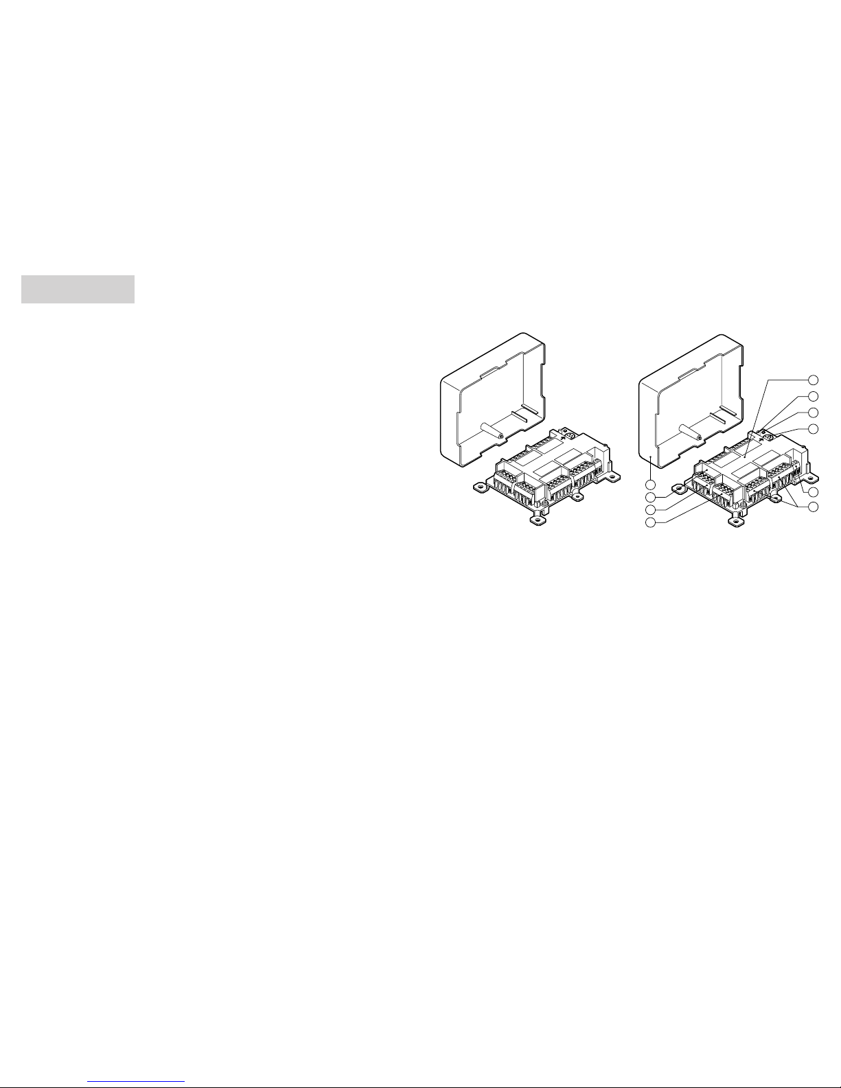
DESCRIPTION DES BORNES
Bornes de la colonne montante:
+V Positif d’alimentation (+24V)
0V Masse d’alimentation et ligne de données
D Ligne de données
FA Conducteur de phonie aller
FB Conducteur de phonie retour
Bornes des dérivations aux postes
d’appartement:
0V Masse de la ligne d’appel, services et appel à
l’étage
CA ligne d’appel et services
FA Conducteur de phonie aller
FB Conducteur de phonie retour
CP Conducteur d’appel àl’étage
CV Conducteur d’appel vidéo
Bornes pour le kit mute/voyant porte ouverte:
PA Alimentation circuit indication porte ouverte
MU Alimentation circuit mute
CARACTERISTIQUES TECHNIQUES
Consommation en termes de charge unitaires (CU):
- Branchement sans kit touche mute/led
Rèf.1138/52: 1.5 CU
- Branchement avec kit touche mute/led
Rèf.1138/52: 2.5 CU
Tension d’alimentation: 12 - 25,2 Vcc
Absorption maximum au repos: 20 mA
Température de fonctionnement: -10°C +45°C
FONCTIONNEMENT DE BASE
Ledécodeur Réf.1038/35 permet de brancher jusqu’à
un maximum de 4 usagers, chacun d’entre eux
pouvant brancher au maximum deux postes
d’appartementenparallèle (portiers ou vidéoportiers).
En phase de programmation (voir le paragraphe
Programmation), un code doit être attribuéàchaque
usager. Ces codes résident sur une mémoire de
type EEPROM qui les conserve même si
l’alimentation vient àmanquer.
Avec les postes d’appartement Réf.1138/2, il faut
également programmer les codes associés aux
deux touches supplémentaires.
Pendant le fonctionnement, le dispositif décodeur
analyse le code émis par le dispositif qui a effectué
l’appel, et, s’il correspond àl’un de ceux pour
lesquels il a étéprogrammé, il envoie le signal
d’appel opportun àl’utilisateur qui y est associé
(poste d’appartement).
La conversation est activée pour 10 minutes au
maximum (time-out), sauf si elle est interrompue par
un appel vers un autre usager. S’il y a un signal vidéo,
il persiste pendant toute la durée de la conversation.
En cas d’interruption de la conversation parce que
le délai maximum s’est écouléou suite àl’appel
d’un autre usager, le décodeur émet une tonalitéde
courtoisie afin de signaler àl’usager que la
communication a étéinterrompue.
On peut envoyer trois commandes distinctes à
partir du poste d’appartement (Réf.1138/2) et/ou du
poste d’appartement vidéo (Réf.1138/2+Réf.1732/
1+Réf.1732/92) en appuyant sur les touches
correspondantes : “Ouverture de porte”, “Appel àla
centrale de portier “et “Appel àportier spécial “. Le
décodeur émet une tonalitéde courtoisie àchaque
commande envoyée.
La commande d’ouverture de la porte est unique
même si le système est pourvu de plusieurs postes
d’appel avec leur serrure électrique respective.
Quand on actionne la touche d’ouverture de porte,
elle agit uniquement sur la serrure correspondant
au poste d’oùl’appel a étéeffectué.
PRESTATIONS SUPPLEMENTAIRES
Fonction vidéo
Le décodeur pour 4 usagers Réf.1038/35 est
prédisposépour le branchement d’un poste
d’appartement de vidéoportier, composéd’un poste
d’appartement Réf.1138 ou Réf.1138/2, associéàun
module vidéo Réf.1732/1 avec étrier Réf.1732/92.
Cette prestation permet, au moment de l’appel,
d’activer le poste d’appartement vidéo
correspondant àl’usager appeléet de le désactiver
quand la communication s’achève (par Time-out ou
du fait d’un appel àun autre usager). Si aucune
réponse ne fait suite àl’appel, le signal vidéo
persiste pendant 30 secondes au maximum.
Auto-insertion
Cette fonction permet àun poste d’appartement
vidéode visualiser l’image encadrée par les caméras
du système (en général pour surveillance/contrôle)
sans qu’il soit nécessaire d’y consacrer des
câblages.
En utilisant un poste d’appartement Réf.1138/2 sur
le poste de vidéoportier, on peut obtenir l’auto-
insertion sur une ou deux caméras. La demande
d’auto-insertion se fait en appuyant sur l’une des
deux touches du poste d’appartement et elle est
satisfaite uniquement si c’est compatible avec la
situation courante, afin de ne pas interrompre des
conversations qui pourraient être en cours. Pour
davantage d’informations, il est conseilléde
consulter le paragraphe Programmation de ce
manuel ainsi que le ‘Manuel Technique Systèmes
Intégrés’.
Appel àl’étage
Le décodeur pour 4 usagers Réf.1038/35 intégre la
fonctiond’appelàl ’étage. Pour avoir cette prestation,
il suffit de connecter une touche avec un contact
normalement ouvert aux bornes ‘CP’et ‘0V’de
l’usagerconcerné. Lorsqu’on appuiera sur la touche,
le décodeur enverra àl’usager concernéun appel
dont la durée est proportionnelle àla pression de la
touche mais de toute façon de 6 secondes au
maximum.
Gestion Kit mute/voyant porte ouverte Réf.1038/52
Le décodeur pour 4 usagers 1038/35 comporte une
plaque àborne fixe à2 voies pour l’interface avec
le ‘KIT MUTE/VOYANT PORTE OUVERTE’
Réf. 1038/52.
Pour davantage d’informations concernant cette
prestation, consulter le fascicule du Kit mute/voyant
porte ouverte.
Prestation ‘OUVERTURE AUTOMATIQUE DE
PORTE’
Cette prestation consiste àouvrir automatiquement
la porte àchaque fois qu’on appuie sur la touche
d’appelde l’usager qui a cette fonction(c’estsouvent
utile pour les cabinets professionnels pendant les
heures de bureau).
Cette prestation peut être habilitée de manière
indépendante pour chacun des usagers du système,
en utilisant des postes d’appartement Réf.1138/2
équipés du kit mute/voyant porte ouverte Réf.1038/52.
Pour davantage d’informations, consulter le
fascicule du Kit mute/voyant porte ouverte.
PROGRAMMATION
METHODES DE PROGRAMMATION DU
DECODEUR
Le dispositif de décodage peut être programméde
trois façons:
1. Au préalableenlaboratoire,enutilisantleterminal
de programmation Réf. 1038/55 ou un autre
dispositif d’appel et une alimentation. Il est
possibledeprogrammer ainsi tous les dispositifs
de décodage et puis de les installer àleurs
étages respectifs.
2. Directement sur le système (y compris quand il
estéteint)simplementenconnectantleTerminal
de programmation Réf. 1038/55 directement
sur le connecteur de programmation (7). C’est
le mode de programmation conseilléparce
qu’il permet une plus grande simplicitégrâce à
l’écran du terminal.
3. Sur le système alimentéen utilisant n’importe
quel dispositif d’appel. Pour cette opération, il
faut deux personnes, qui devront communiquer
par un émetteur-récepteur ou des
radiotéléphones. Une personne opérera sur le
dispositif d’appel alors que l’autre travaillera
aux étages, sur les dispositifs de décodage.
PARAMETRES PROGRAMMABLES
Il faut programmer pour chacun des dispositifs de
décodage:
•le code de colonne;
•les 4 codes usager;
•lescodesconcernantlestouchessupplémentaires
(uniquement en cas d’utilisation des postes
d’appartement Réf.1138/2).
Le code de colonne identifie la colonne oùle
décodeur est installéphysiquement. Le code de
colonne peut prendre des valeurs comprises entre
‘01’et ‘JJ’et il DOIT obligatoirement être identique
au code de colonne du poste d’appel secondaire
correspondant.
Dans le cas particulier de décodeurs installés dans
le tronçon intermédiaire entre les postes principaux
et les postes secondaires, il faudra définir le code
de colonne ‘X1’ou ‘X2’, selon que le décodeur est
connectéàla phonie 1 ou àla phonie 2.
En cas de systèmes sans postes secondaires,
TOUS les décodeurs devront avoir un code de
colonne défini à‘01’.
Le code usager est un code à4 caractères
alphanumériques, qui identifie chaque usager de
manière univoque. Les valeurs admises sont
comprises entre ‘0001’et ‘JJJJ’. Le code usager
peut être défini EN TOUTE LIBERTE, c’est àdire
sans aucun lien avec le code de colonne du
décodeur. Chaque code usager doit cependant
être UNIQUE au sein du système.
Lesdeux touches du poste d’appartement Réf.1138/
2 (touche inférieure T1 et touche supérieure T2)
peuvent être programmées pour réaliser les
fonctions suivantes:
•Code ‘0000’: appel àla centrale de portier;
•Code ‘0999’: fonction d’auto-insertion sur le
secondaire respectif;
•Code compris entre ‘0980’et ‘0989’ou bien entre
‘0990’et ‘0998’: fonction d’auto-insertion sur le
poste principal avec le code correspondant;
•Code compris entre ‘1000’et ‘JJJJ’: appel à
poste d’appartement spécial.