urmet domus 2 VOICE 1083/80 User manual

DS 1083-019D LBT 8530
Mod.
1083
DECODIFICA SPECIALE
SPECIAL DECODER
DÉCODAGE SPÉCIAL
DESCIFRE ESPECIAL
SPEZIALDECODER
Sch./Ref. 1083/80

2DS1083-019D
ITALIANO
La decodica speciale Sch. 1083/80 è dedicata al sistema 2Voice e permette l’attivazione di carichi elettrici
grazie a un relè con contatto 230Vca 5A tramite comandi (eventi) inviati dagli utenti attraverso i posti interni,
le postazioni di chiamata o il centralino presenti nel sistema.
Le applicazioni principali sono:
Apertura passi carrai.
Accensione luci scale.
Attivazione/disattivazione di carichi elettrici.
Le caratteristiche principali del dispositivo sono:
Modalità di funzionamento in monostabile con tempo di attivazione regolabile da 1 secondo a 16 minuti
oppure in commutazione (toggle).
Possibilità di attivazione tramite eventi di impianto (massimo 4 con jumper aree di competenza su C o
Q) programmabili dall’installatore.
Possibilità di attivazione tramite eventi utente (massimo 32 con jumper aree di competenza su S)
programmabili dall’installatore.
Possibilità di connessione di un pulsante remoto per l’attivazione.
A
B
C
HG
F
D
E
CODE S C Q M T
NA
PROG TIMER
ON
Sch.1083/80
NC C PCLINE
A - Dip-switch codice utente per identicazione della decodica nell’impianto
B - Jumper aree di competenza:
S = solo il dispositivo usato per acquisizione evento
C = tutti i dispositivi della colonna a cui appartiene quello usato per acquisizione evento
Q = qualunque dispositivo dell’impianto
C - Jumper modalità di commutazione
M = monostabile
T = toggle
D - Tasto e led di programmazione
E - Trimmer regolazione timer di attivazione in modalità monostabile (M)
F - Morsetti collegamento pulsante remoto (PC)
G - Morsetti collegamento linea (LINE)
H - Morsetti contatto relè di attivazione carichi elettrici (C-NC-NA)
INSTALLAZIONE
La decodica speciale può essere installata in un quadro elettrico su barra DIN (6 moduli DIN da 18mm)
oppure a muro tramite viti e tasselli (non forniti a corredo).
Per l’installazione, valgono le regole generali di installazione del sistema 2Voice contenute nel libretto di
sistema in dotazione con l’alimentatore Sch. 1083/20.
Occorre inoltre osservare le seguenti regole.
La decodica speciale può essere installata solamente utilizzando il distributore 4 utenti 2Voice Sch.
1083/55 collegandola a una delle sue 4 uscite.
•
•
•
•
•
•
•
•

3
DS1083-019D
Non è consentito il collegamento entra-esci.
Possono essere collegate solamente 2 decodiche speciali tra l’interfaccia per posti esterni Sch.
1083/75 e l’interfaccia di colonna Sch. 1083/50.
Se connessa in colonna, la decodica rientra nel conteggio del numero massimo di posti interni che si
possono collegare a seconda delle diverse tipologie di impianto.
Per la segnalazione di allarme panico al centralino la decodica deve essere installata in
colonna.
CONFIGURAZIONE
IMPOSTAZIONI DI FABBRICA
Tutte le decodiche escono di fabbrica congurate nel seguente modo:
CODE S C Q M T PROG TIMER
ON
jumper SCQ = posizione Q (tutti i dispositivi possono attivare la decodica)
jumper M/T = posizione M (monostabile)
dip-switch CODE = utente 127 (dip1 OFF dip2÷8 ON)
timer = 1 secondo
Con la congurazione di fabbrica tutti gli utenti dell’impianto (jumper SCQ = Q) possono attivare la decodica
in modo monostabile (jumper M/T = M) premendo il pulsante di chiamata a centralino.
Per ripristinare il default degli eventi programmati premere e mantenere premuto il pulsante di
programmazione per 5 secondi. Durante i 5 secondi il led rosso si accende e al suo spegnimento
ladecodicaimposteràleprogrammazionidifabbrica.
MODALITÀ DI COMMUTAZIONE
M T PROG TIMER
La commutazione del contatto del relè può avvenire in due modalità:
Monostabile – a seguito di un evento programmato per l’attivazione o alla pressione del pulsante remoto
connesso ai morsetti PC il contatto del relè commuta per un tempo variabile tra 1 secondo e 16 minuti
impostabile tramite il trimmer “timer”.
Toggle – a seguito di un evento programmato per l’attivazione o alla pressione del pulsante remoto
connesso ai morsetti PC il contatto del relè commuta e il trimmer è ininuente; il relè resta commutato
no ad un nuovo comando.
In caso di interruzione dell’alimentazione il contatto del relè non commuta la sua posizione.
Alripristinodell’alimentazionese è inmodalitàmonostabileil contatto tornaallaposizionedi
riposo,mentreseèinmodalitàtoggleilcontattomantienelaposizionecheavevaalmomento
dell’interruzione dell’alimentazione.
Per effettuare la prova del tempo di attivazione in monostabile è sufciente cortocircuitare temporaneamente
i morsetti PC e vericare il tempo di eccitazione del relé.
MODALITÀ DI FUNZIONAMENTO
La decodica speciale deve essere congurata e programmata opportunamente: il suo relè può essere
attivato a seguito di un evento se questo risulta tra quelli programmati e se soddisfa la congurazione
effettuata.
Gli eventi programmabili per la modalità di funzionamento “standard” che faranno scattare il relè nella
modalità monostabile o toggle impostata con il jumper M/T possono essere scelti tra i seguenti:
pressione pulsante apriporta pedonale da posto interno
•
•
•
—
—
—

4DS1083-019D
pressione pulsante apriporta carraio da posto interno
pressione pulsante chiamata a centralino da posto interno
pressione pulsante funzione speciale da posto interno
invio chiamata intercomunicante da posto interno verso decodica speciale
invio comando apriporta pedonale da centralino
invio comando apriporta carraio da centralino
invio codice speciale da postazione di chiamata o centralino
invio chiamata da postazione di chiamata ad un utente dell’impianto (funzione disponibile solo con
release FW maggiore o uguale a 4.0)
In alternativa al funzionamento sopra descritto, la decodica speciale può essere utilizzata per inviare la
segnalazione di allarme al centralino di portineria premendo il pulsante remoto (PC). In tal caso il dip-switch
1 deve essere posizionato su ON.
PROGRAMMAZIONE EVENTI IN MODALITÀ FUNZIONAMENTO
STANDARD (DIP 1 = OFF)
Possono essere programmati da 1 a 4 eventi se il jumper aree di competenza è in posizione C o Q oppure
no a 32 eventi con il jumper in posizione S che attiveranno il relè della decodica speciale conformemente
alla congurazione effettuata.
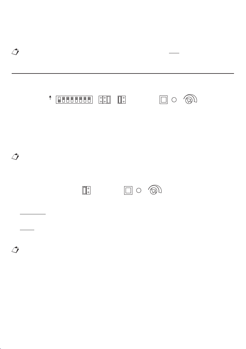
1 – Posizionare il jumper aree di competenza (SCQ) nella posizione desiderata.
2 – Posizionare i dip-switch CODE come indicato sul libretto di sistema se l’evento richiede questa
impostazione (solo per evento chiamata intercomunicante da posto interno).
3 – Premere il pulsante di programmazione e rilasciarlo quando il led si accende.
Quando si entra in programmazione gli eventi presenti in memoria saranno sovrascritti. Prima di
entrareinprogrammazionesiconsigliadiripristinareleimpostazionidifabbricaedeseguirela
programmazione degli eventi in un’unica sessione.
4 – Generare il primo evento che la decodica speciale deve acquisire (ad esempio, premere il pulsante
apriporta di un posto interno dell’impianto).
5 – Il led lampeggia 1 volta ad indicare che il primo evento è stato programmato. Il led resta acceso ad
indicare che la decodica speciale è ancora in fase di programmazione.
6 – Generare gli altri eventi che la decodica speciale deve acquisire. Per ogni evento il led lampeggerà per
un numero di volte pari al numero di eventi che sono stati programmati: 2 volte per il secondo evento,
3 per il terzo. Dopo aver programmato l’ultimo evento disponibile il led si spegnerà ad indicare l’uscita
dalla programmazione.
QuandoiljumperSCQèinposizioneSilledlampeggeràsolounavoltaindipendentementedal
numero dell’evento programmato.
7 – Uscire dalla programmazione in uno dei modi seguenti:
Premendo il tasto di programmazione
Generando lo stesso evento più volte
Attendendo lo scadere del tempo di programmazione
In ogni caso l’uscita dalla modalità di programmazione è segnalata dallo spegnimento del led.
Incasodimancataricezionedieventiperuntemposuperiorea5minuti,ladecodicaspeciale
esceautomaticamentedallostatodiprogrammazionespegnendoilled(glieventiacquisitinoa
quel momento restano memorizzati).
Si descrivono in seguito i dettagli della programmazione e del comportamento della Decodica Speciale per
ogni singolo evento programmabile.
EVENTO PRESSIONE PULSANTE APRIPORTA PEDONALE DA POSTO INTERNO
Programmare l’evento premendo il pulsante apriporta pedonale di un posto interno che dovrà attivare il relè
della decodica speciale (vedi paragrafo programmazione eventi).
Ipotizziamo che tale posto interno sia nella colonna numero “ID Colonna” e abbia codice utente “CODE”.
A programmazione effettuata, il relè viene attivato in funzione della posizione del jumper SCQ:
Posizione Q: la pressione del pulsante apriporta pedonale di qualunque utente dell’impianto attiva la
decodica.
—
—
—
—
—
—
—
—
–
–
–
•

5
DS1083-019D
Posizione C: la pressione del pulsante apriporta pedonale di ogni utente che si trova sulla colonna “ID
Colonna” attiva la decodica.
Posizione S: la pressione del pulsante apriporta pedonale di tutti i posti interni (anche quelli in parallelo)
dell’utente presente nella colonna “ID Colonna” e con codice utente “CODE” (quello usato per
l’acquisizione dell’evento) attiva la decodica.
La disposizione dei dip-switch CODE della decodica speciale è ininuente ai ni del
funzionamento con pulsante apriporta pedonale.
EVENTO PRESSIONE PULSANTE APRIPORTA CARRAIO DA POSTO INTERNO
Programmare l’evento premendo il pulsante apriporta carraio di un posto interno che dovrà attivare il relè
della decodica speciale (vedi paragrafo programmazione eventi).
Ipotizziamo che tale posto interno sia nella colonna numero “ID Colonna” e abbia codice utente “CODE”.
A programmazione effettuata, il relè viene attivato in funzione della posizione del jumper SCQ:
Posizione Q: la pressione del pulsante apriporta carraio di qualunque utente dell’impianto attiva la
decodica.
Posizione C: la pressione del pulsante apriporta carraio di ogni utente che si trova sulla colonna “ID
Colonna” attiva la decodica.
Posizione S: la pressione del pulsante apriporta carraio di tutti i posti interni (anche quelli in parallelo)
dell’utente presente nella colonna “ID Colonna” e con codice utente “CODE” (quello usato per
l’acquisizione dell’evento) attiva la decodica.
La disposizione dei dip-switch CODE della decodica speciale è ininuente ai ni del
funzionamento con pulsante apriporta carraio.
EVENTO PRESSIONE PULSANTE DI CHIAMATA A CENTRALINO DA POSTO
INTERNO
Programmare l’evento premendo il pulsante di chiamata a centralino di un posto interno che dovrà attivare
il relè della decodica speciale (vedi paragrafo programmazione eventi).
Ipotizziamo che tale posto interno sia nella colonna numero “ID Colonna” e abbia codice utente “CODE”.
A programmazione effettuata, il relè viene attivato in funzione della posizione del jumper SCQ:
Posizione Q: la pressione del pulsante di chiamata a centralino di qualunque utente dell’impianto attiva
la decodica.
Posizione C: la pressione del pulsante di chiamata a centralino di ogni utente che si trova sulla colonna
“ID Colonna” attiva la decodica.
Posizione S: la pressione del pulsante di chiamata a centralino di tutti i posti interni (anche quelli in
parallelo) dell’utente presente nella colonna “ID Colonna” e con codice utente “CODE” (quello usato per
l’acquisizione dell’evento) attiva la decodica.
La disposizione dei dip-switch CODE della decodica speciale è ininuente ai ni del
funzionamentoconpulsantedichiamataacentralino.
EVENTO PRESSIONE PULSANTI FUNZIONI SPECIALI DA POSTO INTERNO
Perconoscereinqualicondizionidiimpiantoèpossibileattivarel’eventofareriferimentoailibretti
forniti con i posti interni.
Programmare l’evento premendo un pulsante funzione speciale di un posto interno che dovrà attivare il relè
della decodica speciale (vedi paragrafo programmazione eventi).
Ipotizziamo che tale posto interno sia nella colonna numero “ID Colonna” e abbia codice utente “CODE” e
che il numero della funzione speciale associato a quel pulsante sia “SPEC”.
A programmazione effettuata, il relè viene attivato in funzione della posizione del jumper SCQ:
Posizione Q: la pressione del pulsante funzione speciale “SPEC” di qualunque utente dell’impianto
attiva la decodica.
Posizione C: la pressione del pulsante funzione speciale “SPEC” di ogni utente che si trova sulla colonna
“ID Colonna” attiva la decodica.
Posizione S: la pressione del pulsante funzione speciale “SPEC” di tutti i posti interni (anche quelli in
•
•
•
•
•
•
•
•
•
•
•

6DS1083-019D
parallelo) dell’utente presente nella colonna “ID Colonna” e con codice utente “CODE” (quello usato per
l’acquisizione dell’evento) attiva la decodica.
La disposizione dei dip-switch CODE della decodica speciale è ininuente ai ni del
funzionamento con pulsante funzioni speciali.
EVENTO CHIAMATA INTERCOMUNICANTE DA POSTO INTERNO
ATTENZIONE: Occorre avere l’accessibilità a tutti i posti interni da programmare.
Assegnare alla decodica speciale un codice utente da 0 a 127 agendo sui dip-switch CODE
considerando che nell’intero impianto non ci devono essere decodiche speciali con lo stesso codice
anche se appartenenti a colonne diverse.
Perimpostareilcodicedesideratoutilizzareidip-switchCODEda2a8(2=bitpiùsignicativo
-8=bitmenosignicativo);ildip-switch1deveessereOFF.
Mettere il jumper di selezione SCQ in posizione “S” e il jumper MT in posizione M.
Per la programmazione seguire scrupolosamente le fasi 1 e 2.
Fase 1
A seconda del modello di posto interno impiegato esistono 2 modalità diverse per entrare nello stato di
programmazione, (vericare nel libretto istruzione a corredo del prodotto qual è la tipologia impiegata):
1a) Con sgancio del microtelefono.
1 – Recarsi presso il posto interno da programmare.
2 – Tenendo premuto il pulsante apriporta, sganciare il microtelefono. Il posto interno emette un tono ad
indicare l’ingresso in programmazione.
3 – Premere il pulsante da programmare (es. ); il posto interno emette un tono di conferma.
4 – Recarsi presso la decodica speciale e premere il pulsante di programmazione (PROG) no
all’accensione del led rosso, quindi rilasciarlo. Il posto interno in programmazione emette un beep di
avvenuta programmazione.
5 – Ripremere il pulsante di programmazione della decodica speciale no allo spegnimento del led
rosso.
6 – Agganciare la cornetta dell’interno.
7 – Ripetere i punti 1, 2, 3, 4, 5, 6 per tutti i posti interni da programmare.
1b) Senza sgancio del microtelefono.
1 – Recarsi presso il posto interno da programmare.
2 – Premere e tenere premuto il tasto • per più di 5 secondi; la conferma dell’entrata in programmazione
avviene con il lampeggio lento del led giallo e l’emissione di 3 bip brevi (*)
3 – Premere il pulsante da programmare (es. ) per almeno 3 secondi no al tono di conferma.
4 – Recarsi presso la decodica speciale e premere il pulsante di programmazione (PROG) no
all’accensione del led rosso, quindi rilasciarlo. Il posto interno in programmazione emette un beep di
avvenuta programmazione.
5 – Ripremere il pulsante di programmazione della decodica speciale no allo spegnimento del led
rosso.
6 – Uscire dalla programmazione del posto interno tenendo premuto il tasto • del posto interno in
programmazione per 5 secondi, il posto interno emette un bip breve e 2 lunghi per identicare l’uscita
dalla programmazione.
7 – Ripetere i punti 1, 2, 3, 4, 5, 6 per tutti i posti interni da programmare.
(*) Comunquetrascorsi10minutiildispositivoescedallostatodiprogrammazionesalvandoiparametri
variati.
Fase 2
1 – Premere il tasto di programmazione della decodica speciale con conseguente accensione del LED
rosso.
2 – Sganciare il microtelefono(#) del primo posto interno precedentemente programmato.
3 – Premere brevemente il tasto (es. ) programmato nella Fase 1 e dedicato al pilotaggio della decodica,
•

7
DS1083-019D
il LED rosso della decodica speciale lampeggerà una volta dopodiché ritornerà nella condizione di
acceso sso; agganciare il microtelefono(#) dell’interno.
4 – Ripetere i punti 2 e 3 per tutti i rimanenti posti interni che devono pilotare la decodica.
5 – Dopo aver programmato l’ultimo interno, premendo sul tasto PROG della decodica si esce
denitivamente dallo stato di programmazione e il LED a bordo si spegne.
(#) Per i dispositivi Vivavoce premere il tasto fonia.
EVENTO COMANDO APRIPORTA PEDONALE DA CENTRALINO
Programmare l’evento inviando un comando di apriporta pedonale dal centralino (vedi paragrafo
programmazione eventi).
A programmazione effettuata, il relè viene attivato tutte le volte che si invia un comando di apriporta
pedonale dal centralino.
Ladisposizionedeidip-switchCODEedeijumperSCQdelladecodicaspecialeèininuenteai
nidelfunzionamentoconcomandodiapriportapedonaledalcentralino.
EVENTO COMANDO APRIPORTA CARRAIO DA CENTRALINO
Programmare l’evento inviando un comando di apriporta carraio dal centralino (vedi paragrafo
programmazione eventi).
A programmazione effettuata, il relè viene attivato tutte le volte che si invia un comando di apriporta carraio
dal centralino.
Ladisposizionedeidip-switchCODEedeijumperSCQdelladecodicaspecialeèininuenteai
nidelfunzionamentoconcomandodiapriportacarraiodalcentralino.
EVENTO COMANDO CODICI SPECIALI DA POSTAZIONE DI CHIAMATA O DA
CENTRALINO
Programmare l’evento inviando un codice speciale “SPEC” da una postazione di chiamata o dal centralino
che dovrà attivare il relè della decodica speciale (vedi paragrafo programmazione eventi). Il dispositivo
da cui inviare il codice speciale può essere una postazione di chiamata secondaria presente nella colonna
numero “ID Colonna”, una postazione di chiamata principale oppure un centralino.
A programmazione effettuata si vericheranno i seguenti eventi:
L’invio del codice speciale “SPEC” dal centralino attiva la decodica.
L’invio del codice speciale “SPEC” da una postazione di chiamata principale attiva la decodica.
L’invio del codice speciale “SPEC” da una postazione di chiamata secondaria attiva la decodica in
funzione della posizione del jumper SCQ:
Posizione Q: l’invio del codice speciale “SPEC” di qualunque postazione di chiamata secondaria
attiva la decodica.
Posizione C o S: l’invio del codice speciale “SPEC” di ogni postazione di chiamata secondaria che si
trova sulla colonna “ID Colonna” attiva la decodica.
La disposizione dei dip-switch CODE della decodica speciale è ininuente ai ni del
funzionamento con pulsante funzioni speciali.
EVENTO CHIAMATA DA POSTAZIONE DI CHIAMATA AD UN UTENTE
DELL’IMPIANTO
Programmare l’evento inviando una chiamata ad un utente reale (*) dalla postazione di chiamata che dovrà
attivare il relè della decodica speciale (vedere esempi e tabella riassuntiva).
(*) coniltermine“utentereale”vieneidenticatounpostointernoregolarmentecablatoefunzionante.
La postazione di chiamata può essere una postazione di chiamata secondaria presente nella
colonnanumero“IDColonna”oppureunapostazionedichiamataprincipale.
L’utentechiamatodeveavereilpostointernofunzionante.
•
•
•
–
–

8DS1083-019D
Per questo evento, a programmazione effettuata, la posizione del jumper SCQ determinerà il comportamento
descritto di seguito.
Posizione Q: l’invio della chiamata da una particolare postazione di chiamata principale verso un
qualsiasi utente reale dell’impianto attiva la decodica.
Se si vuole utilizzare la posizione Q, l’evento deve essere programmato da una postazione di chiamata
principale.
ESEMPIO
Evento programmato con chiamata dal PE principale 1 verso l’utente 01 053.
Ogni chiamata da postazione di chiamata principale 1 verso qualsiasi utente reale attiverà la
decodica.
Posizione C: l’invio della chiamata da qualsiasi postazione di chiamata secondaria presente nella
colonna numero “ID Colonna” verso un qualsiasi utente della colonna numero “ID Colonna” attiva la
decodica.
ESEMPIO
Evento programmato con chiamata dalla postazione di chiamata secondaria 0 in colonna 5 verso
l’utente 024.
Ogni chiamata da postazione di chiamata secondaria 0 oppure 1 della colonna 5 verso qualsiasi utente
reale della colonna 5 attiva la decodica.
Posizione S: l’invio della chiamata da qualsiasi postazione di chiamata (principale o secondaria) verso
un particolare utente reale attiva la decodica.
ESEMPIO
Evento programmato con chiamata da postazione di chiamata principale 3 verso l’utente 07 036.
Ogni chiamata da postazione di chiamata principale oppure secondaria della colonna 7 verso l’utente
reale 07 036 attiva la decodica.
Tabella riassuntiva
Tipologia di evento
memorizzato
Posizione del jumper aree di competenza
Q C S
Chiamata da PEP
(ben denito)
verso
PI qualsiasi
Relè commuta per attivare la
decodica
Relè commuta per attivare
la decodica solo se PI
chiamato è lo stesso verso
cui è stato memorizzato
l’evento
Chiamata da PES
(appartenente alla colonna
C) verso PI (appartenente
alla colonna C) qualsiasi
Relè commuta per attivare la
decodica
Relè commuta per attivare
la decodica solo se PI
chiamato è lo stesso verso
cui è stato memorizzato
l’evento
Chiamata da PEP verso
qualsiasi PI
(ben denito)
Relè commuta per attivare
la decodica solo se PEP
è lo stesso da cui è stato
memorizzato l’evento
Relè commuta per attivare la
decodica
Chiamata da PES
(appartenente alla colonna
C) verso PI
(ben denito)
Relè commuta per attivare
la decodica solo se PI
chiamato appartiene alla
colonna C
Relè commuta per attivare la
decodica
Legenda
Q: qualsiasi dispositivo dell’impianto PEP: posto esterno principale
C: tutti I dispositivi della colonna a cui appartiene PES: posto esterno secondario
S: solo il dispositivo usato per acquisizione evento PI: posto interno
•
•
•

9
DS1083-019D
MODALITÀ DI FUNZIONAMENTO PER SEGNALAZIONE AL CENTRALINO DI
ALLARME PANICO (DIP 1 = ON)
Questafunzionepuòessereutilizzatasoloinimpianticondecodicaspecialeinstallataincolonna
econcentralinodiportineriaconsoftwareversione3.1osuperiore.
In questa modalità di funzionamento la decodica speciale deve essere programmata nel seguente modo:
1 - Spostare il dip-switch 1 in posizione ON
2 - Assegnare alla decodica speciale un codice utente da 0 a 127 agendo sui dip-switch CODE
Perimpostareilcodicedesideratoutilizzareidip-switchda2a8(2=bitpiùsignicativo-8=bit
menosignicativo).
Ilcodiceutentepuòesserelostessogiàimpiegatoneipostiinternidellostessoappartamento.
A programmazione effettuata, premendo il pulsante remoto (PC) viene inviato al centralino un allarme panico
con l’indicazione della colonna in cui è installata la decodica e il codice utente che è stato programmato
(CODE).
Contemporaneamente il relé viene attivato in funzione delle impostazioni effettuate con le modalità di
commutazione.
CARATTERISTICHE TECNICHE
Tensione di alimentazione: ...........................................................................................................36 ÷ 48 Vcc
Assorbimento a riposo: ............................................................................................................... 3,0 mA max
Assorbimento max: ...................................................................................................................... 30 mA max
Temperatura di funzionamento: .......................................................................................... - 10 °C ÷ + 50 °C
Conformità normativa: ..................................................................................... EN 61000-6-3, EN 61000-6-1
Commutazione contatto C-NC-NA: .............................................................................................. 30 Vcc 5 A
250 Vca 5 A

10 DS1083-019D
ENGLISH
The special decoder Ref. 1083/80 is dedicated to 2Voice system and allows to activate electric loads by
means of a 230Vac 5A contact relay with commands (events) sent by users with apartment stations, call
stations or switchboard.
The main uses are:
Driveway passages opening.
Stairs lights lighting.
Electric loads activation/deactivation.
Device main features are:
Monostable operating mode with activation time adjustable from 1 second to 16 minutes, or toggle
mode.
Activation with system events (4 maximum, with competence areas jumper to C or Q) programmable
by the installer.
Possibility of activation with user events (32 max. with competence areas jumper to S), programmable
by the installer.
A remote button can be connected for activation.
A
B
C
HG
F
D
E
CODE S C Q M T
NA
PROG TIMER
ON
Sch.1083/80
NC C PCLINE
A - User code dip-switch used to identify the decoder in the system
B - Competence area jumpers:
S = only the device used to acquire the event
C = all devices of the riser column used to acquire the event
Q = any system device
C - Switch mode jumper
M = monostable
T = toggle
D - Programming button and led
E - Trimmer used to adjust the activation timer in monostable mode (M)
F - Remote button connection terminal pins (PC)
G - Line connection terminal pins (LINE)
H - Terminal pins of relay contact used to activate electric loads (C-NC-NA)
INSTALLATION
The special decoder can be installed in a service panel on DIN rail (6 18mm DIN modules) or wall mounted
with screws and screw anchors (not provided).
For installation, follow general installation instructions of 2Voice system in the system booklet provided with
the power supply ref. 1083/20.
Please observe also the following rules:
The special decoder can be installed only using the 4-user distributor 2Voice ref. 1083/55; connect it to
one of the 4 distributor outputs.
•
•
•
•
•
•
•
•

11
DS1083-019D
In-out connection is not allowed.
Between the door units interface ref. 1083/75 and the column interface ref. 1083/50 only 2 special
decoders can be connected.
If connected to the column, the decoder must be counted within the max. number of apartment stations
that can be connected, according to the different system types.
Forpanicalarmsignaltotheswitchboard,thedecodermustbeinstalledinthecolumn.
CONFIGURATION
FACTORY SETTINGS
All decoders are congured in factory as follows:
CODE S C Q M T PROG TIMER
ON
SCQ jumper = position Q (all devices can activate the decoder)
M/T jumper = position M (monostable)
CODE dip-switch = user 127 (dip1 OFF dip2÷8 ON)
timer = 1 second
With the factory conguration, all system users (SCQ jumper = Q) can activate the decoder in monostable
mode (M/T jumper = M) by pressing the ‘call to switchboard’ button.
Torestoredefaultprogrammedevents,press and keep the programming button pressedfor
5seconds.Duringthistimetheredledturnsonandwhenitturnsoffthedecoderwillrestore
defaultcongurations.
SWITCHING MODE
M T PROG TIMER
The relay contact can be switched in two modes:
Monostable – after a programmed event for activation or after the remote button connected to PC
terminal pins is pressed, the relay contact switches for a variable time of 1 second to 16 minutes; this
time can be programmed with the trimmer “timer”.
Toggle – after an activation due to a programmed event or after the remote button connected to PC
terminal pins has been pressed, the relay contact switches and the trimmer position is irrelevant; the
relay keeps this state until a new command is received.
Incaseofpowersupplyinterruption,therelaycontactdoesn’tswitchitsposition.
Whenpowersupplyisrestored,ifthespecialdecoderisinmonostablemodethecontactgoes
backtostandbyposition,ifintogglemodethecontactkeepsthepositionassumedbeforepower
supply interruption.
To test the activation time in monostable mode, short circuit temporarily the terminal pins PC and check
the relay activation time.
OPERATING MODE
The special decoder must be properly congured and programmed: its relay can be activated by an event,
if this is included in the programmed ones and matches the conguration.
Choose among the following the events programmable for “standard” operation mode, which will activate
the relay in monostable or toggle mode set with M/T jumper:
pedestrian door lock release button pressed in apartment station
driveway door lock release button pressed in apartment station
‘call to switchboard’ button pressed in apartment station
special function button pressed in apartment station
•
•
•
—
—
—
—
—
—

12 DS1083-019D
intercom call from apartment station to special decoder
sending of pedestrian door lock release command from switchboard
sending of driveway door lock release command from switchboard
sending of special code from call station or switchboard
Call from calling station to a user in the system (function available with FW release 4.0 or higher)
Alternatively to the above described operation mode, the special decoder can be used to send the alarm
indication to the concierge switchboard by pressing the remote button (PC). In this case, the dip-switch 1
must be in ON position.
EVENTS PROGRAMMING IN STANDARD OPERATING MODE (DIP
1 = OFF)
1 to 4 events can be programmed, if the competence areas jumper is in C or Q position, or up to 32 events
if the jumper is in S position: the events will activate the special decoder relay, according to conguration.
1 – Set the competence areas jumper to the desired position.
2 – Set CODE dip-switch as indicated in the system manual, if the event needs this setting (only for intercom
call coming from a door unit).
3 – Press the programming button and release it when the led turns on.
When entering in programming mode, stored events will be overwritten. Before accessing
programming mode, it is suggested to restore factory settings and program events in a single
session.
4 – Generate the rst event that the special decoder must acquire (for example, press the door lock release
button of a system apartment station).
5 – The led blinks once to indicate that the rst event has been programmed. The led stays on to indicate
that the special decoder is still in programming phase.
6 – Generate the other events which the special decoder must acquire. For each event the led will blink for
the same number of times as the events programmed: 2 times for the second event, 3 for the third.
After the last available event has been programmed, the led will turn off to indicate exit form programming
mode.
WhenSCQjumperisinSposition,theledwillblinkonlyonce,withoutindicatingtheprogrammed
eventnumber.
7 – Exit from programming mode by following one of these two procedures:
Press the programming button
Generate the same event several times
Wait until programming time is elapsed
However, exit from programming mode is indicated by the led, which turns off.
Incaseofnoeventsreceptionforatimegreaterthan5minutes,thespecialdecoderautomatically
quitstheprogrammingmodeandturnstheledoff(theeventsalreadyacquiredstaystored).
Programming details and behaviour of the special decoder for each single programmable event are
described below.
EVENT: PEDESTRIAN DOOR LOCK RELEASE BUTTON FROM APARTMENT
STATION
Program the event by pressing the pedestrian door lock release button of an apartment station, which must
activate the special decoder relay (see paragraph about events programming).
Assume that this apartment station is in the column number “Column ID” and has user code “CODE”.
When the programming procedure has been performed, the relay is activated according to the position of
the jumper SCQ:
Position Q: the pedestrian door lock release button of any system user activates the decoder.
Position C: the pedestrian door lock release button of any user of the column “Column ID” activates
the decoder.
Position S: the pedestrian door lock release button of all apartment stations (also those in parallel) of
—
—
—
—
—
–
–
–
•
•
•

13
DS1083-019D
the user in the column “Column ID” and user code “CODE” (the one used to acquire the event) activates
the decoder.
Thepositionofspecialdecoderdip-switchesCODEisirrelevantfortheoperationwithpedestrian
doorlockreleasebutton.
EVENT: DRIVEWAY DOOR LOCK RELEASE BUTTON FROM APARTMENT
STATION
Program the event by pressing the driveway door lock release button of an apartment station, which must
activate the special decoder relay (see paragraph about events programming).
Assume that this apartment station is in the column number “Column ID” and has user code “CODE”.
When the programming procedure has been performed, the relay is activated according to the position of
the jumper SCQ:
Position Q: the driveway door lock release button of any system user activates the decoder.
Position C: the driveway door lock release button of any system user in the column “Column ID”
activates the decoder.
Position S: the driveway door lock release button of all apartment stations (also those in parallel) of the
user in the column “Column ID” and user code “CODE” (the one used to acquire the event) activates
the decoder.
Thepositionofspecialdecoderdip-switchesCODEisirrelevantfortheoperationwithdriveway
doorlockreleasebutton.
EVENT: ‘CALL TO SWITCHBOARD’ BUTTON FROM APARTMENT STATION
Program the event by pressing the ‘call to switchboard’ button of an apartment station, which must activate
the special decoder relay (see paragraph about events programming).
Assume that this apartment station is in the column number “Column ID” and has user code “CODE”.
When the programming procedure has been performed, the relay is activated according to the position of
the jumper SCQ:
Position Q: the ‘call to switchboard’ button of any system user activates the decoder.
Position C: the ‘call to switchboard’ button of any system user in the column “Column ID” activates the
decoder.
Position S: the ‘call to switchboard’ button of all apartment stations (also those in parallel) of the user
in the column “Column ID” and user code “CODE” (the one used to acquire the event) activates the
decoder.
Thepositionofspecialdecoderdip-switchesCODEisirrelevantfortheoperationwith‘callto
switchboard’button.
EVENT: ‘SPECIAL FUNCTIONS’ BUTTON FROM APARTMENT STATION
Toknowsystemconditionsneededtoactivatetheevent,seebookletsprovidedwithapartment
stations.
Program the event by pressing a ‘special function’ button of an apartment station, which must activate the
special decoder relay (see paragraph about events programming).
Assume that this apartment station is in the column number “Column ID”, has user code “CODE” and the
number of the special function associated to that button is “SPEC”.
When the programming procedure has been performed, the relay is activated according to the position of
the jumper SCQ:
Position Q: the ‘special function’ button “SPEC” of any system user activates the decoder.
Position C: the ‘special function’ button “SPEC” of any system user in the column “Column ID” activates
the decoder.
Position S: the ‘special function’ button “SPEC” of all apartment stations (also those in parallel) of the
user in the column “Column ID” and user code “CODE” (the one used to acquire the event) activates
the decoder.
Thepositionofspecialdecoderdip-switchesCODEisirrelevantfortheoperationwith‘special
function’button.
•
•
•
•
•
•
•
•
•

14 DS1083-019D
EVENT: INTERCOM CALL FROM APARTMENT STATION
WARNING: Access to all the apartment stations to be programmed is required.
Assign to the special decoder a user code from 0 to 127 using the CODE dip-switches; in the system
special decoders must not have the same user code as other devices, even if belonging to different
columns.
UsetheCODEdipswitchesfrom2to8(2=mostsignicantbit-8=leastsignicantbit)toset
therequiredcode.Dipswitch1mustbeOFF.
SettheSCQselectionjumperinposition“S”andtheMTjumperinpositionM.
Follow steps 1 and 2 carefully to program.
Step 1
There are two different ways to enter programming state according to the type of apartment station used
(check which method is used on the instruction booklet supplied with the product):
1a) With handset off-hook.
1 – Go to the apartment station to be programmed.
2 – Hold the door opener button pressed and pick up the handset. The apartment station outputs a tone to
indicate that programming is in progress.
3 – Press the button to be programmed (e.g. ). The apartment station will output a conrmation tone.
4 – Go to the special decoder and press the programming button (PROG) until the red LED turns on,
then release the button. The apartment station in programming mode emits a beep to conrm the
programming.
5 – Press again the programming button of the special decoder until the red LED turns off.
6 – Hang up the apartment station handset.
7 – Repeat steps 1, 2, 3, 4, 5 and 6 for all apartment stations to be programmed.
1b) With handset on-hook
1 – Go to the apartment station to be programmed.
2 – Hold button • pressed for longer than 5 seconds; the yellow LED will blink slowly to indicate that
programming mode is selected and three short beeps will be heard. (*)
3 – Hold the button to be programmed (e.g. ) pressed for at least three seconds until the conrmation tone
is heard.
4 – Go to the special decoder and press the programming button (PROG) until the red LED turns on,
then release the button. The apartment station in programming mode emits a beep to conrm the
programming.
5 – Press again the programming button of the special decoder until the red led turns off.
6 – Exit programming mode of the apartment station by holding button • on the apartment station pressed
for 5 seconds. The apartment station will generate a beep sequence (one short beep and two long
beeps) to conrm exiting of programming mode.
7 – Repeat steps 1, 2, 3, 4, 5 and 6 for all apartment stations to be programmed.
(*) Thedevicewillexitprogrammingmodeandsavethechangedparametersinallcasesafter10minutes.
Step 2
1 – Press the special decoder programming button. The red LED will light up.
2 – Hang up the handset (#) of the rst apartment station previously programmed.
3 – Briey press the button (e.g. ) programmed in Step 1 and dedicated to operating the decoder, the red
LED on the special decoder will blink once after which it will light up xed again. Hang up the handset
(#) of the apartment station.
4 – Repeat items 2 and 3 for all the remaining apartment stations which must control the decoder.
5 – After having programmed the last apartment station, press the PROG button on the decoder to exit
programming state. The LED will be switched off.
(#) Presstheaudiobuttononhands-freedevices.
•

15
DS1083-019D
EVENT: PEDESTRIAN DOOR LOCK RELEASE COMMAND FROM
SWITCHBOARD
Program the event by sending a pedestrian door lock release command from the switchboard (see paragraph
about events programming).
When the programming has been performed, the relay is activated each time a pedestrian door lock release
command is sent from the switchboard.
Thepositionofdip-switchesCODEandjumpers SCQofspecialdecoderisirrelevantfor the
operationwithpedestriandoorlockreleasecommandfromswitchboard.
EVENT: DRIVEWAY DOOR LOCK RELEASE COMMAND FROM SWITCHBOARD
Program the event by sending a driveway door lock release command from the switchboard (see paragraph
about events programming).
When the programming has been performed, the relay is activated each time a driveway door lock release
command is sent from the switchboard.
Thepositionofdip-switchesCODEandjumpers SCQofspecialdecoderisirrelevantfor the
operationwithdrivewaydoorlockreleasecommandfromswitchboard.
EVENT: SPECIAL CODES COMMAND FROM CALL STATION OR
SWITCHBOARD
Program the event by sending a special code “SPEC” from a call station or from the switchboard that must
activate the special decoder relay (see paragraph about events programming). The device from which the
special code is sent can be a secondary call station in the column number “Column ID”, a main call station
or a switchboard.
When the programming has been performed, the following events will occur:
Sending of special code “SPEC” from the switchboard activates the decoder.
Sending of special code “SPEC” from a main call station activates the decoder.
Sending of special code “SPEC” from a secondary call station activates the decoder, according to the
position of jumper SCQ:
Position Q: Sending of special code “SPEC” from any secondary call stations activates the decoder.
Position C or S: Sending of special code “SPEC” from any secondary call stations in the column
“Column ID” activates the decoder.
Thepositionofspecialdecoderdip-switchesCODEisirrelevantfortheoperationwithspecial
functionsbuttons.
CALL EVENT FROM CALLING STATION TO A USER IN THE SYSTEM
Program the event by calling a real user (*) from the calling station which will activate the special decoder
relay (see examples and summary table).
(*) Thewords“realuser”meansacorrectlywiredandoperatingapartmentstation.
Acallingstationmaybeasecondarycallingstationincolumnnumber“ColumnID”oramain
calling station.
Theapartmentstationofthecalledusermustbeworking.
The position of the SCQ jumper will determine the following behaviour after programming for this event:
Position Q: call from a particular main calling station to any real user in the system will activate the
decoder.
To use position Q the event must be programmed from a main calling station.
EXAMPLE
Event programmed with call from main PE 1 to user 01 053.
All calls from main calling station 1 to any real user will activate the decoder.
•
•
•
–
–
•

16 DS1083-019D
Position C: call from any secondary calling station in column number “Column ID” to any user in column
number “Column ID” will activate the decoder.
EXAMPLE
Event programmed for secondary calling station 0 in column 5 to user 024.
All calls from secondary calling station 0 or 1 in column 5 to any real user in column 5 will activate the
decoder.
Position S: call from any calling station (main or secondary) to a particular real user in the system will
activate the decoder.
EXAMPLE
Event programmed with call from main calling station 3 to user 07 036.
All calls from main or secondary calling station in column 7 towards the real user 07 036 activates the
decoder.
Summary table
Stored event type Respective area jumper position
Q C S
Call from MDU (clearly
dened) to any AS
Relay switches to activate
the decoder
Relay switches to activate
the decoder only if the called
apartment station is the one
on which the event is stored
Call from SDU (on column
C) to any AS (belonging to
column C)
Relay switches to activate
the decoder
Relay switches to activate
the decoder only if the called
apartment station is the one
on which the event is stored
Call from MDU to any AS
(clearly dened)
Relay switches to activate
the decoder only if the main
calling station is the one on
which the event is stored
Relay switches to activate
the decoder
Call from SDU (belonging
to column C) to AS (well
dened)
Relay switches to activate
the decoder only if the called
apartment station belongs to
column C
Relay switches to activate
the decoder
Legenda
Q: any device in the system MDU: main door unit
C: all devices in the respective column SDU: secondary door unit
S: only the device used for event acquisition AS: apartment station
OPERATING MODE TO SIGNAL PANIC ALARM TO SWITCHBOARD (DIP1 = ON)
Thisfunctioncanbeusedonlyinsystemswithspecialdecoderinstalledinthecolumnanda
conciergeswitchboardequippedwithversion3.1orhighersoftware.
In this operating mode the special decoder must be programmed as follows:
1 – Move the dip-switch 1 in position ON
2 – Assign to the special decoder a user code from 0 to 127 using dip-switches CODE
Tosetthedesiredcodeusedip-switchesfrom2to8(2=mostsignicantbit–8=leastsignicant
bit).
Theusercodecanbethesameusedinapartmentstationsofthesameapartment.
When the programming has been performed, by pressing the remote button (PC) a panic alarm is sent to
the switchboard, with indication of the column where the decoder is installed and the programmed user
code (CODE).
At the same time the relay is activated, according to the congurations of the toggling mode.
•
•

17
DS1083-019D
TECHNICAL SPECIFICATIONS
Power supply voltage: ..................................................................................................................36 ÷ 48 Vdc
Current consumption in standby: ................................................................................................ 3,0 mA max
Max. current consumption: .......................................................................................................... 30 mA max
Operating temperature range: ............................................................................................. - 10 °C ÷ + 50 °C
Compliant with: ............................................................................................... EN 61000-6-3, EN 61000-6-1
C-NC-NA contact switching: ......................................................................................................... 30 Vdc 5 A
250 Vac 5 A

18 DS1083-019D
FRANÇAIS
Le décodage spécial Réf. 1083/80 est consacré au système 2Voice et permet l’activation de dispositifs
électriques grâce à un relais avec contact 230Vca 5A avec commandes (événements) envoyées par les
utilisateurs avec les postes internes, les postes d’appel ou la centrale présents dans le système.
Les utilisations principales sont:
Ouvertures des portes cochères.
Allumage des lumières des escaliers.
Activation/désactivation de dispositifs électriques.
Les caractéristiques principales du dispositif sont:
Mode de fonctionnement monostable avec temps d’activation réglable d’1 seconde jusqu’à 16 minutes
ou en commutation (toggle).
Possibilité d’activation par des événements du système (4 au maximum avec 4 pontets aires de
compétence sur C ou Q) qui peuvent être programmés par l’installateur.
Possibilité d’activation avec des événements utilisateurs (32 au maximum avec pontets aires de
compétence sur S) qui peuvent être programmés par l’installateur.
Possibilité de connexion d’une touche à distance pour l’activation.
A
B
C
HG
F
D
E
CODE S C Q M T
NA
PROG TIMER
ON
Sch.1083/80
NC C PCLINE
A – Dip-switch du code utilisateur pour l’identication du décodage dans le système
B – Pontet des zones de compétence:
S = seulement le dispositif utilisé pour l’acquisition de l’événement
C = tous les dispositifs de la colonne utilisée pour l’acquisition de l’événement
Q = n’importe quel dispositif du système
C – Pontet mode de commutation
M = monostable
T = toggle
D – Touche et led de programmation
E – Trimmer utilisé pour le réglage du timer d’activation en mode monostable (M)
F – Bornes de connexion de la touche à distance (PC)
G – Bornes de connexion de la ligne (LINE)
H – Bornes du contact du relais utilisé pour activer les dispositifs électriques (C-NC-NA)
INSTALLATION
Le décodage spécial peut être installé dans un panneau électrique sur barre DIN (6 modules DIN de 18mm)
ou en apparent sur le mur avec vis et chevilles (non livrées).
Pour l’installation, suivre les règles générales d’installation du système 2Voice dans le manuel de système
livré avec l’alimentation Réf. 1083/20.
Il faut observer aussi les règles suivantes.
Le décodage spécial peut être installé seulement en utilisant le distributeur 4 utilisateurs 2Voice Réf.
1083/55, en le raccordant à une de ses 4 sorties.
•
•
•
•
•
•
•
•

19
DS1083-019D
La connexion entrée/sortie n’est pas permise.
Seulement 2 décodages spéciaux peuvent être raccordés entre l’interface pour poste externes Réf.
1083/75 et l’interface de colonne Réf. 1083/50.
Si raccordé à la colonne, le décodage doit être compris dans le nombre total maximum de postes
internes qui peuvent être raccordés selon les différentes typologies de système.
Pourlasignalisationd’alarmepaniqueàlacentrale,ledécodagedoitêtreinstallédanslacolonne.
CONFIGURATION
CONFIGURATIONS IMPLICITES
Tous les décodages sont congurés en usine comme suit:
CODE S C Q M T PROG TIMER
ON
pontet SCQ = position Q (tous les dispositifs peuvent activer le décodage)
pontet M/T = position M (monostable)
dip-switch CODE = utilisateur 127 (dip1 OFF dip2÷8 ON)
timer = 1 seconde
Avec la conguration d’usine tous les utilisateurs du système (pontet SCQ = Q) peuvent activer le décodage
en mode monostable (pontet M/T = M) en appuyant sur la touche d’appel à la centrale.
Pour rétablir les événements programmés implicites, appuyer et rester appuyé sur la touche
de programmation pendant 5 secondes. Pendant ce temps, la led rouge s’allume et quand elle
s’éteintledécodagerestaureralescongurationsd’usine.
MODALITÉ DE COMMUTATION
M T PROG TIMER
Le contact du relais peut être commuté en deux modes:
Monostable – à la suite d’un événement programmé pour l’activation ou à la suite de la pression de la
touche à distance raccordée aux bornes PC, le contact du relais commute pendant un temps compris
entre 1 seconde et 16 minutes; ce temps peut être programmé avec le trimmer « timer ».
Toggle – à la suite d’un événement programmé pour l’activation ou à la suite de la pression de la
touche à distance raccordée aux bornes PC, le contact du relais commute et la position du trimmer est
insigniante; le relais reste commuté jusqu’à une nouvelle commande.
Encasd’interruptiondel’alimentation,lecontactdurelaisnecommutepassaposition.
À la restauration de l’alimentation, si en mode monostable, le contact retourne à la position
de repos, si en mode toggle le contact garde la position qu’il avait avant l’interruption de
l’alimentation.
Pour effectuer l’épreuve du temps d’activation en mode monostable il suft de court-circuiter temporairement
les bornes PC et de vérier le temps d’activation du relais.
MODE DE FONCTIONNEMENT
Le décodage spécial doit être conguré et programmé opportunément: son relais peut être activé à la
suite d’un événement, si celui-ci fait partie de ceux qui ont été programmés et s’il satisfait la conguration
effectuée.
Les événements qui peuvent être programmés pour le mode de fonctionnement «standard» et qui feront
activer le relais en mode monostable ou toggle conguré avec le pontet M/T peuvent être choisis parmi les
suivants:
pression de la touche ouvre-porte piétonne depuis un poste interne
pression de la touche ouvre-porte cochère depuis un poste interne
•
•
•
—
—
—
—

20 DS1083-019D
pression de la touche d’appel à la centrale depuis un poste interne
pression de la touche fonction spéciale depuis un poste interne
envoi appel intercom depuis un poste interne vers le décodage spécial
envoi commande ouvre-porte piétonne depuis la centrale
envoi commande ouvre-porte cochère depuis la centrale
envoi code spécial depuis un poste d’appel ou la centrale
envoi d’un appel depuis un poste d’appel vers un utilisateur du système (fonction disponible uniquement
avec une version FW égale ou supérieure à 4.0)
En alternative au fonctionnement décrit ci-dessus, le décodage spécial peut être utilisé pour envoyer la
signalisation d’alarme à la centrale de conciergerie en appuyant sur la touche à distance (PC). En ce cas-là,
le dip-switch 1 doit être positionné sur ON.
PROGRAMMATION DES ÉVÉNEMENTS EN MODE DE
FONCTIONNEMENT STANDARD (DIP 1 = OFF)
1 jusqu’à 4 événements peuvent être programmés si le pontet aires de compétence est en position C ou
Q, ou bien jusqu’à 32 événements avec le pontet en position S. Les événements activeront le relais du
décodage spécial, selon la conguration effectuée.
1 – Positionner le pontet aires de compétence ( SCQ ) dans la position désirée.
2 – Positionner les dip-switch CODE comme indiqué dans le livret de système, si l’événement demande
cette conguration ( seulement pour l’événement appel intercom depuis un poste interne ).
3 – Appuyer sur la touche de programmation et la relâcher quand la led s’allume.
Quandonentreenmodeprogrammation,lesévénementsconservésenmémoireserontécrasés.
Avantd’entrerenmodeprogrammation,ilestconseilléderestaurerlescongurationsd’usineet
deprogrammerlesévénementsenuneseulesession.
4 – Produire le premier événement que le décodage spécial doit acquérir (par exemple, appuyer sur la
touche ouvre-porte d’un poste interne du système).
5 – La led clignote une fois pour indiquer que le premier événement a été programmé. La led reste allumée
pour indiquer que le décodage spécial est encore en phase de programmation.
6 – Produire les autres événements que le décodage spécial doit acquérir. Pour chaque événement la led
clignotera pour un nombre de fois qui est le même des événements qui ont été programmés: 2 fois pour
le deuxième événement, 3 pour le troisième. Quand le dernier événement disponible a été programmé,
la led s’éteint pour indiquer la sortie du mode programmation.
Quand le pontet SCQ est en position S, la led clignote une seule fois, indépendamment du
numérodel’événementprogrammé.
7 – Sortir de la programmation selon un des modes suivants:
Appuyer sur la touche de programmation
Engendrer plusieurs fois le même événement
Attendre jusqu’à ce que le temps de programmation ne soit terminé
En tout cas, la sortie du mode programmation sera indiquée par la led, qui s’éteindra.
Siaucunévénementn’estreçupendantuntempssupérieurà5minutes,ledécodagespécial
sortautomatiquementdel’étatdeprogrammationenéteignantlaled(lesévénementsacquis
jusqu’àcemoment-làrestentmémorisés).
Les détails de la programmation et du comportement du décodage spécial pour chaque événement
programmable sont décrits ci-dessous.
ÉVÉNEMENT: PRESSION TOUCHE OUVRE-PORTE PIÉTONNE DEPUIS POSTE
INTERNE
Programmer l’événement en appuyant sur la touche ouvre-porte piétonne d’un poste interne qui devra
activer le relais du décodage spécial (voir le paragraphe sur la programmation des événements).
Supposons que ce poste interne se trouve dans la colonne numéro « ID colonne » et ait le code utilisateur
« CODE ».
Une fois terminée la programmation, le relais est activé en fonction de la position du pontet SCQ:
Position Q: la pression de la touche ouvre-porte piétonne de n’importe quel utilisateur du système
—
—
—
—
—
—
—
–
–
–
•
Table of contents
Languages:
Other urmet domus Media Converter manuals

urmet domus
urmet domus 1093/835 User manual

urmet domus
urmet domus 1083 User manual

urmet domus
urmet domus 1083 User manual

urmet domus
urmet domus IPerVoice 1039 User manual

urmet domus
urmet domus iPer VOICE 1039 User manual

urmet domus
urmet domus IPerVoice 1039 User manual

urmet domus
urmet domus Digivoice 1038 User manual