urmet domus 1068 Manual

DS1068-025A LBT20788
Mod.
1068
Through the following QR Code, it is possible to download the eventual new version of the manual.
INSTALLATION AND CONFIGURATION MANUAL
http://qrcode.urmet.com/default.aspx?prodUrmet=141749&lingua=en
RADIO MODULE
Ref. 1068/011
RADIO INTERFACE ON BUS
Ref. 1068/017
1068/011
1068/017
http://qrcode.urmet.com/default.aspx?prodUrmet=156690&lingua=en

DS1068-025A 2 LBT20788
TABLE OF CONTENTS (Rel.SW Control panel: 1.010 of 13/07/2020)
11068/011 AND 1068/017 FOR 1068 SYSTEM SERIES.............................................................................................5
CONVENTIONS ..........................................................................................................................................................5
1.1 Maximun system size for 1068/011 radio module...........................................................................................5
1.2 Maximun system size for 1068/017 radio interface.........................................................................................5
1.3 System components........................................................................................................................................6
1.3.1 1068/011 Radio module ...........................................................................................................................................6
1.3.2 1068/017 Radio interface on Bus.............................................................................................................................6
1.3.3 1051/025 Led Keypad..............................................................................................................................................7
1.3.4 1051/035 Remote control.........................................................................................................................................7
1.3.5 1051/101 –1051/102 IR Detector standard version and with PET immunity function..............................................7
1.3.6 1051/103 Dual technology indoor IR detector ..........................................................................................................8
1.3.7 1051/105 IR detector for outside with Pet immunity function....................................................................................8
1.3.8 1051/107 IR detector for outside dual technology with Pet immunity function..........................................................8
1.3.9 1051/108 IR detector curtain effect ..........................................................................................................................9
1.3.10 1051/201 –1051/202 Magnetic contact ...................................................................................................................9
1.3.11 1051/203 Multifunction magnetic contact...............................................................................................................10
1.3.12 1051/405 External siren with flashing.....................................................................................................................10
2BASIC INFORMATION..............................................................................................................................................11
2.1 How an intrusion radio alarm system and bus is made ................................................................................11
2.1.1 Radio and Bus system ...........................................................................................................................................11
3COMMAND DEVICES...............................................................................................................................................12
3.1 1051/035 Remote control..............................................................................................................................12
3.2 1051/025 Led keypad....................................................................................................................................13
4DESIGN: CONFIGURATION OF THE ALARM SYSTEM.........................................................................................14
4.1 How to design an alarm radio –bus system.................................................................................................14
4.1.1 Positioning the system devices ..............................................................................................................................14
5INSTALLATION.........................................................................................................................................................14
5.1 Installation procedure....................................................................................................................................14
5.1.1 Assembly of the 1068/011 in the control units 1068 series ....................................................................................14
5.1.2 Installation of the 1068/017 radio interface.............................................................................................................15
5.2 Radio interface connections 1068/017..........................................................................................................16
5.2.1 Connecting the data Bus........................................................................................................................................16
6COMMISSIONING.....................................................................................................................................................17
6.1 Navigation menu with 1068/021 keypad.......................................................................................................17
6.2 Enabling/disabling the 1068/011 radio module.............................................................................................18
6.3 Enabling/disabling the 1068/017 radio interface...........................................................................................18
7MAINTENANCE.........................................................................................................................................................19
7.1 Maintenance procedure ................................................................................................................................19
7.2 Acquisition of a new radio device..................................................................................................................19
7.3 Acquisition of a new 1068/017 interface on bus ...........................................................................................19
7.3.1 Procedure for acquiring bus devices (expansions, readers and radio interfaces) ..................................................19
7.4 Replacing a radio device...............................................................................................................................20
7.5 Replacing a bus device.................................................................................................................................20
7.5.1 Replacement procedure for bus devices (expansions, readers and radio interfaces)............................................20
7.6 Deleting a radio device..................................................................................................................................21
7.7 Deleting a 1068/017 radio interface or 1068/011 radio module....................................................................21
7.8 Radio connection test....................................................................................................................................22
7.9 Configuring radio parameters........................................................................................................................23
7.9.1 Devices supervision ...............................................................................................................................................23
7.9.2 Jamming.................................................................................................................................................................23
7.9.3 Enable (Available only with 1068/011 radio module)..............................................................................................24
7.9.4 Module supervision (Available only with 1068/011 radio module) ..........................................................................24

DS1068-025A 3 LBT20788
7.10 Reset factory settings....................................................................................................................................24
7.10.1 Total reset ..............................................................................................................................................................24
8SYSTEM COMMISSIONING.....................................................................................................................................25
8.1 Radio input programmig................................................................................................................................25
8.1.1 Radio input encoding..............................................................................................................................................25
8.1.2 Radio input types....................................................................................................................................................25
8.1.3 Radio input customisation ......................................................................................................................................25
8.1.4 Isolable...................................................................................................................................................................25
8.1.5 Complementary functions (Gong, Courtesy Light, Door Opener)...........................................................................25
8.1.6 Zone assignment type (AND / OR).........................................................................................................................26
8.1.7 AND inputs.............................................................................................................................................................26
8.1.8 Programming procedure.........................................................................................................................................26
8.2 Radio output programming............................................................................................................................27
8.2.1 Radio output encoding ...........................................................................................................................................28
8.2.2 Radio output customisation....................................................................................................................................28
8.2.3 Status report...........................................................................................................................................................28
8.2.4 Programming procedure.........................................................................................................................................28
8.3 1051/035 Remote control programming .......................................................................................................29
8.3.1 Programming setting key........................................................................................................................................29
8.3.2 Programming unsetting key....................................................................................................................................29
8.3.3 Programming partialization key..............................................................................................................................30
8.3.4 Programming function key......................................................................................................................................30
8.3.5 Change Name........................................................................................................................................................30
8.4 1051/025 Keypad programming....................................................................................................................31
8.4.1 Programming setting key........................................................................................................................................31
8.4.2 Programming unsetting key....................................................................................................................................31
8.4.3 Programming partialization key..............................................................................................................................31
8.4.4 Programming function key......................................................................................................................................32
8.4.5 Change Name........................................................................................................................................................32
9SYSTEM COMMISSIONING.....................................................................................................................................33
9.1 Setting using 1051/035 remote control .........................................................................................................33
9.1.1 Total setting............................................................................................................................................................33
9.1.2 Partial setting..........................................................................................................................................................33
9.2 Unsetting using 1051/035 remote control .....................................................................................................33
9.2.1 Unsetting................................................................................................................................................................33
9.3 Direct access function keys...........................................................................................................................33
9.3.1 1051/035 remote control programming key............................................................................................................33
9.4 Setting using 1051/025 keypad.....................................................................................................................33
9.4.1 Total setting............................................................................................................................................................33
9.4.2 Partial setting..........................................................................................................................................................33
9.5 Unsetting using 1051/025 keypad.................................................................................................................34
9.5.1 Unsetting................................................................................................................................................................34
9.6 Direct access function keys...........................................................................................................................34
9.6.1 1051/025 keypad programming key.......................................................................................................................34
9.7 System status information.............................................................................................................................34
9.7.1 Viewing the system status on 1051/025 keypad.....................................................................................................34
9.8 Factory settings.............................................................................................................................................34
9.8.1 1068/011 Radio module inputs...............................................................................................................................34
9.8.2 1068/017 Radio interface inputs.............................................................................................................................35
9.8.3 Radio expansions outputs (sirens).........................................................................................................................35
10 TECHNICAL SPECIFICATIONS ...............................................................................................................................36
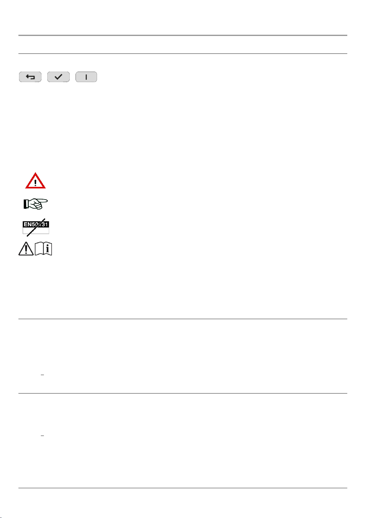
10.1 1068/011 Radio module................................................................................................................................36
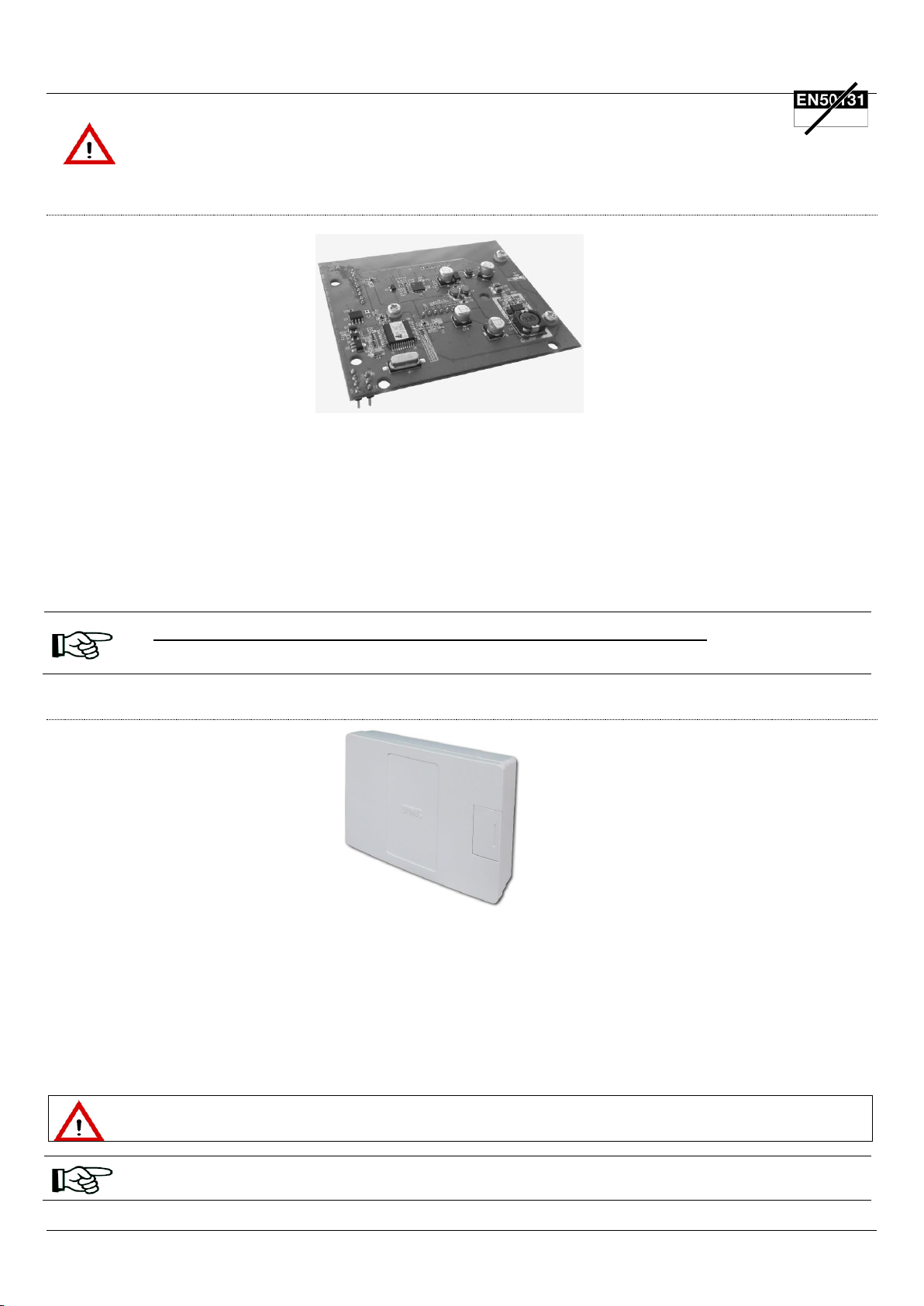
10.2 1068/017 Radio interface on bus..................................................................................................................36
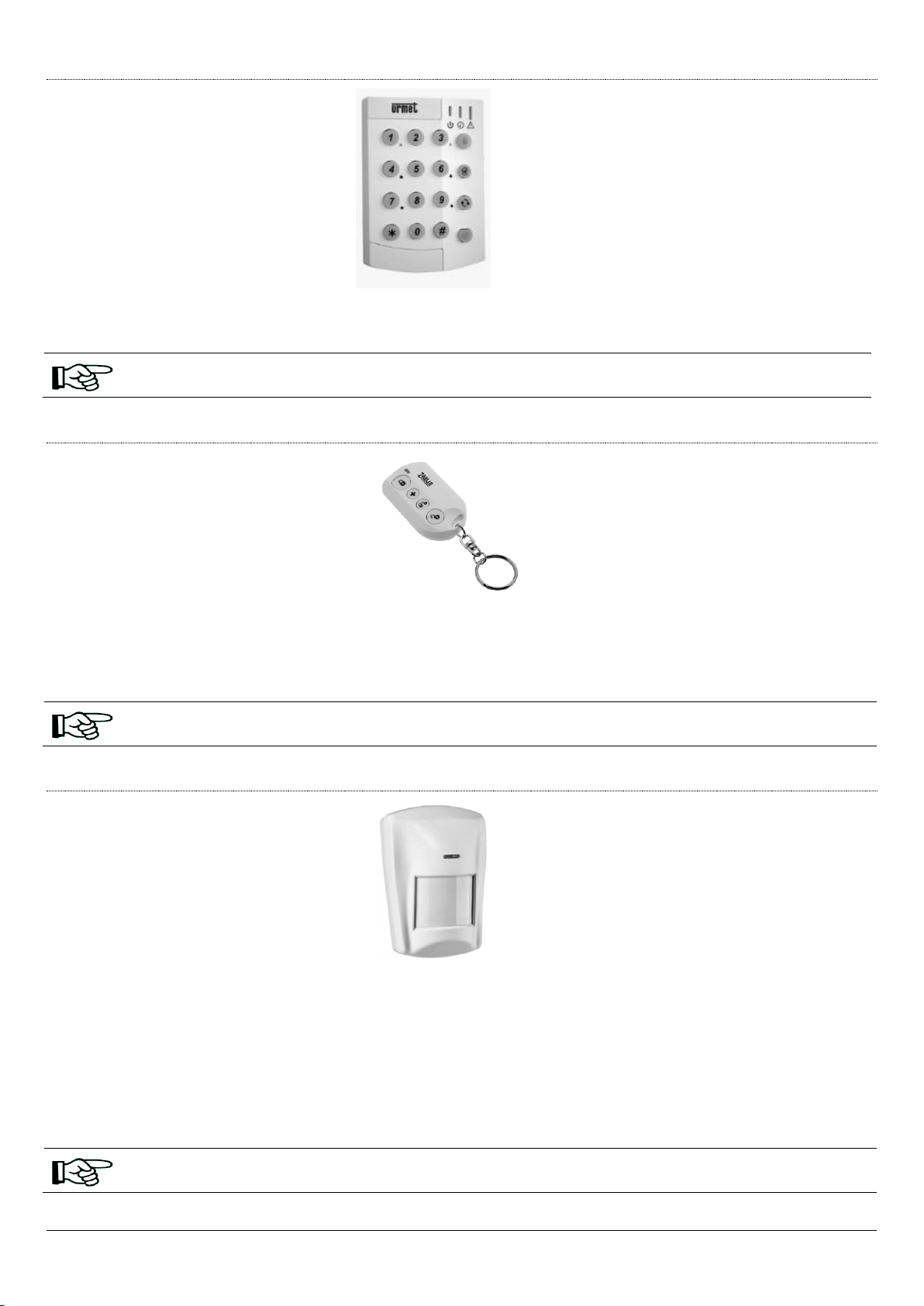
10.3 1051/025 Led keypad....................................................................................................................................36
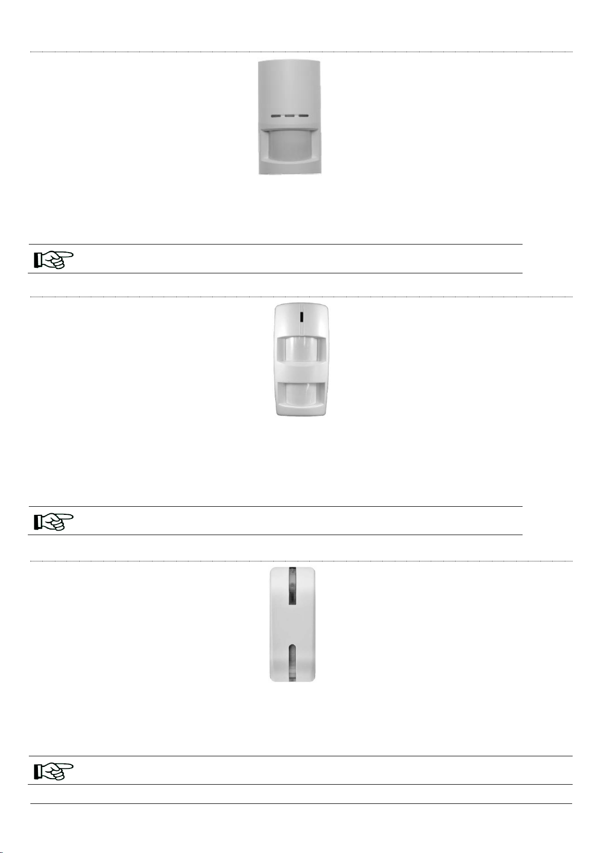
10.4 1051/035 Remote control..............................................................................................................................36

DS1068-025A 4 LBT20788
10.5 1051/101 –1051/102 IR detector standard version and with pet immunity function....................................37
10.6 1051/103 Internal IR detector dual technology.............................................................................................37
10.7 1051/105 external IR detector with pet immunity function............................................................................37
10.8 1051/107 external IR detector dual technology with pet immunity function..................................................37
10.9 1051/108 IR detector curtain effect...............................................................................................................38
10.10 1051/201 –1051-202 Magnetic contact ...................................................................................................39
10.11 1051/203 Multifunction magnetic contact .................................................................................................39
10.12 1051/405 External siren with flashing.......................................................................................................39

DS1068-025A 5 LBT20788
1 1068/011 AND 1068/017 FOR 1068 SYSTEM SERIES
CONVENTIONS
In this manual, some conventions have been used to distinguish between different types of information:
This is the equivalent key to be pressed on the keypad.
<Master code>
This indicates the code to be entered using the keypad.
<User code>
<Installer code>
<Technical Manager code>
<Master / User code>
This means that either code may be entered on the keypad indifferently.
24/7 (24 heures)
It means that the function or service described is always active.
The manual also contains symbols that provide the following information:
Warning/Important! Attention messages highlight potential system damage, data loss or non-compliance with current
regulations.
Notes: the notes contain important information, which can be useful for a better use of the system.
This symbol indicates that the function or the device invalidate the EN50131 certification.
See the installation manual of the device
⎓
Continuous supply voltage
~
Alternating supply voltage
1.1 MAXIMUN SYSTEM SIZE FOR 1068/011 RADIO MODULE
Only one 1068/011 radio module can be installed on the 1068 control panel series.
The maximum number of radiofrequency devices that can be managed by the module is:
28 IR detectors and/or magnetic contacts;
4 sirens;
8 remote controls;
4 radio keypad.
1.2 MAXIMUN SYSTEM SIZE FOR 1068/017 RADIO INTERFACE
The maximum number of radiofrequency devices that can be managed by radio interface is:
28 IR detectors and/or magnetic contacts;
4 sirens;
8 remote controls;
4 radio keypad.
If you use the control panel:
1068/005, you can only install 1 interface in place of 1068/011 radio module
1068/010, the maximum number between interface and modules is 2 (example: 1 module and 1 interface or 2 interfaces).

DS1068-025A 6 LBT20788
1.3 SYSTEM COMPONENTS
IMPORTANT!
The installation of the expansion, of the interface or radio devices results in the loss of EN50131 certification.
1.3.1 1068/011 Radio module
Optional radio module that makes it possible to integrate, radio devices as infrared detectors, magnetic contacts, sirens, remote
controls radio keypads in the wired 1068 control panels series.
The radio module is connected via a connector dedicated to the control panel and is equipped with an antenna and 868 MHz
receiver/transmitter apparatus for two-way radio communication with the combined radio devices.
The radio module can manage up to:
28 IR detectors and/or magnetic contacts;
4 sirens;
8 remote controls;
4 radio keypads.
Before using the module remember to enable it, as it is disabled by default.
For radio devices that can be combined to the 1068/011 radio module, please see the Urmet catalogue.
1.3.2 1068/017 Radio interface on Bus
Optional radio interface that makes it possible to integrate, radio devices as infrared detectors, magnetic contacts, sirens, remote
controls radio keypads in the wired 1068 control panels series.
The radio interface is connected to the control panel via bus and is equipped with an antenna and 868 MHz receiver/transmitter
apparatus for two-way radio communication with the combined radio devices.
The radio interface can manage up to:
28 IR detectors and/or magnetic contacts;
4 sirens;
8 remote controls;
4 radio keypads.
IMPORTANT! The 1068/017 radio interface is possible on the control panels and keypads that have at least SW
version 1.010-xxx or higher.
For radio devices that can be combined to the 1068/017 radio interface, please see the Urmet catalogue.

DS1068-025A 7 LBT20788
1.3.3 1051/025 Led Keypad
The Led keypad is powered by a lithium battery and communicates via radio both with the Ref. 1068/011 module and with the ref.
1068/017 interface in bidirectional mode.
It has 4 function keys, three keys for the arming and disarming of associate zones and one key for the system status.
Device usable in combination with a 1068/011 radio module and / or 1068/017 radio interface.
1.3.4 1051/035 Remote control
The remote control is powered by a lithium battery and communicates via radio both with the Ref. 1068/011 module and with the ref.
1068/017 interface in bidirectional mode.
The device has a two-tone LED to signal the command transmitted and a low battery.
The remote control has 4 programmable keys, three keys for the arming and disarming of associate zones and one key that can be
configured to enable and disable potential outputs that can be commanded or generate other types of signals.
Device usable in combination with a 1068/011 radio module and / or 1068/017 radio interface.
1.3.5 1051/101 –1051/102 IR Detector standard version and with PET immunity function
A passive infra-red detector to detect movements in the area it monitors.
It is powered by a lithium battery and communicates via radio both with the Ref. 1068/011 module and with the ref. 1068/017 interface
in bidirectional mode.
A tamper guarantees protection against opening and removal. The device has test, supervision, battery low signal, and LED to signal
radio communication.
The device can be installed in an angular position by means of the bracket provided.
The detector is designed to operate with a detection range of 12 meters, mounted at a height of 2 meters from the ground.
The 1051/102 version, allows the use of these detectors even in the presence of animals weighing less than about 27 kg, within 7
meters of flow, without generating alarms.
Device usable in combination with a 1068/011 radio module and / or 1068/017 radio interface.

DS1068-025A 8 LBT20788
1.3.6 1051/103 Dual technology indoor IR detector
The indoor detector implements infrared (PIR) and microwave (MW) motion detection technology. The combination of the two
detection methods considerably reduces the false alarm rate, employing PIR as initial detection and of microwaves for confirmation
before sending the alarm signal.
It is powered by a lithium battery and communicates via radio both with the Ref. 1068/011 module and with the ref. 1068/017 interface
in bidirectional mode.
Device usable in combination with a 1068/011 radio module and / or 1068/017 radio interface.
1.3.7 1051/105 IR detector for outside with Pet immunity function
Outdoor detector with double passive infrared (PIR) motion sensor which minimises the risk of false alarms caused by small animals,
cars or other external interferences, making it easy and practical to use.
The automatic temperature sensitivity adjustment guarantees optimal performance regardless of environmental changes or external
interferences.
Furthermore, the global detection range efficiently adapts to all installation environments.
It is powered by a lithium battery and communicates via radio both with the Ref. 1068/011 module and with the ref. 1068/017 interface
in bidirectional mode.
Device usable in combination with a 1068/011 radio module and / or 1068/017 radio interface.
1.3.8 1051/107 IR detector for outside dual technology with Pet immunity function
Detector with passive infrared (PIR) and microwave motion sensor capable of detecting movements in an assigned area and indicate
them to the control panel to activate the intrusion alarm.
The holes provided in the base of the product allow installation on a flat surface using the 90° bracket (Ref. 1033/018) or a joint (Ref.
1033/019), both of which are optional, if necessary.
It is powered by a lithium battery and communicates via radio both with the Ref. 1068/011 module and with the ref. 1068/017 interface
in bidirectional mode.
Device usable in combination with a 1068/011 radio module and / or 1068/017 radio interface.

DS1068-025A 9 LBT20788
1.3.9 1051/108 IR detector curtain effect
Detector with passive infrared (PIR) motion sensor capable of detecting movements in an assigned area and indicate them to the
control panel to activate the intrusion alarm.
The base of the product is provided with holes for installing it on a flat surface or in a corner.
The detector has a single tamper micro switch which is activated when the lid is opened. Furthermore, it can send a warning to
indicate a communication problem or flat battery conditions. The detector is designed to work within a detection field of 8 metres.
It is powered by a lithium battery and communicates via radio both with the Ref. 1068/011 module and with the ref. 1068/017 interface
in bidirectional mode.
Device usable in combination with a 1068/011 radio module and / or 1068/017 radio interface.
1.3.10 1051/201 –1051/202 Magnetic contact
Mini magnetic contact detector to monitor opening/closing of specific devices (e.g. a door or a window). The contact is fixed onto the
door or window frame, while the actuation magnet must be fixed onto the door or window itself. When the door or window is opened,
the magnet moves away from the contact making the inner magnetic switch trip and activating the sending of an alarm signal to the
control panel. The device can also send information on faults and flat battery indications.
It is powered by a lithium battery and communicates via radio both with the Ref. 1068/011 module and with the ref. 1068/017 interface
in bidirectional mode.
A tamper guarantees protection against opening and removal. The device has test, supervision, battery low signal, and LED to signal
radio communication.
Available also in brown (Ref.1051/202).
Device usable in combination with a 1068/011 radio module and / or 1068/017 radio interface.

DS1068-025A 10 LBT20788
1.3.11 1051/203 Multifunction magnetic contact
A magnetic contact detector to monitor the opening and closing status of the door or window where it is installed.
It has wired inputs which may be used to connect a NC (Normally Closed) contact of a wired device or a shutter or rolling blinds
opening detector (use of wire contacts for rolling blinds Urmet Ref. 1033/207 is recommended).
It is powered by a lithium battery and communicates via radio both with the Ref. 1068/011 module and with the ref. 1068/017 interface
in bidirectional mode.
It is programmed by a jumper. A tamper guarantees protection against opening and removal.
The device has test, supervision, battery low signal, and LED to signal radio communication.
Device usable in combination with a 1068/011 radio module and / or 1068/017 radio interface.
1.3.12 1051/405 External siren with flashing
Siren suitable for outdoor installation that signals acoustically and optically, through strobe light, an alarm condition when it receives
the related signal from the radio module 1068/011 or radio interface 1068/017.
The programming of the siren and the sounding time is done by the DIP switch.
A tamper guarantees protection against opening and removal.
It is powered by an alkaline batteries and communicates via radio both with the Ref. 1068/011 module and with the ref. 1068/017
interface in bidirectional mode.
The device has test, supervision and low battery signaling functions.
Device usable in combination with a 1068/011 radio module and / or 1068/017 radio interface.

DS1068-025A 11 LBT20788
2 BASIC INFORMATION
2.1 HOW AN INTRUSION RADIO ALARM SYSTEM AND BUS IS MADE
2.1.1 Radio and Bus system
This main distinction between installations is based on the technology used to connect the various devices to the control panel and
each other. The radio system connection is also called wireless.
Pros
Cons
Requires no wiring: all communications occur via radio and
components can be positioned where it is most convenient.
It is sensitive to radio shielding: some materials can affect the
radio waves, impeding or making communication more difficult
among the various devices.
The devices can be easily moved if the need should arise, for
example if the arrangement of furniture should change in a
room protected by a volumetric detector.
It is more sensitive to sources of electromagnetic disturbances
(ex. electric meters, electric motors, washing machines,
refrigerators, etc.), which may make communications among
the various devices difficult.
It is possible to create a system where all the components are
powered by long-life batteries, so it is not necessary to connect
the system to the electrical power supply *.
It is necessary for at least one radio channel to be free (in other
words, one channel with no other systems using it).
Quick installation: it is sufficient to install the system
components where needed, with no need to wire them.
----------------------
Installation times are considerably shorter, so as not to create
inconveniences in the home or workplace.
----------------------
*Not all manufacturers have radio alarm systems that can function entirely without being connected to the electrical utility.
Table 1 - Radio technology (tips)
Radio technology (tips):
in inhabited buildings or where it is not possible to intervene on the wall structure;
where wiring can be particularly costly and difficult;
for temporary intrusion alarm systems.
2.1.1.1 Radio apparatus
There are two types of radio apparatus used in the alarm systems: those that allow the system to connect to the external
environment, like the radio modules for the cell phone network, and those that allow wireless communications within the system,
mainly between radio devices and the control panel.
It is important to verify that the radio devices of the alarm system use the specific frequencies established by legislation and that they
are capable of using more than one radio channel.
Some may ask: can these radio devices create disturbances for other equipment present?
Are all these electromagnetic waves harmful?
The answer to the first question is very simple: the conformity with laws practically excludes this type of problem.
The same is true for the second question, but in this case it is better to analyse the topic in more detail. Above all, the radio devices
transmit with extremely low power; secondly they mainly work as receivers and transmit only when necessary and for durations of just
a few seconds. In other words: they almost never transmit and so do not emit electromagnetic waves; when they must do so it is only
for very brief moments and very low power.
2.1.1.2 The bus
A particular type of connection is the bus, which can be either wired or radio. It is essentially a channel of communication that
transfers data and information among the various devices of the system, guaranteeing their interaction.

DS1068-025A 12 LBT20788
3 COMMAND DEVICES
3.1 1051/035 REMOTE CONTROL
Figure 1 - 1051/035 Remote control
Ref.
Description
Use or indications provided
Key 1
Total arm
Arms all associated zones.
Key 2
Programmable according
to control unit
This key can only be used to arm/disarm OUTPUT devices or to generate two
different alarm types: Anti thief or Emergency.
Key 3
Partial arm
Arms all associated zones.
Key 4
Disarm
Disarms all associated zones.
5
Two-colour red/green LED
Red LED blinking one time and green LED blinking one time = the control
requested by pressing the key was received and performed by the control unit.
Red LED blinking seven times and green LED blinking one time = the
control requested by pressing the Key 2 was received and performed by the
control unit.
Red LED blinking three times = the control requested by pressing the key was
NOT received and performed by the control unit.
The indications disappear after short while.
6
Battery housing
The remote control is powered by a CR2032 3 V lithium battery.
In order to use the remote control, the 1068/011 radio module must be installed in the control unit or there must be a
connection via Bus via the 1068/017 interface.

DS1068-025A 13 LBT20788
3.2 1051/025 LED KEYPAD
Figure 2 - 1051/025 Led keypad
Ref.
Description
Use or indications provided
1
Keypad state LED
(Green/Orange)
Green LED on: the system is in Test mode.
Green LED blinking: in Test mode, this indicates flat battery.
Orange LED on for 5 seconds: the system is in normal operating mode.
The orange LED blinks for 5 seconds: it indicates flat battery in normal operating mode.
2
System state LED
(Green/Red)
Red LED on for 3 seconds: the system is in Total arming state.
Red LED blinking for 3 seconds: the system is in Partial arming state.
Green LED on for 3 seconds: the system is in Disarming state.
Green LED blinking for 4 times: error for the following reasons:
oNo reply sent to control unit within 4 seconds.
oUser error code.
oRequest to pass to Partial Armed state when the Total Armed state.
oRequest to forced setting.
3
Not used
---------------
4
Total arming key
Enter a four-digit user code and press the . key. If there are no faults and arming was
successful, the red system state LED will light up and the keypad will beep.
5
Partial arming key
Enter a four-digit user code and press the . If there are no faults and arming was
successful, the red system state LED will light up and the keypad will beep.
6
System status
verification request key
System status verification request key (see indications provided in Ref. 2).
7
Disarming key
Enter a four-digit user code and press the key, to disarm all associated zones.
8
Assembly holes cover
---------------
9
Function keys
(if enabled)
To arm, press keys 1 and 3 simultaneously
10
Keys for acquisition
Keypad
To send the keypad acquisition data to the control panel, simultaneously press the * and #
keys.
11
Assembly holes
---------------
12
Tamper
---------------
13
Battery isolator
---------------

DS1068-025A 14 LBT20788
4 DESIGN: CONFIGURATION OF THE ALARM SYSTEM
4.1 HOW TO DESIGN AN ALARM RADIO –BUS SYSTEM
4.1.1 Positioning the system devices
Unless they are specifically designed and constructed for outdoor installation, like the outdoor sirens or detectors, all the devices must
be installed indoors, protected from the elements and vandalism.
4.1.1.1 Positioning of the radio modulo 1068/011
If the radio module is used, the connection inside the 1068 control unit series is via a dedicated connector.
IMPORTANT! The installation of the radio module results in the loss of EN50131 certification.
4.1.1.2 Positioning of the radio interface 1068/017
If the radio interface is used, it must be positioned:
Inside non-metallic distribution boxes or similar containers, adequately protected by tamper-proof devices
In a dry place
In an indoor location protected by the intrusion alarm system
IMPORTANT! The installation of the radio interface results in the loss of EN50131 certification.
5 INSTALLATION
5.1 INSTALLATION PROCEDURE
5.1.1 Assembly of the 1068/011 in the control units 1068 series
The Radio module has already assembled three guide spacers A.
For assembly, proceed as follows:
1. Insert the module into the three holes B.
IMPORTANT!
The connection and disconnection of the options and accessories must always be done while the control panel is
disconnected (both mains and battery).
B
B
A
A
A
A
1068/005 Control panel
1068/010 Control panel

DS1068-025A 15 LBT20788
5.1.2 Installation of the 1068/017 radio interface
The 1068/017 radio interface is supplied with a plastic case.
The interface has terminals for connecting it to the data BUS and the LEDs that signal the functioning of the electronic board. The
tamper of the container must be connected to the SAB of the expansion.
Figure 3 - 1068/017 Radio interface
Ref.
Terminal / Detail
Description
A
+
Interface power supply via Bus
+D
Data transmission via bus
D
─
Interface power supply via Bus
Tamper
Connection for the box protection microswitch
B
Button
Buttons and LEDs for the interface acquisition.
Slow blinking for 10 sec. = possibility of deleting the device
Off after the first 10 sec. = device acquired
Slow blinking after the first 10 sec. = device not acquired
Fast blinking =device in updating
Very fast blinking =device with updating in progress
Yellow LED
C
Green LED
Operating signalling.
Slow blinking = normal operating conditions
Fast blinking = no communication with control panel from at least 1 minute
Jumper
Jumper for Tamper exclusion
(Jumper inserted = Tamper excluded)
D
Green LED
Radio interface working signaling

DS1068-025A 16 LBT20788
5.2 RADIO INTERFACE CONNECTIONS 1068/017
Belowis an explanation on how to carry out all the electrical connections and necessary signals for starting up the system.
IMPORTANT! Before running the cables, check that the sections are correct and that conform to the maximum distances.
IMPORTANT! The end of the stranded conduction must not be consolidated with a soft-solder welding in the points where
the conductor is subject to contact pressure.
Therefore it is not allowed to solder the terminals of the cables connected to the terminals of the devices.
5.2.1 Connecting the data Bus
Connect the terminals +, +D, Dand ─the cable to the 4 wires of the bus; this will enable the communications among the control
panel, readers, keypads, any expansions present. The data bust requires no terminal resistors.
The cable shieldings can be connected together in the control panel at the negative pole (─) of the power supply.
The figure below demonstrates how to connect the various devices to each other via the bus line.
Figure 4 –Connections via bus

DS1068-025A 17 LBT20788
6 COMMISSIONING
6.1 NAVIGATION MENU WITH 1068/021 KEYPAD
Programming is carried out using the keys and reading the messages and information which appear on the display.
WARNING! The keys are associated with the respective symbols located above and shown on the display.
Key
Description
It identifies a parameter and activates and deactivates a certain function associated with the relevant symbol
positioned above according to the scrolling menu.
It confirms the entered access code, accesses the displayed submenu or confirms the selection made.
It goes back to the previous page or menu level.
Symbol shown on
the display
Description
Press the key associated with the symbol to activate the zones.
Press the key associated with the symbol to deactivate the zones.
Press the key associated with the symbol for 3 seconds to activate the auxiliary keypad functions
previously programmed (for example: "Emergency" signalling).
Press the key associated with the symbol to enter the menu.
Press the key associated with the symbol to scroll up the menu.
Press the key associated with the symbol to scroll down the menu.
Press the key associated with the symbol to scroll the menu to the right.
The symbol indicates that the menu or parameter includes a submenu with multiple choice.
Press the key associated with the symbol to scroll the menu to the left.
The symbol indicates that the menu or parameter includes a submenu with multiple choice.
Press the key associated with the symbol to enable the parameter.
Press the key associated with the symbol the parameter is NOT enabled.
The symbol indicates that the parameter includes a single choice.
Press the key associated with the symbol to enable the parameter.
Press the key associated with the symbol the parameter is NOT enabled.
The symbol indicates that the parameter includes a multiple choice.

DS1068-025A 18 LBT20788
The following step-by-step programming and configuration procedures show the keys to be pressed and what appears on the display.
Text is limited to the essential minimum. The concerned function, the parameters to be configured, what the parameters are for and
the possible values are described before each procedure.
<Installer code > (0000)
<Master cod> (1111)
<Tech. Manager code> (2222)
<User code> (0010 ÷ 0160)
They indicate the code to be entered using the keypad.
The factory-set codes are listed in brackets.
<Master / User / Installer / Technical
Manager Code>
This means that either code may be entered on the keypad indifferently.
The menus are organised in a tree structure, with reciprocally nested submenus, each consisting of one or more items.
The submenu items differ according to the access code used and the system configuration.
6.2 ENABLING/DISABLING THE 1068/011 RADIO MODULE
Proceed as follows to enable a radio module:
1. Enter the INSTALLER menu by entering the access code. Press to confirm;
2. Select "System Settings" by pressing the key associated with the or symbol. Press to confirm;
3. Select "Maintenance” by pressing the key associated with the or symbol. Press to confirm;
4. Select "Radio devices" by pressing the key associated with the or symbol. Press to confirm;
5. Select "Configuration" by pressing the key associated with the or symbol. Press to confirm;
6. Select "Enable" by pressing the key associated with the or symbol. Press to confirm;
7. Press the key associated with the Enable symbol ;
Enable = parameter enabled ; Enable = parameter disabled;
8. Press to confirm.
9. Press to return to the upper level menu.
If it has acquired a number of radio devices equal to the maximum, the control panel will not allow the acquisition of others. In this specific
case, the keypad in acquisition will continue to show the data of the last device acquired and emit an error signal (a long beep).
Device acquisition is progressive. Therefore if they are to be matched to inputs and outputs in a certain order, the
precise sequence must be defined before carrying out the acquisition procedure.
6.3 ENABLING/DISABLING THE 1068/017 RADIO INTERFACE
Compared to the 1068/011 radio module, the 1068/017 radio interface cannot be enabled or disabled.
It is automatically enabled when it is acquired on the bus and disabled when deleted.

DS1068-025A 19 LBT20788
7 MAINTENANCE
7.1 MAINTENANCE PROCEDURE
See the dedicated paragraph in the Installation / Programming manual of the control units 1068 series.
7.2 ACQUISITION OF A NEW RADIO DEVICE
To acquire a new radio device, proceed as follows:
1. Enter the INSTALLER menu by entering the access code. Press to confirm;
2. Select "System Settings" by pressing the key associated with the or symbol. Press to confirm;
3. Select "Maintenance” by pressing the key associated with the or symbol. Press to confirm;
4. Select "Radio devices" by pressing the key associated with the or symbol. Press to confirm;
5. Select "Acquisition" by pressing the key associated with the or symbol. Press to confirm;
6. In presence of a Fieldbus module, you will be asked which type of expansion you want to work on (1068/011 or 1068/017), vice
versa no;
7. Select “Input devices” or “Dispositivi Output devices” by pressing the key associated with the o symbol. Press
to confirm. “ESC TO FINISH” appears on the display;
8. Press the acquisition key on the device to be acquired;
9. The address assigned to the device appears on the keypad display during acquisition;
10. Repeat step 8 on all devices to be acquired;
11. Press to return to the upper level menu.
IMPORTANT! Addresses are assigned progressively and by family; there is no need to follow a pre-established order.
If you want the device addresses to follow a given logic, you must acquire them in that order.
7.3 ACQUISITION OF A NEW 1068/017 INTERFACE ON BUS
7.3.1 Procedure for acquiring bus devices (expansions, readers and radio interfaces)
IMPORTANT! The instructions below assume that the devices have not yet been acquired.
To acquire a new bus device, from keypad (acquired or of service), follow the instructions below:
1. If the device is already connected to the BUS, go directly to step 4, otherwise turn off the system completely;
2. Connect the new device to the bus and power the system;
3. The yellow LED of the new device blink slowly for about 10 second before changing the speed of blinking;
4. Enter the INSTALLER menu by entering the access code. Press to confirm;
5. Select "System Settings" by pressing the key associated with the or symbol. Press to confirm;
6. Select "Maintenance” by pressing the key associated with the or symbol. Press to confirm;
7. Select "Acquisition" by pressing the key associated with the or symbol. Press to confirm;
8. “ESC TO FINISH…” will appear on the display; press the programming button of the device to acquire it; its yellow LED will turn off;
9. The address assigned to the device appears on the keypad display during acquisition;
10. Repeat step 8 on all devices to be acquired;
11. Press to return to the upper level menu.
For a device to be acquired it is necessary that the maximum number of devices in the family concerned has not already been
reached.
To reset the address of a device you need to:
Delete it from the appropriate keypad menu
or
Use the "reset" procedure (see paragraph “Wired device hardware reset” in the Installation / Programming manual of the
1068 / xxx control panels)
It is now possible to configure the system.
IMPORTANT! Addresses are assigned progressively and by family; there is no need to follow a pre-established order. If
you want the device addresses to follow a given logic, you must acquire them in that order.

DS1068-025A 20 LBT20788
7.4 REPLACING A RADIO DEVICE
It allows you to replace a device by assigning to the new one the same address and configuration of the previous one.
To replace a device, follow the instructions below:
1. Enter the INSTALLER menu by entering the access code. Press to confirm;
2. Select "System Settings" by pressing the key associated with the or symbol. Press to confirm;
3. Select "Maintenance” by pressing the key associated with the or symbol. Press to confirm;
4. Select "Radio devices" by pressing the key associated with the or symbol. Press to confirm;
5. Select "Substitution" by pressing the key associated with the or symbol. Press to confirm;
6. Select the device you want to replace by pressing the key associated with the or symbol. Press to confirm;
7. From the list that appears, select the device you want to replace by pressing the key associated with the or symbol.
Press to confirm;
8. The message “Are you sure?” appears on the display. Press to confirm;
9. Press the acquisition button on the new device to acquire it with the address and configuration of the previous one;
10. Press to return to the upper level menu.
IMPORTANT! In order for a radio device or reader to be replaced with another one, the two must be of the same type,
otherwise an error will be reported.
7.5 REPLACING A BUS DEVICE
7.5.1 Replacement procedure for bus devices (expansions, readers and radio interfaces)
It allows you to replace a device by assigning to the new one the same address and configuration of the previous one.
To replace a device, follow the instructions below:
1. Switch off the system completely;
2. Disconnect the device to be replaced;
3. Connect the new device to the bus;
4. Then power up the system again. The yellow LED of the new device blink slowly for about 10 second before changing the speed
of blinking;
5. Enter the INSTALLER menu by entering the access code. Press to confirm;
6. Select "System Settings" by pressing the key associated with the or symbol. Press to confirm;
7. Select "Maintenance” by pressing the key associated with the or symbol. Press to confirm;
8. Select "Substitution" by pressing the key associated with the or symbol. Press to confirm;
9. Select the device you want to replace by pressing the key associated with the or symbol. Press to confirm;
10. The message “Are you sure?” appears on the display. Press to confirm;
11. Press the programming button of the new device to acquire it with the address and configuration of the previous one; its yellow
LED turns off.
12. Press to return to the upper level menu
IMPORTANT! In order for a radio device or reader to be replaced with another one, the two must be of the same type,
otherwise an error will be reported.
Other manuals for 1068
9
This manual suits for next models
2
Table of contents