Luiton LT-298 User manual
LT-298
High Quality AM/FM CB Radio
RoHS
Compliant
0700
Owner’s Manual
Bond Telecom Co. Ltd.
Website: www.luiton.com

To User
Welcome to use LUITON LT-298 AM/FM CB radio, it is a
high quality CB radio, which suitable for Poland, Roma-
nia, Germany, UK, Italy, Russia bands.
p.1
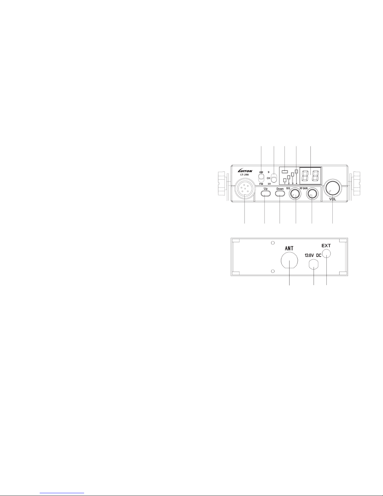
1. CONTROLS AND REAR PANEL
q w
u i o !0 !1
e r
!2 !3 !4
t y
qMICROPHONE connector
Connect the supplied electric condenser microphone to this con-
nector, and then lock it via the ring nut.
wUP KEY
Press this key and channel NO. runs up.
eDOWN KEY
Press this key channel NO. runs down.
rSQ knob
The SQUELCH control allows to silent the receiver by cutting the
background noise.
TABLE OF CONTENTS
1. CONTROLS AND REAR PANEL................................................................. 1
2. INSTALLATION.......................................................................................... 4
2.1 Installation of the Main Unit...........................................................4
2.2 Installation of the Antenna............................................................4
2.3 Checking Operation of the Radio................................................5
3. TECHNICAL INDICATORS........................................................................ 6

p.2 p.3
13.8VDC power cord input.
!4 EXT (External Speaker) Jack
This jack is for connecting an external speaker.
!5 PTT (Push-to-talk) key
Push the button to talk then release
to receiving mode.
!6 UP key of the microphone
This switch allows increasing a chan-
nel number.
!7 ASQ on and off
When you press this button, the LED
lights for TX and ASQ will light green, then ASQ pen.
!8 DN key of the microphone
This switch allows decreasing a channel number.
!9 MICROPHONE plug
6-pole microphone plug with locking ring nut, to be connected to
socket (1) located on the front side of the radio.
!5
!6 !7 !8 !9
UP ASQ DN
Turn the SQUELCH knob anticlockwise until the background noise
is cut. Rotate the SQUELCH knob clockwise (SQUELCH ON) to listen
to the weakest signals.
tRF GAIN knob
This transceiver uses a high sensitivity and selectivity receiver circuit.
The receiver gain is adjustable with the RF GAIN knob. By rotating
the knob anticlockwise, the receiver gain is reduced. It is conve-
nient to reduce the receiver gain in case of very strong signals from
local stations. This knob only functions at AM mode.
yOFF/VOL
This knob controls the radio ON and OFF as well as adjusts the vol-
ume. If no signals are being received on the operating channel,
it is suggested to turn on the SQUELCH and adjust the volume to
the desired level while listening to the background noise. When it is
turned on by operating the Volume knob,the radio will remember
the channel, frequency, AM or FM used last time.
uAM/FM mode selector
This switch allows selecting the modulation mode AM or FM.
iCH9/CH19
This function can select emergency channel CH19 and CH9
Note: In the off state,turn to CH9 can select the frequency of other
European countries, and turn to CH can conrm. Restart the radio
will prompt the current frequency table.
oTX and ASQ LED
The indicator light is bi-color,red light and green light, transmitting
shows red light, and open ASQ shows green light.
!0 RX Signal Meter
4-bar RX signal Meter to monitor the strength of the received sig-
nals.
!1 DISPLAY
The digital LED display shows the channel.
!2 ANTENNA CONNECTOR
Refer to the section INTALLTION OF THE ANTENNA.
!3 13.8 VDC POWER CORD
p.4 p.5
vehicle with proper connection to ground. Before connecting the
antenna to the radio, it is necessary to check the correct operation
of the antenna with low standing wave ratio (S.W.R.) via adequate
instruments. If not, the transmitter circuit of the radio could be dam-
aged. The antenna usually must be installed on the highest part of
the vehicle, free from obstacles and as far away as possible from any
source of electric or electromagnetic noise. The RF antenna coaxial
cable must not be damaged or pressed on its way between anten-
na and the radio. The correct operation of the antenna and the low
standing wave ratio (S.W.R.) must be checked periodically. Connect
the RF antenna coaxial cable to the antenna connector !5, located
on the rear side of the radio.
2.3 CHECKING OPERATION OF THE RADIO
Once radio has been connected to the vehicle electric system
and to the antenna, the correct operation of the system should be
checked. Please proceed as following:
1) Check that the power cable is correctly connected.
2) Check that the RF antenna coaxial cable is properly connected.
3) Connect the microphone to the connector qthat is on the front
side of the radio.
4) Rotate the SQUELCH rknob anticlockwise.
5) Turn radio on by the OFF/VOL yknob and adjust volume to the
desired level.
6) Select the desired channel with the up/down key on the front side
of the radio.
7) Rotate the SQUELCH rknob clockwise to cut the background
noise.
8) Press the PTT key to transmit and release it to receive.
9) Check the level of the received and transmitted signals on the 4
bar RX signal Meter and TX LED. The transceiver will work correctly.
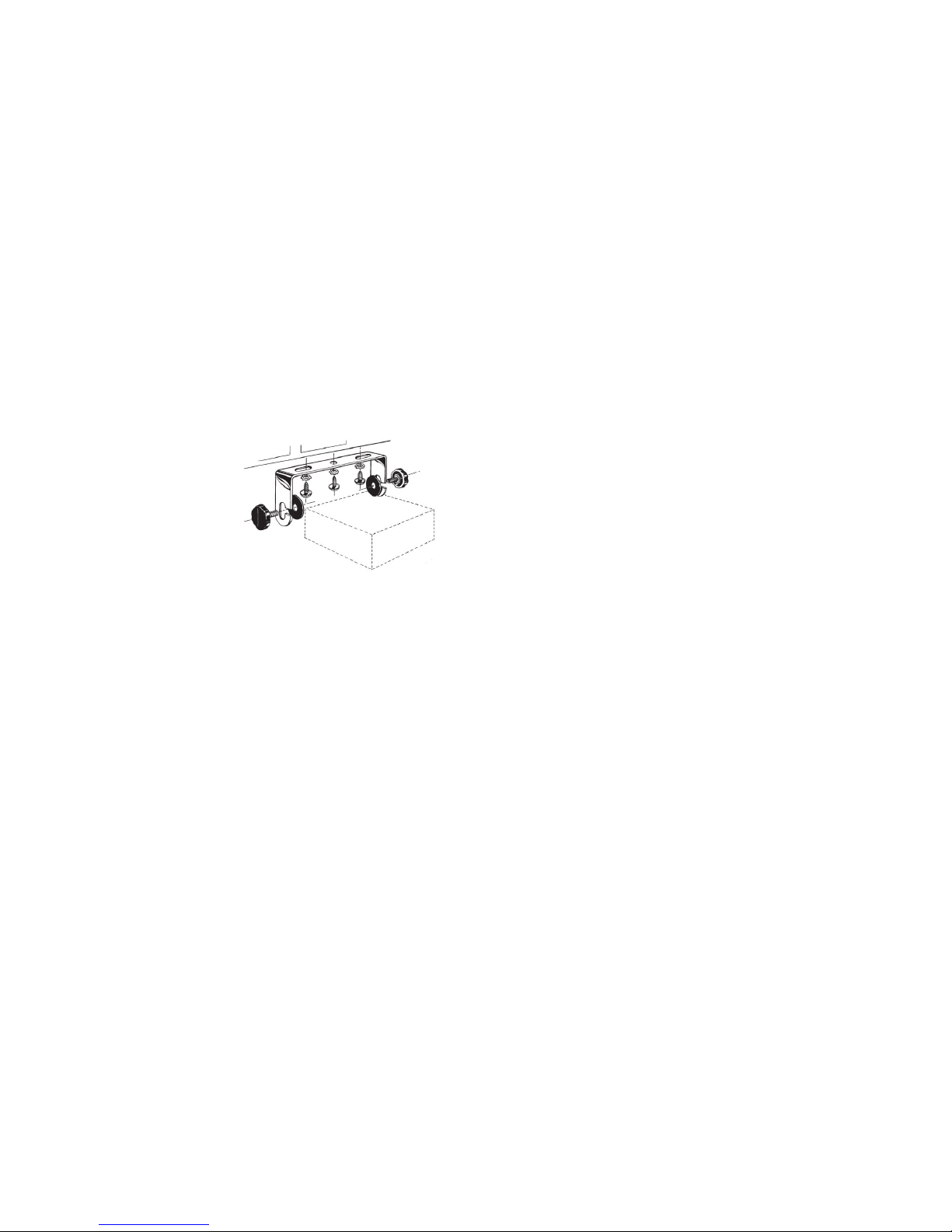
2. INSTALLATION
Before installing the main unit in the vehicle, please check and select
the most convenient position, in order that the radio will be easy to
reach and comfortable to operate without disturbing or interfering
driving. Use the supplied bracket and hardware to install the radio.
The bracket screws must be
well tightened to avoid loose-
ness as the vehicle vibrates.
The car mounting bracket
can be installed over or be-
low the radio and the radio
may be inclined as desired
according to the specific
type of installation (under
dashboard or track cabin roof installation).
2.1 INSTALLATION OF THE MAIN UNIT
Before connecting the radio to the vehicle electric system, please
make sure the radio is powered off with the OFF/VOL yknob com-
pletely turned anticlockwise at OFF position. The DC power cable of
the radio includes a fuse holder with fuse located on the red positive
(+) wire. Please connect the DC power cable to the vehicle electric
system with special attention to correct polarity, even if the radio is
protected against polarity inversion. Connect the red wire to the posi-
tive (+) pole and the black wire to the negative (-) pole of the vehicle
electric system. Please make sure that the wires and terminals are
firmly connected, to prevent cables from disconnecting or causing
short circuits.
2.2 INSTALLATION OF THE ANTENNA
A specic mobile antenna adjusted for 27 MHz frequency range must
be used. The antenna installation must be done by a qualied tech-
nician or service center. Please install the antenna carefully on the

p.6
3. TECHNICAL INDICATORS
General
Channels 40 AM/FM
Frequency range 26.960 – 27.400MHz
Frequency control P.L.L.
Frequency Tolerance ±0.005%
Operating temperature -20°/+55°C
DC input voltage 13.8Vdc ±15%
Size 115 (L) x 38 (A) x 150 (P) mm
Weight 0.8 kg
Receiver
System CPU controlled Double conversion super
IF 1° 10.7 MHz / 2° 450 KHz
Sensitivity -120dBm for 12dB SINAD (FM)
-107dBm for 12dB SINAD (AM)
Audio output @10% THD 2.5W at 8 ohm
Audio distortion <8% at 1 KHz
Image rejection 65dB
Adjacent channel 85dB
Signal ise ratio 45dB
Current drain 220mA (stand-by)
Transmitter
System CPU controlled P.L.L. synthesizer
Maximum RF power 4W at 13.2Vdc
Modulation 85% to 90% (AM)
2KHz ±0.2 KHz (FM)
ANT impedance 50 ohm unbalanced
Current drain 1500mA (at no modulation)
*Specications and features are subject to change without notice.

LT-298
High Quality AM/FM CB Radio
RoHS
Compliant
0700
Owner’s Manual
Bond Telecom Co. Ltd.
Website: www.luiton.com
Other manuals for LT-298
1
Table of contents
Other Luiton Radio manuals


