urmet domus 1068/005A Assembly instructions

DS1068-044 LBT21165
Mod.
1068
REMOTE MANAGED ALARM CONTROL PANELS
Ref. 1068/005A
Ref. 1068/010A
Ref. 1068/005A
Through the following QR Code, it is possible to download the eventual new version of the manual.
Ref. 1068/010A
INSTALLATION AND PROGRAMMING MANUAL
http://qrcode.urmet.com/default.aspx?prodUrmet=164750&lingua=en
http://qrcode.urmet.com/default.aspx?prodUrmet=165029&lingua=en

DS1068-044 2 LBT21165
TABLE OF CONTENTS (Control panel FW Rel.: 1.050 / KP FW Rel: 1.050)
INTRODUCTION ..................................................................................................................................................................8
Conformity with Standard EN50131-1.........................................................................................................................8
How the manual is organised ......................................................................................................................................9
CONVENTIONS ..........................................................................................................................................................9
GLOSSARY...............................................................................................................................................................10
1THE 1068/005A AND 1068/010A SYSTEMS............................................................................................................12
1.1 Main characteristic ........................................................................................................................................12
1.2 System Architecture......................................................................................................................................13
1.2.1 Architecture............................................................................................................................................................13
1.2.2 Data Bus ................................................................................................................................................................13
1.2.3 Maximum system size............................................................................................................................................14
1.3 System connectivity ......................................................................................................................................15
1.3.1 Connection with remote user..................................................................................................................................17
1.3.2 Remote user connection via Urmet Secure APP (Android –IOS)..........................................................................18
1.3.3 Remote user connection via a Tablet with 1068set Android App ...........................................................................19
1.3.4 Radio device connection ........................................................................................................................................19
1.3.5 Connection with an alarm reception centre ............................................................................................................20
1.4 System components......................................................................................................................................21
1.4.1 1068/005A Control panel........................................................................................................................................21
1.4.2 1068/010A Control panel........................................................................................................................................22
1.4.3 1068/021 LCD Command Keypad..........................................................................................................................23
1.4.4 1067/008A 8-input expansion module....................................................................................................................23
1.4.5 Housing box for expansion module 1067/017 ........................................................................................................24
1.4.6 1067/334 - 335 Electronic key reader.....................................................................................................................24
1.4.7 1067/332 Additional keys kit...................................................................................................................................25
1.4.8 1068/435 Proximity key reader...............................................................................................................................25
1.4.9 1068/432 Proximity key kit......................................................................................................................................26
1.4.10 1068/011 Radio module .........................................................................................................................................26
1.4.11 1068/458 GSM/GPRS module with vocal synthesis...............................................................................................27
1.4.12 1067/014 Remote GSM antenna............................................................................................................................27
1.4.13 1068/013 IP interface.............................................................................................................................................27
1.4.14 1068/017 Radio interface on Bus...........................................................................................................................28
1.4.15 1067/092 supplementary power supply with repeater ............................................................................................28
1.4.16 1068/002 IP POE Interface.....................................................................................................................................29
1.4.17 1068/027 7” Touch screen keypad .........................................................................................................................29
2DESIGN: CALCULATIONS AND TESTS..................................................................................................................30
2.1 Sizing of the power supplies and the batteries .............................................................................................30
2.1.1 Battery sizing..........................................................................................................................................................30
2.1.2 Calculation of the total absorption of the system....................................................................................................31
2.2 Cable Sizing..................................................................................................................................................31
2.2.1 Cables to be used, connections of the shields and installation ..............................................................................31
2.2.2 Sizing of the power supply cable............................................................................................................................32
2.2.3 Sizing the power supply and data transmission bus...............................................................................................33
2.2.4 Extending the bus with the repeater.......................................................................................................................34
2.2.5 Sizing of Input/Output connections.........................................................................................................................35
2.3 Control criteria of the mains power supply voltage.......................................................................................35
2.3.1 Blackout event........................................................................................................................................................35
2.3.2 Continued blackout alarm.......................................................................................................................................35
2.3.3 Restoration of the mains power supply ..................................................................................................................36
2.4 Battery management criteria.........................................................................................................................36
2.4.1 Controlling the battery with mains power supply absent.........................................................................................36
2.4.2 Battery test in presence of mains...........................................................................................................................36
2.5 Self-diagnostic functions ...............................................................................................................................36

DS1068-044 3 LBT21165
3INSTALLATION.........................................................................................................................................................37
3.1 Installation procedure....................................................................................................................................37
3.2 Wiring............................................................................................................................................................37
3.3 Preparing the 1068/005a –1068/010a control panel....................................................................................38
3.4 Installation of the 1068/005a –1068/010a control panels............................................................................40
3.4.1 Description of the main parts of the 1068/005A control panel................................................................................40
3.4.2 Description of the main parts of the 1068/010A control panel................................................................................42
3.4.3 Installing the 1068/011 Radio module....................................................................................................................44
3.4.4 Installing the 1068/013 IP module..........................................................................................................................44
3.4.5 Installing the 1068/002 IP POE interface................................................................................................................45
3.4.6 Installing the 1068/458 GSM/GPRS module with vocal synthesis..........................................................................47
3.5 Installation of the 1067/008A expansion.......................................................................................................50
3.6 Installation of the 1068/017 radio interface...................................................................................................51
3.7 Installation of the 1068/021 keypad ..............................................................................................................52
3.8 Installation of the 1068/027 keypad ..............................................................................................................54
3.9 Installation of the 1068/435 reader ...............................................................................................................55
3.10 Installation of the 1067/092 supplementary power supply (available only with 1068/010A control panel)...56
3.10.1 Fastening to the wall ..............................................................................................................................................56
3.10.2 Connecting the power supply and battery ..............................................................................................................56
3.10.3 The 1067/092 board...............................................................................................................................................57
3.11 Connections ..................................................................................................................................................59
3.11.1 Mains power supply line.........................................................................................................................................60
3.11.2 Connecting the data Bus........................................................................................................................................61
3.11.3 Connecting IP POE interface..................................................................................................................................62
3.11.4 Connecting the supplementary power supplies/repeater........................................................................................63
3.11.5 Connecting inputs...................................................................................................................................................64
3.11.6 Connecting outputs ................................................................................................................................................66
3.11.7 Connecting the cable for the service keypad..........................................................................................................68
3.11.8 Connecting the telephone communicator...............................................................................................................68
3.12 Example of connection diagram of 1068/005A control panel with N.C. inputs.............................................69
3.13 Example of connection diagram of 1068/010A control panel with N.C. inputs.............................................70
3.14 Example of connection diagram of 1068/005A control panel with single BAL. inputs..................................71
3.15 Example of connection diagram of 1068/010A control panel with single BAL. inputs..................................72
3.16 Example of connection diagram of 1068/005A control panel with double BAL. inputs.................................73
3.17 Example of connection diagram of 1068/010A control panel with double BAL. inputs.................................74
3.18 Example of connection diagram of 1068/010A control panel with double inputs .........................................75
3.19 Example of connection diagram of 1067/008A expansion with NC inputs ...................................................76
3.20 Example of connection diagram of 1067/008A expansion with SINGLE BAL. inputs ..................................77
3.21 Example of connection diagram of 1067/008A expansion with DOUBLE BAL. inputs.................................78
4COMMISSIONING.....................................................................................................................................................79
4.1 System power supply....................................................................................................................................79
4.2 Acquisitions of bus devices...........................................................................................................................80
4.2.1 Position of the programming buttons......................................................................................................................80
4.2.2 Procedure for acquiring the first keypad.................................................................................................................80
4.2.3 Procedure for acquiring bus devices (expansions and readers).............................................................................81
4.3 Using the service keypad..............................................................................................................................81
5SYSTEM COMMISSIONING.....................................................................................................................................82
5.1 Navigation menu ...........................................................................................................................................82
5.1.1 How to access menus............................................................................................................................................83
5.1.2 Free access menu..................................................................................................................................................83
5.1.3 Main Menu..............................................................................................................................................................84
5.2 How to enter alphanumeric characters .........................................................................................................85
5.3 How to enable the Installer............................................................................................................................85
5.4 How to enable the Technical Manager .........................................................................................................85

DS1068-044 4 LBT21165
5.5 How to select the language...........................................................................................................................86
5.6 LCD Info........................................................................................................................................................86
5.7 Date and time setting ....................................................................................................................................86
5.8 Zones programming......................................................................................................................................87
5.9 Wired input programming..............................................................................................................................87
5.9.1 Wired input encoding..............................................................................................................................................88
5.9.2 Input types..............................................................................................................................................................88
5.9.3 Wired input customisation ......................................................................................................................................89
5.9.4 Isolable...................................................................................................................................................................91
5.9.5 Auxiliary functions of intrusion inputs (Gong, Courtesy light and Door opener)......................................................92
5.9.6 Zone assignment type (AND / OR).........................................................................................................................92
5.9.7 AND inputs.............................................................................................................................................................92
5.9.8 Input programming procedure................................................................................................................................93
5.10 Wired input programming..............................................................................................................................94
5.10.1 Output encoding.....................................................................................................................................................94
5.10.2 Output types...........................................................................................................................................................95
5.10.3 Output assignment.................................................................................................................................................95
5.10.4 Electrical characteristics of the outputs ..................................................................................................................95
5.10.5 Output customisations............................................................................................................................................95
5.10.6 Output behaviour when the system is being serviced ............................................................................................98
5.10.7 Output programming procedure .............................................................................................................................99
5.11 Keypad programming..................................................................................................................................100
5.11.1 Function programming procedure ........................................................................................................................100
5.11.2 Zones assignment................................................................................................................................................101
5.11.3 Gong function.......................................................................................................................................................101
5.11.4 Entry time.............................................................................................................................................................101
5.11.5 Exit time ...............................................................................................................................................................102
5.11.6 Masking................................................................................................................................................................102
5.11.7 Name....................................................................................................................................................................102
5.11.8 Function key.........................................................................................................................................................102
5.12 Reader programming ..................................................................................................................................103
5.12.1 LED management ................................................................................................................................................103
5.12.2 Programming procedure.......................................................................................................................................103
5.13Keys ............................................................................................................................................................103
5.13.1 Key acquisition.....................................................................................................................................................104
5.13.2 Key deletion..........................................................................................................................................................104
5.13.3 Key configuration..................................................................................................................................................104
5.14 Advanced programming..............................................................................................................................105
5.14.1 Remote control system code................................................................................................................................105
5.14.2 Programming procedure.......................................................................................................................................105
5.15 General system parameters (timings).........................................................................................................106
5.15.1 Programming procedure Times and parameters..................................................................................................107
5.16 Phone dialer and IP interface......................................................................................................................107
5.16.1 Alarm and event notifications ...............................................................................................................................107
5.16.2 Phone numbers and IP addresses.......................................................................................................................107
5.16.3 Vocal messages...................................................................................................................................................107
5.16.4 SMS text messages .............................................................................................................................................108
5.16.5 GSM parameters..................................................................................................................................................108
5.16.6 GPRS parameters................................................................................................................................................108
5.16.7 GSM field test.......................................................................................................................................................109
5.16.8 IP parameters.......................................................................................................................................................109
5.16.9 IDP protocol..........................................................................................................................................................111
5.16.10 IDP/IP Protocol.....................................................................................................................................................111
5.16.11 Advanced .............................................................................................................................................................112
5.17 Time scheduler............................................................................................................................................113

DS1068-044 5 LBT21165
5.17.1 Operating principles .............................................................................................................................................113
5.17.2 Programming........................................................................................................................................................114
5.17.3 Deleting a command ............................................................................................................................................114
5.18 System Test ................................................................................................................................................115
5.18.1 Input test ..............................................................................................................................................................115
5.18.2 Output test............................................................................................................................................................115
5.18.3 Control panel battery test .....................................................................................................................................115
5.18.4 Call or SMS test ...................................................................................................................................................115
5.18.5 Push notification sending test...............................................................................................................................115
5.18.6 GSM Field Test ....................................................................................................................................................115
5.18.7 IP interface test ....................................................................................................................................................115
5.18.8 Supplementary power supply battery test (available only with 1068/010A control panel) ....................................115
5.18.9 System diagnostics ..............................................................................................................................................116
5.18.10 Final tests.............................................................................................................................................................116
5.19 User training................................................................................................................................................116
6PROGRAMMING WITH TABLET............................................................................................................................117
6.1 Prerequisites ...............................................................................................................................................117
6.1.1 Tablet Requirements............................................................................................................................................117
6.1.2 Enabling requirements .........................................................................................................................................117
6.1.3 File types..............................................................................................................................................................117
6.1.4 Saving data on Micro SD card..............................................................................................................................118
6.1.5 How to restore data on the control panel..............................................................................................................118
7MAINTENANCE MENU...........................................................................................................................................119
7.1 How to view device addresses....................................................................................................................119
7.2 How to view the firmware release of devices..............................................................................................119
7.3 How to upgrade bus device firmware from menu .......................................................................................119
7.3.1 Upgrade files........................................................................................................................................................119
7.3.2 Updating system firmware from keypad ...............................................................................................................120
7.3.3 System firmware upgrade from 1068set App .......................................................................................................121
7.4 Reset default...............................................................................................................................................122
7.5 Reset factory settings..................................................................................................................................122
7.6 System log...................................................................................................................................................122
7.6.1 How to interpret viewed data................................................................................................................................123
7.6.2 How to browse the System Log............................................................................................................................123
7.6.3 How to browse the EN50131 Event log (available only with 1068/010A control panel)........................................124
7.6.4 How to delete the System Log..............................................................................................................................124
7.6.5 How to delete the EN50131 Event log (available only with 1068/010A control panel)..........................................124
8TABLES...................................................................................................................................................................125
8.1 Vocal alarm messages and SMS................................................................................................................125
8.2 Alarm sending types....................................................................................................................................126
8.3 Remote control functions ............................................................................................................................126
8.4 Factory settings...........................................................................................................................................129
8.4.1 System code.........................................................................................................................................................129
8.4.2 Zones ...................................................................................................................................................................129
8.4.3 Users....................................................................................................................................................................129
8.4.4 Keys.....................................................................................................................................................................129
8.4.5 General parameters and Times............................................................................................................................130
8.4.6 Control panel inputs .............................................................................................................................................130
8.4.7 Control panel outputs ...........................................................................................................................................131
8.4.8 Expansion module inputs .....................................................................................................................................132
8.4.9 Expansion outputs................................................................................................................................................132
8.4.10 Keypad inputs.......................................................................................................................................................133
8.4.11 Radio module/interface inputs..............................................................................................................................133
8.4.12 Radio module/interface outputs (sirens)...............................................................................................................133
8.4.13 Reader inputs.......................................................................................................................................................133

DS1068-044 6 LBT21165
8.4.14 Keypad parameters..............................................................................................................................................134
8.4.15 Reader- zones assignment...................................................................................................................................134
8.4.16 Assignment of radio remote control keys .............................................................................................................134
8.4.17 Communicator parameters...................................................................................................................................135
8.4.18 Time scheduler.....................................................................................................................................................136
8.5 Time scheduler configuration......................................................................................................................136
9MAINTENANCE.......................................................................................................................................................138
9.1 Maintenance procedure ..............................................................................................................................138
9.1.1 Maintenance mode access...................................................................................................................................138
9.1.2 End of maintenance .............................................................................................................................................139
9.2 Adding a new bus device............................................................................................................................139
9.2.1 Procedure for acquiring bus devices (expansions, readers and radio interfaces) ................................................139
9.2.2 Keypad acquisition...............................................................................................................................................140
9.2.3 Touch keypad acquisition.....................................................................................................................................140
9.3 Replacing a radio device.............................................................................................................................142
9.4 Replacing a bus device...............................................................................................................................143
9.4.1 Replacing the Bus devices (expansions, readers and radio interfaces) ...............................................................143
9.4.2 Replacing the keypad...........................................................................................................................................143
9.5 Identifying a bus device...............................................................................................................................143
9.5.1 Interrogating a bus device....................................................................................................................................143
9.5.2 Searching for and identifying a device..................................................................................................................144
9.6 Deleting a bus device..................................................................................................................................144
9.7 Deleting 1068/017 RADIO INTERFACe or 1068/011 RADIO MODULe...................................................144
9.8 Enabling/disabling the 1068/011 radio module...........................................................................................145
9.9 Enabling/disabling the 1068/017 radio interface.........................................................................................145
9.9.1 Radio connection test...........................................................................................................................................145
9.10 Configuring radio parameters......................................................................................................................146
9.10.1 Device supervision...............................................................................................................................................146
9.10.2 Jamming...............................................................................................................................................................146
9.10.3 Enable..................................................................................................................................................................147
9.10.4 Module supervision ..............................................................................................................................................147
9.11 Acquisition of a new radio device................................................................................................................147
9.12 Deleting a radio device................................................................................................................................147
9.13 Reset factory settings..................................................................................................................................148
9.13.1 Software partial reset ...........................................................................................................................................148
9.13.2 Codes software reset ...........................................................................................................................................149
9.13.3 Radio module software reset................................................................................................................................149
9.13.4 Installer hardware code reset...............................................................................................................................149
9.13.5 1068/013 interface hardware reset.......................................................................................................................149
9.13.6 Hardware reset to factory settings........................................................................................................................149
9.13.7 Wired device hardware reset................................................................................................................................149
9.13.8 Wired keypad hardware reset...............................................................................................................................150
9.13.9 Replacing the battery ...........................................................................................................................................151
9.14 Turning off the entire system.......................................................................................................................151
10 TECHNICAL SPECIFICATIONS .............................................................................................................................152
10.1 1068/005A Control panel ............................................................................................................................152
10.2 1068/010A Control panel ............................................................................................................................153
10.3 1067/092 Supplementary power supply with repeater................................................................................154
10.4 1068/021 Command Keypad LCD..............................................................................................................155
10.5 1067/334 –1067/335 Electronic key reader ...............................................................................................155
10.6 1068/435 proximity reader ..........................................................................................................................155
10.7 1067/008A 8-input expansion module ........................................................................................................156
10.8 1068/458 GSM/GPRS module with vocal synthesis...................................................................................156
10.9 1068/013 IP interface..................................................................................................................................156

DS1068-044 7 LBT21165
10.10 1068/002 IP interface..............................................................................................................................157
10.11 1068/027 7”touch screen KEYPAD .......................................................................................................157

DS1068-044 8 LBT21165
INTRODUCTION
CONFORMITY WITH STANDARD EN50131-1
The EN50131-1 standard calls for the installation of a grade four intrusion alarm system, based on the level of risk determined in
function of the type of environment, of the value of the goods to be protected, and the typical intruder expected.
Grade 1: Low risk
It is expected that the intruders have little knowledge of intrusion alarm systems and have a limited range of tools that can be easily
obtained.
It is indicated for premises with contents of low value.
The system is simple and equipped with external and/or internal acoustic alarms, optical warnings, and eventually a telephonic
communicator for vocal messages to other people.
Grade 2: Average-low risk
It is expected that the intruders have limited knowledge of intrusion alarm systems and use some tools and portable instruments (for
example, a multimeter).
It is the minimum level that can be recognised by insurance companies. It involves mostly residential and commercial premises of low
value. The system can be connected with a Security Service.
Grade 3: Average-high risk
It is expected that the intruders have knowledge of intrusion alarm systems and have a full range of tools and portable electronic
equipment.
It is indicated for commercial and industrial premises, as well as for residential premises with a high value. The system is usually
connected with a Security Service.
Grade 4: High risk
To be used when security has the priority over all other factors. It is expected that the intruders have the skills and resources to plan a
detailed intrusion and have a complete set of tools available, including the means for substituting components of an intrusion alarm
system.
This is indicated for particularly sensitive premises, for example, banks.
WARNING! The grade of an intrusion alarm system is the one of its lowest grade component.
The EN50131-1 standard requires that the components of the intrusion alarm system are suitable to be used in one of the following
environmental classes, where Class I is the most moderate and class IV is the most severe.
Environmental class I –Indoors
Environmental influences normally present in closed environments, when the temperature is well-controlled (ex: in a residential or
commercial property).
The environment should not be subject to condensation and the temperature should vary between +5°C and +40°C with
an average relative humidity of about 75%.
Environmental class II –Indoors –General
Environmental influences normally present in closed environments, when the temperature has not been controlled (ex: in corridors,
other spaces or stairways where condensation may form on windows and in unheated areas used as a deposit or in warehouses
where heating is intermittent).
The environment should not be subject to condensation and the temperature should vary between -10°C and +40°C
with an average relative humidity of about 75%.
Environmental class III –Outdoors –Sheltered or indoors under extreme conditions
Environmental influences normally present outdoors when components of the intrusion alarm system are not totally exposed to
atmospheric agents or indoors, when the environmental conditions are extreme.
The environment should not be subject to condensation and the temperature should vary between -25°C and +50°C
with an average relative humidity of about 75%. For 30 days a year it is expected that the relative humidity will vary
between 85% and 95% without being subject to condensation.
Environmental class IV –Outdoors –General
Environmental influences normally present outdoors, when the components of the intrusion alarm system are completely exposed to
the elements.
The environment should not be subject to condensation and the temperature should vary between -25°C and +60°C
with an average relative humidity of about 75%. For 30 days a year it is expected that the relative humidity will vary
between 85% and 95% without being subject to condensation.

DS1068-044 9 LBT21165
HOW THE MANUAL IS ORGANISED
This manual is divided into chapters with topics organised sequentially to accompany each phase, from the design to the system
installation, programming and its successive maintenance, step by step.
Chapter 1 describes the 1068A series systems, theirs architecture and the devices that constitute it.
Chapter 2 provides useful information for designing and dimensioning alarm system components.
Chapter 3 explains how to install the control panel, the devices, the accessories, and how to connect them all together.
Chapter 4 illustrates the operations to be carried out to start up the system, before its programming.
Chapter 5 describes the programmings required to operate the system.
Chapter 6 illustrates how to program the system using a Tablet with Android 1068set App.
Chapter 7 describes the maintenance operations which do not require to physically operate on the system and that can be managed
via software.
Chapter 8 shows all the vocal messages (both pre-recorded and not) for the possible events and shows which messages can be
customised by recording a personal message over them.
Chapter 9 illustrates all the maintenance activities necessary to keep the alarm system functioning with perfect efficiency and provides
troubleshooting advice.
Chapter 10 contains the technical specifications of the control panel and the various devices.
The descriptions the end user will need to use the system are contained in the User's Manual.
CONVENTIONS
In this manual, some conventions have been used to distinguish between different types of information:
Warning! Warning messages highlight potential system damage, data loss or non-compliance with applicable
regulations.
Notes: notes contain important information, which may be useful for better use of the system.
This symbol indicates compliance with EN50131 grade 1.
This symbol indicates compliance with EN50131 grade 2.
This symbol indicates that the function or device does not comply with the EN50131 standard.
⎓
Direct power supply voltage.
~
Alternated power supply voltage.
Power supply unit with double isolation.
Refer to the device’s installation manual.

DS1068-044 10 LBT21165
GLOSSARY
AND
A logical function that requires that all the terms of the operation be true in order for the result to be true.
Open
An input is open when it receives a signal from a detector that is no longer in stand-by, for example, because an
attempted intrusion has been detected.
ATS
Acronym of Alarm Transmission System. Depending on the performances, they are capable of offering, they are
classified from ATS 1 to ATS 6, where ATS 1 is the simplest system and ATS 6 is the system with the highest
level of performance.
Communicator
A device capable of sending and transferring alarm signals and events via a phone line.
Default
The initial value of a device before configuration or when it is restored to the values set by the manufacturer.
DNS
Domain Transmission System, i.e. a system capable of resolving IP addresses of hosts in names and vice versa.
DTMF
Dual Tone Multi Frequency indicates the "tonal" mode of composition of a phone.
Entry
A point of access to rooms protected by the intrusion alarm system.
Event
A fact that occurs accidentally or when a specific condition is met, for example when a certain period of time has
passed.
Fieldbus (FB)
Fieldbus connecting Keypads (TS), Readers (LT) and Expansions (ER) connected to the microprocessor control
panel.
Physical address
(In)
Method used by the control panel to identify and locate inputs and outputs.
Logical address
(IN)
An alternative addressing method by which the control panel displays inputs and outputs and identifies them in
the alarm messages. The addresses can be freely assigned by the user.
Input
A point (terminal) for the physical connection of one or more detectors (usually sensors or contacts).
The input is defined as being open when the sensor signals that it is no longer in stand-by, for example because
it has verified an attempted intrusion.
OC
Open Collector transistor.
OR
A logical function that requires that at least one of the terms of operation be true for the result to be true.
Path
A set of one or more inputs that temporarily inhibit the signalling of sensor alarms connected to enable the entry
into or exit from a protected zone. The duration of the temporary disabling is defined as entry or exit time.
Protocol
Set of rules that govern the exchange or the transmission of data among devices.
RM
Reset Memory, is a signal (voltage) control that erases the memory of a detector and that can inhibit its
functioning, for example by putting it in stand-by.
SELV
Safety Extra-Low Voltage (rated voltage max 25 V~ and 50 V⎓).
Zone
Grouping of entries, exits, user codes, and keys that are associated with a space to be controlled.
Tamper
Protective micro-contact of a device.
Entry time
The time that the user has available from the moment in which he opens the first input to deactivate the desired
zones and prevent the generation of an intrusion alarm by the inputs programmed as "Path".
Delay time
The time that the user has available from the moment he opens the delayed input to the moment in which the
alarm is generated. It can be programmed for each individual input.
Exit time
The time that the user has available from the moment he activates the zone/s to exit the protected area and
prevent the generation of an intrusion alarm by the inputs configured as "Path".
Output
Point (terminal) for the physical connection of a device that enables the alarm system to act in the external
environment, e.g. by signalling an alarm (with a siren), communicating a system status (with a warning light or an
acoustic warning device), or activating electrical apparatus.

DS1068-044 11 LBT21165
IMPORTANT!
The factory control panel is released in operating mode according to
EN50131-1.
The 1068A series control panels have been built and designed to comply with the
requirements of the EN50131 standard.
1) The JP4 jumper must be closed in order to obtain the operating mode compliant
with EN50131 grade 1.
JP4 closed
2) To obtain the operating mode that does NOT comply with the EN50131 grade 1
standard, the JP4 jumper must be open.
JP4 open
IMPORTANT!
Incorrect selection of the JP4 jumper causes significant differences in operation.
IMPORTANT! System components (e.g. IP interface) must be connected to the control
panel when not powered (mains power and battery disconnected).
Quick consultation of topics
To know the main characteristics and components of the system...
see pages 12 to 29
How to size and check power supply units, cables and battery...
see pages 30 to 36
How to proceed with the installation of the control panel and its components...
see pages 37 to 78
How to commission the system before programming...
see pages 79 to 81
How to proceed with the programming for the commissioning of the system...
see pages 82 to 116
How to program your system with a Tablet with Android 1068set App...
see pages 117 to 118
How to proceed with system function maintenance operations managed via Software...
see pages 119 to 124
To know all the vocal messages, either pre-recorded and not, the expected events and how to customise
them…
see pages 125 to 137
How to proceed with the maintenance activities necessary to keep the system efficient and identify
faults...
see pages 138 to 151
To know the technical characteristics of the control panel and the various components of the system...
see pages 152 to 157

DS1068-044 12 LBT21165
1 THE 1068/005A AND 1068/010A SYSTEMS
This chapter describes the 1068A series systems.
More specifically, the following are analysed:
•The main characteristics of the system;
•The system architecture and the maximum dimension possible;
•The connectivity of system towards the outside;
•The various devices and accessories that make up the system.
1.1 MAIN CHARACTERISTIC
The wired intrusion alarm systems are modular system, suitable for small - mid-sized systems in residential, industrial, and service
settings.
Keypads, readers and expansions are connected to the control panel microprocessor by a proprietary field bus.
Detectors, sirens, and other signals are instead connected to the inputs and outputs present in the control panels and in other devices
connected to the bus. All the inputs can be configured for both type and customisation.
The system can be managed locally and remotely by means of a land line, cell phone, text message, and Internet.
The remote alarm notifications can be made with vocal message, text message, notification on smartphone or tablet, or numerical
protocol (for the connection to alarm reception units).
Other functions available are:
•Programming via tablet with Android 1068set App.
•Programming saved on micro SD Card, to transfer the programming between tablet and control unit or save a back-up copy.
•Firmware upgrade on devices through micro SD Card or IP 1068/013 interface.
•Technological signalling, that are activated by an event other than intrusion. Following an event of this type, the system can
command even specific actuations.
•Advanced vocal alarm calls that allow specific alarm messages to be sent for individual zones and/or inputs.
•Vocal help for remote management, used by the system to guide the user with vocal messages.
•Door opener, the electric lock can be controlled via the customized output, limiting access to specific areas only to authorised
personnel. Date, time and user who have commanded the opening are recorded in the control panel.
•Telephonic activation of an output without a connection charge. By taking advantage of the GSM phone number recognition
by the control panel, it is possible to generate a command on the specific output and close communications after the first 3-4
rings without charging for the call.
•Advanced automation. Through the time scheduler built into the control panel, it is possible to arrange a series of automatic and
repetitive commands weekly.
Moreover, there is an auxiliary function, which is not complying with current laws, that allows the guaranteed security of the system to
be increased easily and economically, without however replacing the dedicated systems:
•Emergency signalling, generating service signals when a dedicated button is pressed.
IMPORTANT! If the “emergency call” is required, it is necessary to have a remote emergency response system in
conformity with current legislation on this matter.

DS1068-044 13 LBT21165
1.2 SYSTEM ARCHITECTURE
1.2.1 Architecture
The following figure shows the devices that can be managed from the control panels 1068/005A and 1068/010A. For the
dimensioning of the system (combinations of devices and their maximum number) see the paragraph 1.2.3 Maximum system size.
Figure 1 –1068A series systems architecture
1.2.2 Data Bus
Control panel, keypads, readers and expansion modules are interconnected by a 4-wire bus.
The 4 wires transmit information among the various devices and supply 13.8 V⎓power from the control panels to the keypads,
readers, and expansion modules.
The use of the bus simplifies the wiring, given that, the information of a group of detectors located far from the control panel and
concentrated on a remote 1067/008A expansion module can be controlled with just 4 wires.
Note:
*1068/010A control panel = 10 inputs (20 in
Double Input mode), 1 SAB input, 2 relè outputs,
5 electric outputs.
** Valid only with 1068/010A control panel.
TOUCH SCREEN KEYPAD
1068/027
**
*

DS1068-044 14 LBT21165
1.2.3 Maximum system size
The table below shows the maximum number of keypads, readers, keys and expansions that can make up the alarm system.
Maximum limits are indicated for each single device and combined together when the system includes similar devices.
Example: the maximum number of readers that can be installed is 8, whether you use a single type or a mixed combination.
Device
1068/005A Control panel
1068/010A Control panel
Max Number
of each type
Max Number
of mixed combination
Max Number
of each type
Max Number
of mixed combination
1068/021 Command keypad (1)
8
------
8
------
1068/027 Touch screen keypad
1
------
1
------
1067/008A Expansion module
2
------
7
7
1067/092
Additional power supply with repeater
------
1068/011 Radio module
1
------
1
2
1068/017 Radio interface
1
2
1067/334 –335 Electronic key reader
8
8
8
8
1068/435 Transponder reader
8
8
1067/332 Electronic key
16
16
32
32
1068/432 Proximity key
16
32
Access codes (2)
19
------
35
35
Table 1 - Maximum size of 1068A series systems
1) If service keypad is used, it is not counted.
2) Of which 1 Master, 1 Installer, and 1 Technical Manager.
The table below shows the maximum number of inputs and outputs that a system of the maximum size can include.
Type
1068/005A Control panel
1068/010A Control panel
Max Number
Max Number
General inputs
21
66
5 + 16
10 + 56 (Single input mode)
----------
20 + 46 (Double input mode)
Anti-tampering inputs (SAB)
3
8
Relay outputs
4
9
Electric outputs
6
19
Radio sirens
4
8
Table 2 - Max number of inputs and outputs

DS1068-044 15 LBT21165
1.3 SYSTEM CONNECTIVITY
The alarm system can be connected to the external environment in different ways, sending signals and receiving commands.
Possible connection methods are:
•Mobile network (GSM). Requires optional 1068/458 interface.
•Internet or Ethernet - WiFi Domestic Network. Requires optional 1068/013 interface.
The tables below illustrate the functions available according to the means of communications used.
Description of
information transmitted
Means of communications used
GSM
(Vocal)
GSM
(SMS)
Internet and LAN
(Secure App and
1068set App)
GSM
(IDP)
Internet and
GPRS
(IDP/IP)
Sent by the control panel
Hold-up signalling
■
■
■
■
■
Intrusion signalling
■
■
■
■
■
Pre-alarm signalling
■
■
■
■
■
System setting/unsetting
signalling
■
■
■
■
■
Tamper signalling
■
■
■
■
■
False code signalling
■
■
■
■
■
Emergency alarm signalling
■
■
■
■
■
Fault signalling
■
■
■
■
■
Loss of mains signalling
■
■
■
■
■
Battery failure signalling
■
■
■
■
■
Maintenance signalling
■
■
■
■
■
Signalling of input isolation or
inhibition
■
■
■
■
■
Technological events signalling
■
■
■
■
■
SIM expiration warning
■
■
■

DS1068-044 16 LBT21165
Description of
information received
Means of communications used
GSM
(Incoming calls and
answering machine)
GSM
(Incoming calls
at no cost)
GSM
(Incoming SMS)
Internet and LAN
(Secure App and
1068set App)
Interaction with the control panel
Zone/s setting/unsetting
command
■
■
Controlled output
activation command
■
■
■
■
Controlled output
deactivation command
■
■
■
Input isolation/inclusion
command
■
■
System status report
request
■
■
Code and key
programming commands
■
Read event log command
■
DISCLAIMER
Urmet S.p.A. declines any and all responsibility concerning the unavailability, temporary or permanent, of the GSM/GPRS
phone network that may affect the making of calls or the sending of programmed messages.
Under conditions of a weak or disturbed field, there may be a decline in the performance of the GSM communication
vector.

DS1068-044 17 LBT21165
1.3.1 Connection with remote user
Figure 2 - Diagram of connection with remote user
From the control panel towards the remote user
The control panel, via outgoing calls, can:
•Send alarms and vocal signals (GSM network).
•Send alarms and signals via SMS (GSM network).
From the remote user towards the control panel
The User, via calls to the control panel, can:
•Use remote management with vocal guide and commands in DTMF for:
oInquire about the system status (armed/disarmed and anomalies present);
oActivate or deactivate zones;
oIsolate and reset inputs;
oRemotely control outputs (for gate opening devices, heating equipment, irrigation, etc.);
•Remote management with SMS for output remote controls (for gate opening devices, heating equipment, irrigation, etc.);
•“Zero cost” remote management through the Caller ID for output remote controls (gate opening devices, typically).
The GSM/GPRS 1068/458 interface is an optional item and can be used in control panels, either as an alternative or
together with the IP 1068/013 interface.
For further information, please see paragraph 3.11.8 Connecting the telephone communicator.
1068/458
1068/021
1068/021
1068/005A
1068/010A

DS1068-044 18 LBT21165
1.3.2 Remote user connection via Urmet Secure APP (Android –IOS)
From the control panel towards the remote user:
The control panel can send:
•Alarms and alerts with "Push" notifications.
From the remote user towards the control panel
The user through mobile devices and/or tablets with Urmet Secure App can:
•Fully or partially arm the system
•Disarm the system
•Receive notifications of any alarms
•Check the status of the alarms in real time
•Check the operating status of the system in real time
The IP 1068/013 interface is an optional item and can be used in control panels, either as an alternative or together with
the GSM/GPRS 1068/458 module.
Your smartphone must be equipped with the Urmet Secure App.
1068/013
1068/013
1068/005A
1068/010A
1068/005A
1068/010A

DS1068-044 19 LBT21165
1.3.3 Remote user connection via a Tablet with 1068set Android App
From the control panel towards the remote user
From the control panel, via outgoing notifications, alarms and signals can be sent directly to the tablet.
From the remote user towards the control panel
The user via mobile devices and/or tablets with 1068set App can:
•Activate all or part of the system
•Disarm the system
•Receive notifications of any alarms
•Check the status of the alarms in real time
•Check the operating status of the system in real time
•Perform system configuration and programming
The IP 1068/013 interface is an optional item and can be used in control panels, either as an alternative or together with
the GSM/GPRS 1068/458 module.
The tablet must be equipped with the 1068set Android App.
For further information, please see paragraph 3.11.8 Connecting the telephone communicator.
1.3.4 Radio device connection
1068/013
1068/005A
1068/010A
Radio
Module
1068/021
1068/021
1068/005A
1068/010A

DS1068-044 20 LBT21165
1.3.5 Connection with an alarm reception centre
1.
2.
1. With the IP 1068/013 interface, the control panel sends alarms and signals to the centre using the IDP/IP protocol.
2. With the GSM/GPRS 1068/458 module, the control panel sends alarms and signals to the centre using the IDP and IDP/IP
protocols.
(*) The GSM / GPRS 1068/458 module used with the 1068/010A control panel complies with the EN50131 Grade 2.
For further information, please see paragraph 3.11.8 Connecting the telephone communicator.
1068/013
IP
1068/005A
1068/010A
1068/458
GPRS
1068/005A
1068/010A
This manual suits for next models
2
Table of contents
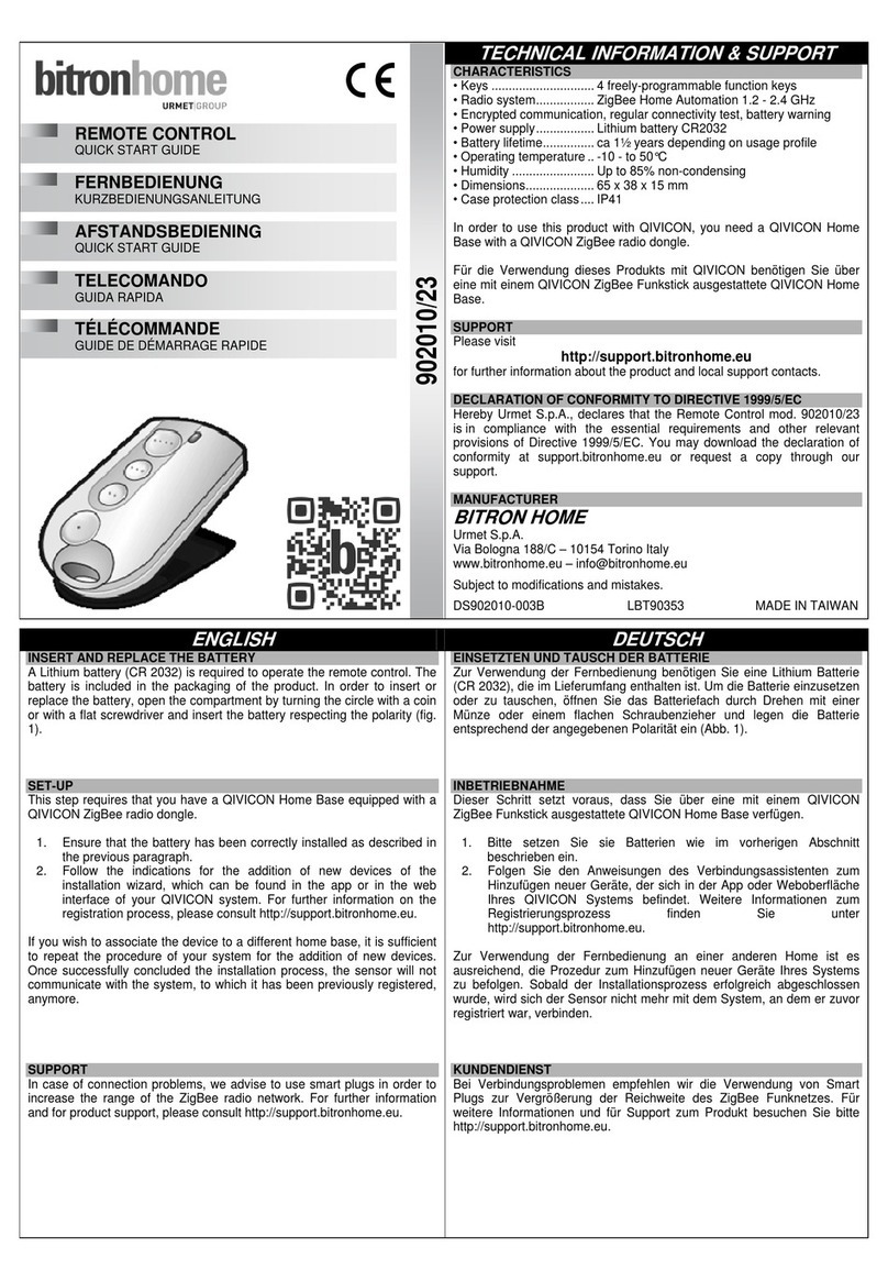
Other urmet domus Remote Control manuals

urmet domus
urmet domus bitronvideo AV2009/01 User manual

urmet domus
urmet domus Yokis MVR500MRP User manual

urmet domus
urmet domus 1051/035 Assembly instructions

urmet domus
urmet domus 1058/035 User manual

urmet domus
urmet domus Yokis TLC8C User manual

urmet domus
urmet domus BitronHome 902010/23 User manual