9
DS1783-002C
“B”
“A”
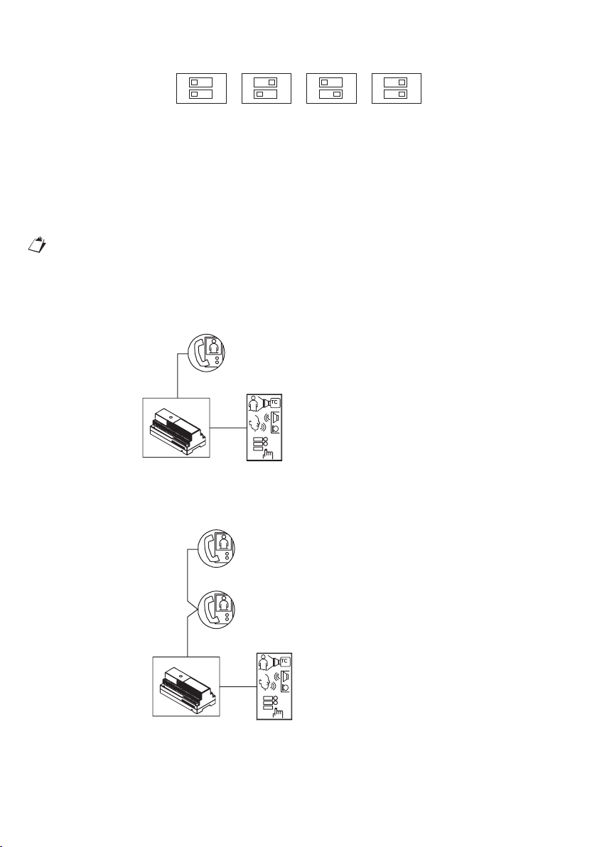
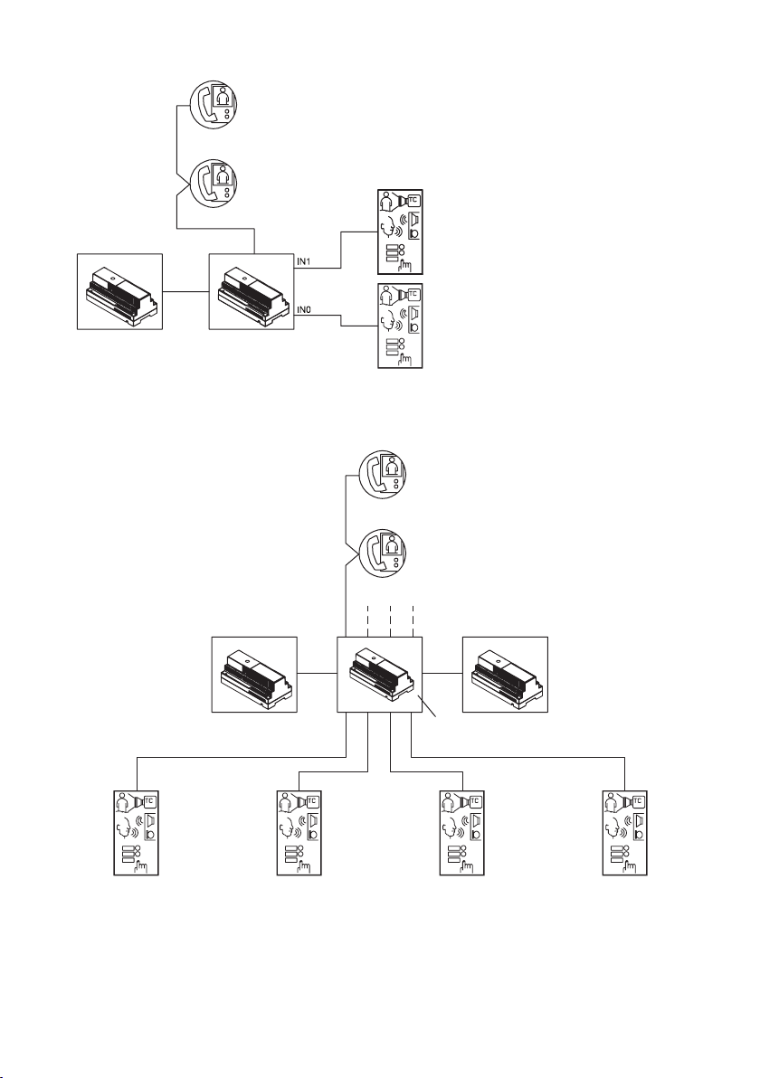
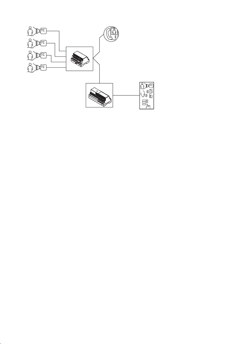
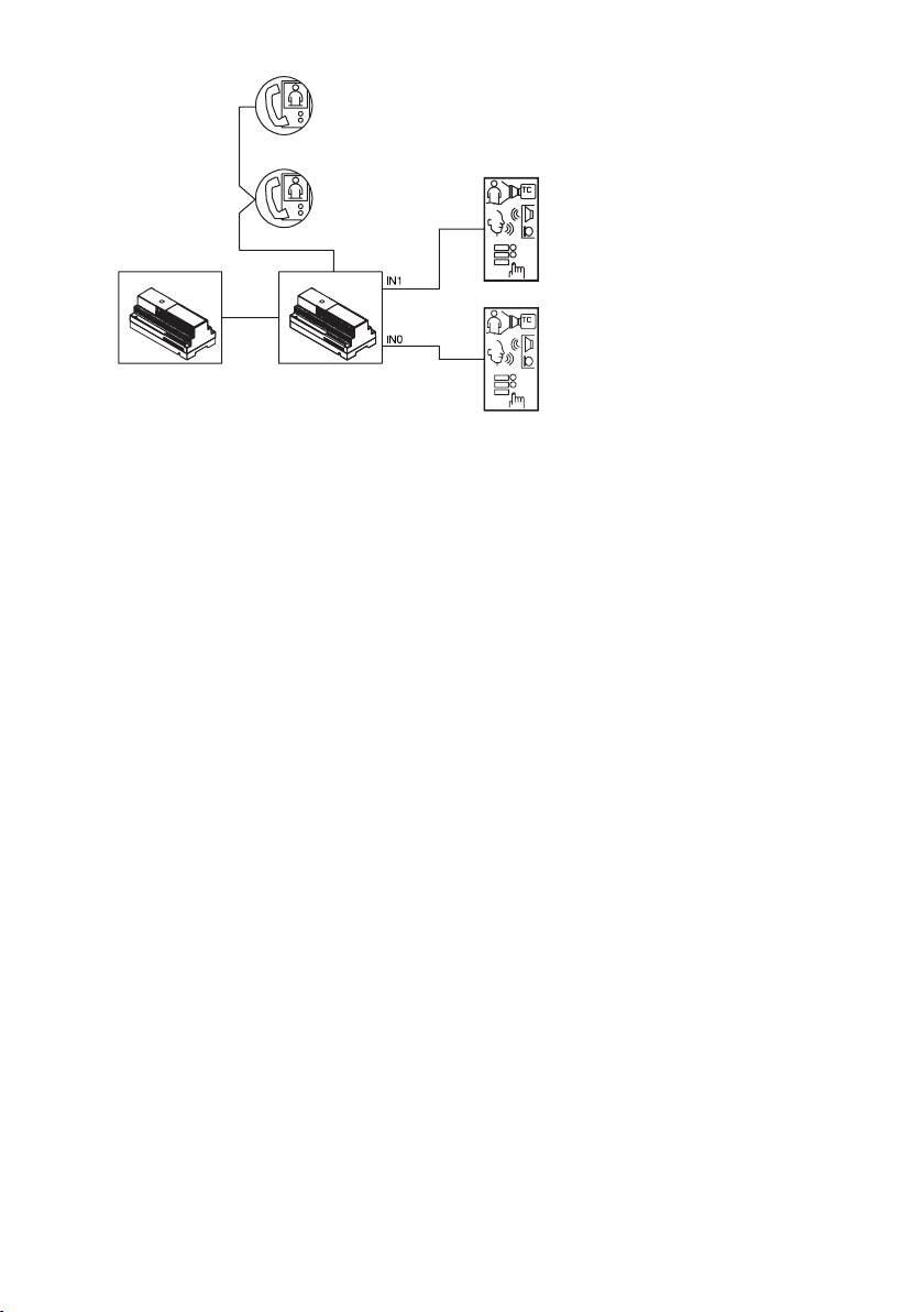
Alimentatore
2Voice
LINE 1
Interfaccia
di colonna
Sch. 1083/50
ID = 0
Posto interno
Utente 1
CODE = 1
INT = 0
Posto interno
Utente 0
CODE = 0
INT = 0
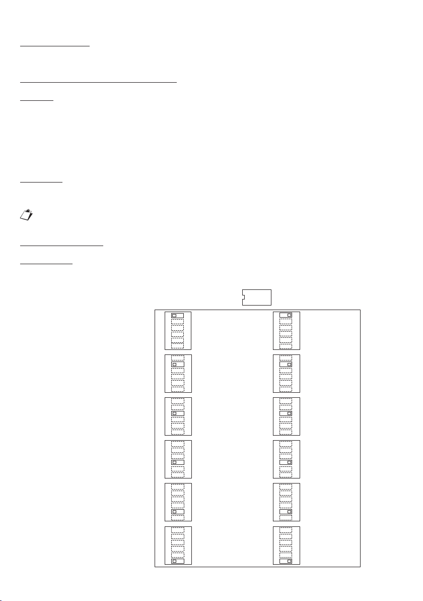
Postazione di chiamata
ID = 0
Aux dip 1 = ON (secondaria)
Aux dip 2 = ON (indirizzo 1)
Aux dip 6 = OFF (monofamiliare)
Chiama utente 1
Postazione di chiamata
ID = 0
Aux dip 1 = OFF (principale)
Aux dip 6 = OFF (monofamiliare)
Chiama utente 0
CANCELLAZIONE DEI DATI DI PROGRAMMAZIONE
Per cancellare tutti i dati impostati in configurazione avanzata procedere come segue:
Accedere alla configurazione avanzata (CONV TIME = 9).
Tenere premuto un qualsiasi tasto per almeno 5 s. Il posto esterno emette un avviso acustico per
confermare l’avvenuta cancellazione.
AZIONAMENTO ELETTROSERRATURA PEDONALE
I posti esterni hanno due morsetti per la gestione a scarica capacitiva dell’elettroserratura (SE-, SE+).
L’elettroserratura viene pilotata nei casi seguenti:
Ogni volta che viene premuto il pulsante androne (morsetti PA).
Alla ricezione del comando apriporta pedonale di un posto interno in funzione della configurazione del
dip-switch AUX relativo alla modalità di funzionamento “libero” o “sotto segreto” (vedere paragrafo
“Configurazione”).
Il tempo di attivazione dell’elettroserratura è programmabile tramite dip-switch “Door Time”.
AZIONAMENTO ELETTROSERRATURA PASSO CARRAIO
I posti esterni hanno due morsetti connessi ai contatti di un relè di normalmente aperto, utilizzabile come
comando di una centralina apricancello (1). Il relè viene pilotato per 1 s alla ricezione del comando apriporta
passo carraio di un posto interno in funzione della configurazione della modalità di funzionamento ‘libero’ o
‘sotto segreto’ come per l’elettroserratura pedonale.
(1) Il relè in oggetto NON è adattato a pilotaggio diretto di carichi di potenza, ma è utilizzabile esclusivamente
come relè di comando.
CARATTERISTICHE TECNICHE
Tensione di alimentazione (LINE): 36 - 48Vcc
Assorbimento a riposo: 45mA max
Assorbimento max (videochiamata e cartellini accesi): 250mA max
Temperatura di funzionamento: -10°C ÷ + 50°C
Conformità normativa: EN 61000-6-3, EN 61000-6-1
•
•
•
•