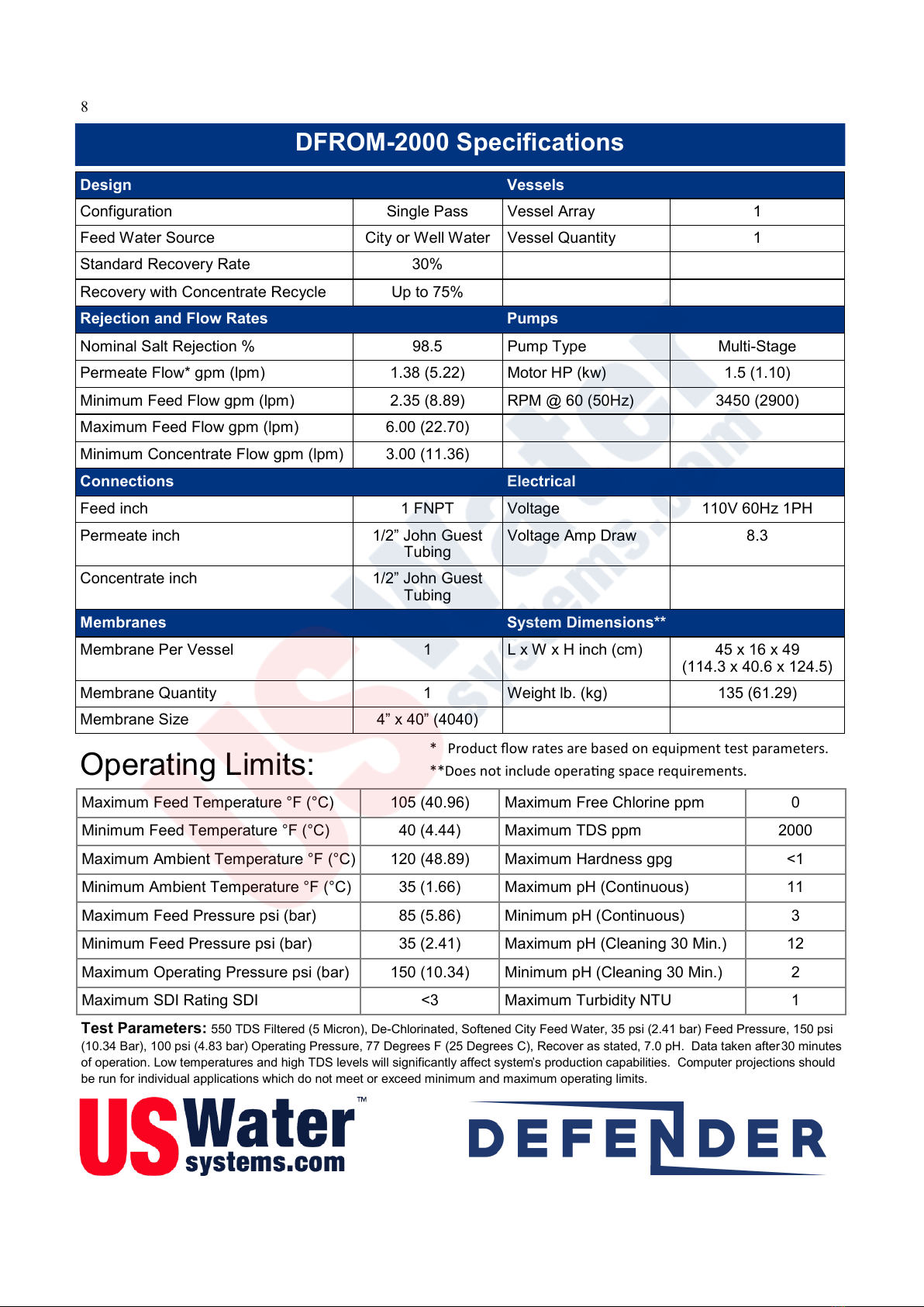
US Water Systems Defender 223-DFROM Series User manual

Owners Manual
Models 223-DFROM –XXXX
REVISION # 1.1
REVISION DATE: June 25, 2019
US Water Systems Corporate Office
1209 Country Club Road
Indianapolis, IN 46234
1-800-608-8792
Visit us online at
www.uswatersystems.com

2
Safety Guide
Be sure to check the entire RO system for any shipping damage or parts loss. Also note
damage to the shipping cartons. Contact US Water Systems at 1-800-608-8792 to report
any shipping damage within 24 hours of delivery. Claims made after 24 hours may not be
honored.
Unpacking / Inspection
Unpacking / Inspection 2
Safety Guide 2
Proper Installation 3
Component Identification 4
Specifications 8
Rejection, Recovery & Flow Rates 13
System Requirements and Guidelines 13
Electrical Connections 14
Pre-Filtration, Pump & Membranes 15
Tank Level & Pre-treatment Lockout Wiring 17
Anti-Scalant Filling and Settings 18
Glossary of Terms 19
RO Start-up 20
Operating Do’s and Don’ts, 21
Low Pressure Switch, Pump Throttle Valve & Adjustment of Throttle Valve 22
Membrane Removal and Replacement 23
Flushing the System 24
Temperature Correction Factors for Membranes 25
Flow Diagrams 26
Typical Layout Drawing 28
Controller Programming Instructions 29
Electrical Schematic 32
Warranty 33
Table of Contents
• Check and comply with provincial / state
and local codes. It may be mandatory that
these codes/laws be followed.
• Use care when handling the RO system.
• The RO System works on 110 or 220 volt-
60 Hz 1PH electrical power only.
• DO NOT exceed 150 psi on the pump or
membrane pressure gauge or damage or
injury could occur.

3
Proper Installation
This RO system must be properly installed and located in accordance with the
Installation Instructions before it is used or the warranty will be void.
Do not install or store where it will be ex-
posed to temperatures below freezing or ex-
posed to any type of weather. Water freez-
ing in the system will break it. Do not attempt
to treat water over 100°F.
Do not install in direct sunlight. Excessive
sun or heat may cause distortion or other
damage to non-metallic parts.
Properly ground to conform with all govern-
ing codes and ordinances.
Use only lead-free solder and flux for all
sweat-solder connections, as required by
state and federal codes.
Maximum allowable inlet water pressure is
125 psi. If daytime pressure is over 80 psi,
night time pressure may exceed the maxi-
mum. Use a pressure reducing valve (PRV)
to reduce the pressure.
RO membranes will degrade in the presence
of chlorine or chloramines. In these condi-
tions, it is wise to consider purchasing a
backwashing carbon filter system with a
chlorine reducing media. Contact US Water
Systems for Chlorine and Chloramine remov-
al equipment.
WARNING: Discard all unused parts and
packaging material after installation. Small
parts remaining after the installation could be
a choke hazard.
32° - 100° F
No Direct Sunlight
Conform to all
Governing Codes
125 Max. PSI
0 ppm Max. Chlorine &
Chloramine
Discard All
Unused Material

4
Component Identification
1. Solenoid Valve - Turns ON/OFF Feed Water Supply when the tank input circuit is opened
2. 5 Micron Sediment Pre-filter - Removes Sediment from the Feed Water
3. Filter IN Pressure Gauge - Monitors Feed Water Pressure prior to the Pre-filters
4. Pump Pressure Gauge- Monitors the Membrane/Pump pressure during operation. WARNING! Do not ex-
ceed 150psi.

5
Component Identification
5. Computer Control - The Minitrol Controls ON/OFF Function as well as Fail Safe Switches.
6. Recycle/Recirculation Valve - Controls the amount of Concentrate Water that is Fed back to the Mem-
branes for Recycle
7. Concentrate/Waste Valve - Controls the amount of Concentrate Water going to the drain for waste.
8. Pump and Motor - Boosts the Feed Water Pressure to the Membranes

6
Component Identification
9. Throttle Valve - Adjusts the Boost Pressure to the Membranes. WARNING! Do not exceed 150psi.
10. Permeate/Product Flow Meter - Monitors the amount of Permeate Water going to the storage or distribution
system.
11. Concentrate Flow Meter - Monitors the amount of Concentrate Water going to drain.
12. Recycle/Recirculation Flow Meter - Monitors the amount of Concentrate Water being recycled to the Mem-
branes.

7
Component Identification
13. Low Pressure Switch - Shuts the system down as a fail safe in a Low Feed Water Pressure condition.
This pressure switch is in the RO controller.
14. Membrane Pressure Vessels - Holds the Membranes
15. Power Supply Cord
16. Injection Pump Electrical Connection
17. Tank Level or Pressure Shutoff Connections
WARNING! This input is a NO VOLTAGE dry contact. DO NOT
apply voltage to this input!

8
DFROM-2000 Specifications
Design Vessels
Configuration Single Pass Vessel Array 1
Feed Water Source City or Well Water Vessel Quantity 1
Standard Recovery Rate 30%
Recovery with Concentrate Recycle Up to 75%
Rejection and Flow Rates Pumps
Nominal Salt Rejection % 98.5 Pump Type Multi-Stage
Permeate Flow* gpm (lpm) 1.38 (5.22) Motor HP (kw) 1.5 (1.10)
Minimum Feed Flow gpm (lpm) 2.35 (8.89) RPM @ 60 (50Hz) 3450 (2900)
Maximum Feed Flow gpm (lpm) 6.00 (22.70)
Minimum Concentrate Flow gpm (lpm) 3.00 (11.36)
Connections Electrical
Feed inch 1 FNPT Voltage 110V 60Hz 1PH
Permeate inch 1/2” John Guest
Tubing
Voltage Amp Draw 8.3
Concentrate inch 1/2” John Guest
Tubing
Membranes System Dimensions**
Membrane Per Vessel 1L x W x H inch (cm) 45 x 16 x 49
(114.3 x 40.6 x 124.5)
Membrane Quantity 1Weight lb. (kg) 135 (61.29)
Membrane Size 4” x 40” (4040)
* Product ow rates are based on equipment test parameters.
**Does not include operang space requirements.
Operating Limits:
Maximum Feed Temperature °F (°C) 105 (40.96) Maximum Free Chlorine ppm 0
Minimum Feed Temperature °F (°C) 40 (4.44) Maximum TDS ppm 2000
Maximum Ambient Temperature °F (°C) 120 (48.89) Maximum Hardness gpg <1
Minimum Ambient Temperature °F (°C) 35 (1.66) Maximum pH (Continuous) 11
Maximum Feed Pressure psi (bar) 85 (5.86) Minimum pH (Continuous) 3
Minimum Feed Pressure psi (bar) 35 (2.41) Maximum pH (Cleaning 30 Min.) 12
Maximum Operating Pressure psi (bar) 150 (10.34) Minimum pH (Cleaning 30 Min.) 2
Maximum SDI Rating SDI <3 Maximum Turbidity NTU 1
Test Parameters: 550 TDS Filtered (5 Micron), De-Chlorinated, Softened City Feed Water, 35 psi (2.41 bar) Feed Pressure, 150 psi
(10.34 Bar), 100 psi (4.83 bar) Operating Pressure, 77 Degrees F (25 Degrees C), Recover as stated, 7.0 pH. Data taken after 30 minutes
of operation. Low temperatures and high TDS levels will significantly affect system’s production capabilities. Computer projections should
be run for individual applications which do not meet or exceed minimum and maximum operating limits.

9
DFROM-4000 Specifications
Design Vessels
Configuration Single Pass Vessel Array 1:1
Feed Water Source City or Well Water Vessel Quantity 2
Standard Recovery Rate 48%
Recovery with Concentrate Recycle Up to 75%
Rejection and Flow Rates Pumps
Nominal Salt Rejection % 98.5 Pump Type Multi-Stage
Permeate Flow* gpm (lpm) 2.78 (10.52) Motor HP (kw) 1.5 (1.10)
Minimum Feed Flow gpm (lpm) 7.00 (26.50) RPM @ 60 (50Hz) 3450 (2900)
Maximum Feed Flow gpm (lpm) 9.00 (34.07)
Minimum Concentrate Flow gpm (lpm) 3.00 (11.36)
Connections Electrical
Feed inch 1 FNPT Voltage 110V 60Hz 1PH
Permeate inch 1/2” John Guest
Tubing
Voltage Amp Draw 8.3
Concentrate inch 1/2” John Guest
Tubing
Membranes System Dimensions**
Membrane Per Vessel 1L x W x H inch (cm) 45 x 16 x 49
(114.3 x 40.6 x 124.5)
Membrane Quantity 2Weight lb. (kg) 135 (61.29)
Membrane Size 4” x 40” (4040)
* Product ow rates are based on equipment test parameters.
**Does not include operang space requirements.
Operating Limits:
Maximum Feed Temperature °F (°C) 105 (40.96) Maximum Free Chlorine ppm 0
Minimum Feed Temperature °F (°C) 40 (4.44) Maximum TDS ppm 2000
Maximum Ambient Temperature °F (°C) 120 (48.89) Maximum Hardness gpg <1
Minimum Ambient Temperature °F (°C) 35 (1.66) Maximum pH (Continuous) 11
Maximum Feed Pressure psi (bar) 85 (5.86) Minimum pH (Continuous) 3
Minimum Feed Pressure psi (bar) 35 (2.41) Maximum pH (Cleaning 30 Min.) 12
Maximum Operating Pressure psi (bar) 150 (10.34) Minimum pH (Cleaning 30 Min.) 2
Maximum SDI Rating SDI <3 Maximum Turbidity NTU 1
Test Parameters: 550 TDS Filtered (5 Micron), De-Chlorinated, Softened City Feed Water, 35 psi (2.41 bar) Feed Pressure, 150 psi
(10.34 Bar), 100 psi (4.83 bar) Operating Pressure, 77 Degrees F (25 Degrees C), Recover as stated, 7.0 pH. Data taken after 30 minutes
of operation. Low temperatures and high TDS levels will significantly affect system’s production capabilities. Computer projections should
be run for individual applications which do not meet or exceed minimum and maximum operating limits.

10
DFROM-6000 Specifications
Design Vessels
Configuration Single Pass Vessel Array 1:1:1
Feed Water Source City or Well Water Vessel Quantity 3
Standard Recovery Rate 53%
Recovery with Concentrate Recycle Up to 75%
Rejection and Flow Rates Pumps
Nominal Salt Rejection % 98.5 Pump Type Multi-Stage
Permeate Flow* gpm (lpm) 4.16 (15.80) Motor HP (kw) 1.5 (1.12)
Minimum Feed Flow gpm (lpm) 7.16 (27.20) RPM @ 60 (50Hz) 3450 (2900)
Maximum Feed Flow gpm (lpm) 14.00 (53.00)
Minimum Concentrate Flow gpm (lpm) 3.00 (11.36)
Connections Electrical
Feed inch 1 FNPT Voltage 220V 60Hz 1PH
Permeate inch 1/2” John Guest
Tubing
Voltage Amp Draw 8.3
Concentrate inch 1/2” John Guest
Tubing
Membranes System Dimensions**
Membrane Per Vessel 1L x W x H inch (cm) 30 x 38 x 47
(76 x 96 x 119)
Membrane Quantity 3Weight lb. (kg) 250 (61.29)
Membrane Size 4” x 40” (4040)
* Product ow rates are based on equipment test parameters.
**Does not include operang space requirements.
Operating Limits:
Maximum Feed Temperature °F (°C) 85 (29.00) Maximum Free Chlorine ppm 0
Minimum Feed Temperature °F (°C) 40 (4.44) Maximum TDS ppm 2000
Maximum Ambient Temperature °F (°C) 120 (48.89) Maximum Hardness gpg <1
Minimum Ambient Temperature °F (°C) 40 (4.44) Maximum pH (Continuous) 11
Maximum Feed Pressure psi (bar) 85 (5.86) Minimum pH (Continuous) 5
Minimum Feed Pressure psi (bar) 35 (2.41) Maximum pH (Cleaning 30 Min.) 12
Maximum Operating Pressure psi (bar) 150 (10.34) Minimum pH (Cleaning 30 Min.) 2
Maximum SDI Rating SDI <3 Maximum Turbidity NTU 1
Test Parameters: 550 TDS Filtered (5 Micron), De-Chlorinated, Softened City Feed Water, 35 psi (2.41 bar) Feed Pressure, 150 psi
(10.34 Bar), 100 psi (4.83 bar) Operating Pressure, 77 Degrees F (25 Degrees C), Recover as stated, 7.0 pH. Data taken after 30 minutes
of operation. Low temperatures and high TDS levels will significantly affect system’s production capabilities. Computer projections should
be run for individual applications which do not meet or exceed minimum and maximum operating limits.

11
DFROM-8000 Specifications
Design Vessels
Configuration Single Pass Vessel Array 1:1:1:1
Feed Water Source City or Well Water Vessel Quantity 4
Standard Recovery Rate 62%
Recovery with Concentrate Recycle Up to 75%
Rejection and Flow Rates Pumps
Nominal Salt Rejection % 98.5 Pump Type Multi-Stage
Permeate Flow* gpm (lpm) 5.56 (21.13) Motor HP (kw) 3.0 (2.24)
Minimum Feed Flow gpm (lpm) 8.56 (32.53)
Maximum Feed Flow gpm (lpm) 14.00 (53.00)
Minimum Concentrate Flow gpm (lpm) 3.00 (11.36)
Connections Electrical
Feed inch 1 FNPT Voltage 220V 60Hz 1PH
Permeate inch 1/2” John Guest
Tubing
Voltage Amp Draw 10.1
Concentrate inch 1/2” John Guest
Tubing
Membranes System Dimensions**
Membrane Per Vessel 1L x W x H inch (cm) 30 x 38 x 47
(76 x 96 x 119)
Membrane Quantity 4Weight lb. (kg) 242 (109.8)
Membrane Size 4” x 40” (4040)
* Product ow rates are based on equipment test parameters.
**Does not include operang space requirements.
Operating Limits:
Maximum Feed Temperature °F (°C) 85 (29.00) Maximum Free Chlorine ppm 0
Minimum Feed Temperature °F (°C) 40 (4.44) Maximum TDS ppm 2000
Maximum Ambient Temperature °F (°C) 120 (48.89) Maximum Hardness gpg <1
Minimum Ambient Temperature °F (°C) 40 (4.44) Maximum pH (Continuous) 11
Maximum Feed Pressure psi (bar) 85 (5.86) Minimum pH (Continuous) 5
Minimum Feed Pressure psi (bar) 35 (2.41) Maximum pH (Cleaning 30 Min.) 12
Maximum Operating Pressure psi (bar) 150 (10.34) Minimum pH (Cleaning 30 Min.) 2
Maximum SDI Rating SDI <3 Maximum Turbidity NTU 1
Test Parameters: 550 TDS Filtered (5 Micron), De-Chlorinated, Softened City Feed Water, 35 psi (2.41 bar) Feed Pressure, 150 psi
(10.34 Bar), 100 psi (4.83 bar) Operating Pressure, 77 Degrees F (25 Degrees C), Recover as stated, 7.0 pH. Data taken after 30 minutes
of operation. Low temperatures and high TDS levels will significantly affect system’s production capabilities. Computer projections should
be run for individual applications which do not meet or exceed minimum and maximum operating limits.

12
DFROM-12,000 Specifications
Design Vessels
Configuration Single Pass Vessel Array 2:2:2
Feed Water Source City or Well Water Vessel Quantity 6
Standard Recovery Rate 62%
Recovery with Concentrate Recycle Up to 75%
Rejection and Flow Rates Pumps
Nominal Salt Rejection % 98.5 Pump Type Multi-Stage
Permeate Flow* gpm (lpm) 8.33 (31.67) Motor HP (kw) 3.0 (2.24)
Minimum Feed Flow gpm (lpm) 15.56 (59.13)
Maximum Feed Flow gpm (lpm) 18.00 (68.4)
Minimum Concentrate Flow gpm (lpm) 6.00 (22.8)
Connections Electrical
Feed inch 1 FNPT Voltage 220V 60Hz 1PH
Permeate inch 1 FNPT Voltage Amp Draw 10.1
Concentrate inch 1 FNPT
Membranes System Dimensions**
Membrane Per Vessel 1L x W x H inch (cm) 50 x 30 x 50
(127 x 76 x 127)
Membrane Quantity 6Weight lb. (kg) 265 (113)
Membrane Size 4” x 40” (4040)
* Product ow rates are based on equipment test parameters.
**Does not include operang space requirements.
Operating Limits:
Maximum Feed Temperature °F (°C) 85 (29.00) Maximum Free Chlorine ppm 0
Minimum Feed Temperature °F (°C) 40 (4.44) Maximum TDS ppm 2000
Maximum Ambient Temperature °F (°C) 120 (48.89) Maximum Hardness gpg <1
Minimum Ambient Temperature °F (°C) 40 (4.44) Maximum pH (Continuous) 11
Maximum Feed Pressure psi (bar) 85 (5.86) Minimum pH (Continuous) 5
Minimum Feed Pressure psi (bar) 35 (2.41) Maximum pH (Cleaning 30 Min.) 12
Maximum Operating Pressure psi (bar) 150 (10.34) Minimum pH (Cleaning 30 Min.) 2
Maximum SDI Rating SDI <3 Maximum Turbidity NTU 1
Test Parameters: 550 TDS Filtered (5 Micron), De-Chlorinated, Softened City Feed Water, 35 psi (2.41 bar) Feed Pressure, 150 psi
(10.34 Bar), 100 psi (4.83 bar) Operating Pressure, 77 Degrees F (25 Degrees C), Recover as stated, 7.0 pH. Data taken after 30 minutes
of operation. Low temperatures and high TDS levels will significantly affect system’s production capabilities. Computer projections should
be run for individual applications which do not meet or exceed minimum and maximum operating limits.

13
Rejection, Recovery & Flow Rates
The US Water Systems DEFENDER reverse osmosis systems are designed to produce permeate water at the
capacities indicated by the suffix in the system’s name under the conditions listed above. For example, the DE-
FENDER-4000 produces 4000 gallons per day of permeate water at the listed operating test conditions.
The amount of total dissolved solids (TDS) rejected by the membrane is expressed as a percentage. For exam-
ple, a 98.5% rejection rate means that 98.5% of total dissolved solids do not pass through the membrane. To
calculate the % rejection, use the following formula:
% Rejection = [(Feed TDS – Product TDS) / Feed TDS] x 100
Example:
98.5% = [(550-8.25)/550] x 100
NOTE: ALL TDS FIGURES MUST BE EXPRESSED IN THE SAME UNITS, TYPICALLY PARTS PER MIL-
LION (PPM) OR MILLIGRAMS PER LITER (MG/L).
The DEFENDER reverse osmosis systems are designed to reject up to 98.5% NaCl, unless computer projec-
tions have been provided or stated otherwise.
The amount of permeate water recovered for use is expressed as a percentage. To calculate % recovery, use
the following formula:
% Recovery = (Product Water Flow Rate / Feed Water Flow Rate) x 100
Example:
40% = (2.78/7.0) x 100
NOTE: ALL FLOW RATES MUST BE EXPRESSED IN THE SAME UNITS, TYPICALLY GALLONS PER MI-
NUTE (GPM).
System Connections, Requirements and Guidelines
PLUMBING
The membranes and high pressure pumps used on Defender systems require a continuous flow of water with a
minimum feed pressure of 35 psi, not to exceed 105 F while the system is running.
FEED WATER CONNECTION
1. Locate the 1” FNPT inlet connection on the sediment filter hous-
ing.
2. Attach the inlet piping to the 1” FNPT Filter housing inlet.
NOTE: FEED LINE MUST BE MINIMUM 3/4” INCH ON THE
2000 AND 4000 GPD SYSTEM. FEED LINE MUST
BE 1” ON THE 8000 AND 12,000 GPD SYSTEMS.

14
System Connections, Requirements and Guidelines
PERMEATE (PRODUCT WATER) CONNECTION
1. Locate the 1/2” tubing labeled permeate and attach to the bulkhead in the top of the storage tank. Ensure
that the permeate water can flow freely with no backpressure. Backpressure can cause irreversible damage
to the membrane elements. The 12,000 GPD system should use 3/4”-1” hard piping to the tank.
NOTE: ALL PERMEATE PLUMBING SHOULD BE DONE WITH PLASTIC OR STAINLESS STEEL. SOFT
METALS WILL LEACH INTO THE WATER STREAM. CPVC, PVC, PEX AND STAINLESS STEEL
ARE THE MOST COMMONLY USED MATERIAL.
CAUTION: THE PH OF THE REVERSE OSMOSIS PERMEATE WATER WILL TYPICALLY BE 1-2 POINTS
LOWER THAN THE FEED WATER PH. A LOW PH CAN BE VERY AGGRESSIVE TO SOME
PLUMBING MATERIALS SUCH AS COPPER PIPING.
CONCENTRATE (WASTE WATER) CONNECTION
1. Locate the 1/2” tubing labeled concentrate and attach/convey to a drain. Run the concentrate line to an open
drain in a free and unrestricted manner (no backpressure). It is recommended that an air gap be maintained
on the drain line to prevent possible bacterial contamination. The 12,000 GPD unit will require a 3/4”-1” hard
pipe to the drain.
CAUTION: ANY RESTRICTIONS OR BLOCKAGE IN THE DRAIN LINE CAN CAUSE BACKPRESSURE,
WHICH WILL INCREASE THE SYSTEM’S OPERATING PRESSURE. THIS CAN RESULT IN
DAMAGE TO THE SYSTEM’S MEMBRANES AND COMPONENTS.
Electrical Connections
Main System Power
The main power on the Defender system is available in 110 and 220 Volt, 60 Hertz, 1 Phase. Each Defender
system is equipped with a 5 foot electrical cord. This can be hardwired in a disconnect box or an outlet box can
be installed that matches the cord end for the respective voltage. This should be powered by an isolated 20
amp breaker. If the 220V Defender is purchased and Neutral wire must be supplied with the load legs and earth
ground.
Optional Anti-Scalant Connection
If the optional anti-scalant injection system was purchase the electrical connection on the injection pump will
plug into female power cord on the unit labeled “Dosing Pump”.
NOTE: If the anti-scalant option was purchases the injection check valve that comes with the anti-
scalant pump should be put in the injection tee on the sediment filter outlet plumbing. There is a
1/2” plug that must be removed and the injection check valve can be installed.
BE SURE to Teflon tape the injection check valve threads before installing it in the tee fitting.
PERMEAT FLUSH CONNECTION (OPTIONAL)
1. Locate the 1/2” solenoid valve on the system. Connect a pressurized 1/2” pipe to the solenoid valve from
permeate supply pump after the storage tank. This will provide clean permeate water to flush the mem-
branes once the RO system has shut down.

15
Pre-Filtration
The DEFENDER systems do not include pre-filtration. It is VERY important to have pre-filtration before the RO
system to ensure longevity and that damage will not occur to the unit. A water test of the feed water is used to
determine the proper pretreatment equipment. Contact US Water Systems for help determining what pre-
treatment equipment is required. 1-800-608-8792.
NOTE: THE SYSTEM MUST BE OPERATED ON FILTERED WATER ONLY. 99.9% OF ALL RO APPLICA-
TIONS REQUIRE SOME FORM OF PRETREATMENT. SYSTEM OPERATED USING UNTREATED
WATER WILL HAVE PREMATURE MEMBRANE FAILURES. MEMBRANE FAILURES DUE TO IM-
PROPER PRETREATMENT ARE NOT COVERED UNDER WARRANTY.
Pump
The pump type used on the DEFENDER systems is multi-stage centrifugal carbon steel pumps.
Follow these guidelines to ensure proper operation of the pump:
• The pump must NEVER be run dry. Operating the pump without sufficient feed water will damage the
pump.
• ALWAYS feed the pump with filtered water. The pump is susceptible to damage from sediment and debris.
NOTE: THE FEED WATER PRESSURE MUST NOT FALL BELOW 30 PSI WHILE THE SYSTEM IS RUN-
NING. THE SYSTEM WILL SHUTDOWN FOR A LOW PRESSURE FAULT IF A PRESSURE >30 PSI
CANNOT BE MAINTAINED. DO NOT ATTEMPT TO ADJUST THE PRESSURE SWITCH. THE
PROPER FIX FOR THIS PROBLEM IS TO INCREASE THE FEED PRESSURE WITH A BOOSTER
SYSTEM.
Membranes
The DEFENDER reverse osmosis systems come pre-loaded with Thin Film Composite membranes, unless oth-
erwise specified. General membrane element performance characteristics are listed on the next page.

16

17
The DEFENDER systems are equipped with a switch closure circuit that control the RO system ON/OFF. This
is a “no voltage” switch closure circuit (dry contact).
Tank Level Input
There is a switch closure circuit used to turn some RO systems on and off when an atmospheric tank float is
installed. The float switch wires as follows;
The wire colors above show color coatings. However, the colors don’t matter. There is no voltage to these
wires. They just need to be wired in a loop that can open or close when necessary. BE SURE to use the blue
and black wires only on the float.
IMPORTANT! Do not apply voltage to the tank level input circuit. This
will damage the RO system.
Pretreatment Lockout Wiring
In some applications there are backwashing filter units or softeners used as pretreatment for the RO module.
Some of these pretreatment units may be equipped with a “lockout” output. In this case these can be wired
into the tank float loop. This will shut the RO module down while the backwashing filter or softener is in regen-
eration/backwash. This option is utilized to ensure there is no untreated water fed to the RO system when a
pretreatment device is in regeneration/backwash. The pretreatment output switches will be wired as follows;
The wire colors above show color coatings. However, the colors don’t matter. There is no voltage to these
wires. They just need to be wired in a loop that can open or close when necessary. BE SURE to use the blue
and black wires only on the float.
IMPORTANT! Do not apply voltage to the float connection circuit. This
will damage the RO system. BE SURE the pretreatment
output switch DOES NOT supply power.
RO
Tank Float
Connection
Storage
Tank
Float Switch
Tank Level and Pre-treatment Lockout Wiring
Backwashing
Filter
Or
Softener
RO
Tank Float
Connection
Common
Black
Storage
Tank
Float Switch
NC
Yellow

18
If anti-scalant is used in lieu of a water softener to control hardness, the dose and mix is determined using the
feed water analysis, the chemical pump specifications and the RO system operating parameters. The table
below can be used in 90% of the applications. However, in some rare cases the US Water representative will
have specific guidelines. If this is the case the representative will make it known. Use the following procedure
when filling the tank;
1. Fill the tank with 5 gallons of clean water (preferably RO water). Add specified oz of the Hyper-Guard Plus
7000 anti-scalant solution for each gallon of water to the tank using the table below.
2. Install the injection check valve is in the chemical injection port on the RO system after the sediment filter.
This should be labeled with a pipe plug installed. Plug the chemical injection pump into the chemical injection
pump female cord labeled “Dosing Pump” on the RO system. This cord is energized when the RO system is
operating.
Anti-Scalant Filling and Settings (Optional)
1. Remove the cover on the Tank Connection access elbow.
2. Screw the strain relief on the float wire into the access elbow.
3. Connect the Black and Blue wire to each of the Green wires on the RO.
4. Tighten the strain relief and install the cover.
NOTE: If Pretreatment Lockout is utilized, a different wire routing method may be required.

19
The RO system is designed to operate at specified flow rates to ensure longevity of the membranes and per-
formance. It is best to set the RO system to operate at its’ designed flow rates but in some cases due to feed
water temperature and TDS (total dissolved solids) level, the designed flow rates may not be achievable.
Please see the definitions below to understand the adjustment procedure and the RO system;
Permeate – The clean water being produced by the RO system
Concentrate – The dirty water being rejected from the RO system to the facility drain
Concentrate Recycle – The rejected concentrate water that is returned to the pump inlet to be re-processed
through the RO system
Rejection Rate – The percentage of contaminants being rejected by the RO system. This can be figured by
taking the incoming TDS value and the Permeate TDS value and using those measure-
ments to do an efficiency calculation. The calculation is as follows;
IN-OUT/IN*100 = % of rejection.
Recovery Rate – The amount of feed water that is being used and not wasted to the drain. This rate is fixed
on standard systems. System with a concentrate recycle feature and be adjusted to a spec-
ified recovery rate. The maximum recovery rate that should be targeted is 75%.
Flow Meter – There are 3 flow meters on the system. These flow meters are called rotometers. There is a
stainless steel meniscus that floats in a glass block to at a specific level that can be measured
using the scale on the glass blocks. The flow meters have a gallons per minute scale and a
liters per minute scale. The value should be read at the top of the stainless steel meniscus.
Pre-Filter Gauges – There are two gauges on the pre-filters that are used to monitor the inlet pressure and
the pressure drop across the pre-filters on the RO system. When there is a 10 PSI dif-
ferential in these readings, the pre-filters should be changed. If either of these pressures
fall below 30 PSI while the system is running, the system will shut down due to a low
pressure fault. This is usually indicated by a red LED light illuminated or digital display
indicating a pressure fault. This system should not be operated with low pressure. The
low pressure switch should not be adjusted to a lower pressure or the RO booster pump
could be damaged.
Pump Pressure Gauge – This gauge is on the front of the RO system and is used to determine the system
operating/membrane pressure. This reading is important when adjusting the RO
system.
Pump Throttle Valve – There is an adjustment valve on the RO system booster pumps. This will either be a
slotted adjustment screw on the smaller systems or a gate valve on the larger sys-
tems. This valve is used to adjust the pump pressure.
Concentrate Valve – This valve is used to regulate the amount of water that is being directed to the drain
Concentrate Recycle Valve – This is the valve used to control the amount of concentrate water that is re-
turned to the pump to be recycled through the system.
Flux Rate – The rate of flow across the membranes in the RO system. This rate must be maintained or con-
taminants can precipitate on the membranes and cause them to fail prematurely.
Glossary of Terms
3. Make sure the toggle switch on the injection pump is in the “ON’ position.
The anti-scalant pump will operate when the RO is running. This pump should self prime during the start up
procedure. The solution tank can be topped off with 10 more gallons of mixed solution once the RO system is
online. Be sure to mix the solution correctly when topping off the solution tank. The mix is as follows;
Future tank fills can be done using the RO water produced by the new RO system.
NOTE: It is a good practice to mix the anti-scalant solution weekly to ensure the solution concentration
stays consistent.
US Water Hyper-Guard Plus 7000 Anti-Scalant Mixture
RO GPD Rating Initial Fill for Entire 15 Gallon Tank Ongoing Fill Per Gallon of Refill RO Water
2,000 13.5oz 0.9oz
4,000 32oz 2.1oz
6,000 35.5oz 2.4oz
8,000 44oz 3oz
12,000 88oz 5.9oz
Based on Hyper-Guard Plus 7000 Anti-Scalant. 3 GPD pump, 15 gallon tank.
NOTE: Stir the tank weekly to keep the solution from separating.

20
Adjusting the RO System Flow Rates
1. Be sure the pre-treatment systems have been flushed and put in service. If anti-scalant is being used,
be sure to confirm the dose and mix of the solution with the sales rep before starting the system.
2. If possible remove the prefilter and fill it with water. This will remove the majority of the air in the system.
3. Make sure the water supply is turned on and that you have a minimum of 30 PSI pressure to the system.
The optimal pressure would be 60 PSI.
NOTE: SYSTEM RUNNING PRESSURE CANNOT FALL BELOW 30 PSI.
4. Open the concentrate valve completely by turning it counterclockwise. Close the concentrate recycle
valve (if applicable) completely by turning it clockwise.
5. Turn RO system to the AUTO position.
6. Let the system run for 5-10 minutes to flush the remaining air out of the filters and membranes.
NOTE: The system may need to be shut off and turned back on several times to flush the air out
and for the system to continue to run. This may be increased if the sediment filter is not
filled with water first.
4. Check the running inlet pressure. The pressure should be between 40-60 PSI (30 PSI minimum) dur-
ing operation to ensure the system will not shut down due to a low pressure fault.
5. Adjust the system to the designed flow rates without exceeding 150 PSI on the pump/membrane pres-
sure gauge. This adjustment is system and site specific. The concentrate valve, the concentrate recy-
cle valve and the throttle valve on the pump will need to be balanced so the RO meets the designed flow
rates for each stream without exceeding 150 PSI on the System Pressure gauge.
RO Start-up
WARNING: NEVER EXCEED THE MAXIMUM PRESSURE RATING OF YOUR SYSTEM.
Adjust the pump throttle valve and concentrate valve until the correct flow is achieved. For example,
DEFENDER-4000 should be adjusted until it produces about 4000 GPD or 2.78 GPM of permeate
(product water) at 77˚F. The designed flow may be achieved below 150 PSI but it is IMPORTANT not to
exceed 150 PSI on the System Pressure when adjusting.
System
Size
Targeted Permeate
Flow
Concentrate Flow
(No Recycle)
Concentrate Flow
(With Recycle)
Concentrate
Recycle Flow
Maximum System
Pressure
Defender
2000
1.39 GPM 3 GPM 0.5 GPM 2.5 GPM 150 PSI
Defender
4000
2.78 GPM 3 GPM 1 GPM 2 GPM 150 PSI
Defender
6000
4.17 GPM 3 GPM 1.5 GPM 1.5 GPM 150 PSI
Defender
8000
5.56 GPM 3 GPM 2 GPM 1 GPM 150 PSI
Defender
12,000
8.33 GPM 6 GPM 2.78 GPM 3.22 GPM 150 PSI
Table of contents
Popular Control Unit manuals by other brands

AAON
AAON RSM-DEV1 Technical guide

M-system
M-system R7M-DC16A instruction manual

ThermOmegaTech
ThermOmegaTech CircuitSolver CSUTD-D-PX installation instructions

DMP Electronics
DMP Electronics 861 installation guide

Spirax Sarco
Spirax Sarco DP17 Installation and maintenance instructions

Honeywell
Honeywell ADEMCO 4204 installation instructions