www.Fisher.com
Fisher™CV500 Rotary Globe Control Valve
Contents
Introduction 1.................................
Scope of Manual 1.............................
Description 1.................................
Specifications 2...............................
Educational Services 2.........................
Installation 3..................................
Maintenance 8.................................
Packing Maintenance 8.........................
Stopping Leakage 9........................
Replacing Packing 9........................
Replacing Retainer, Seat Ring,
and Face Seals 10...........................
Disassembly 10............................
Assembly 13..............................
Replacing Ball, Shaft, and Bearings 15.............
Disassembly 15............................
Assembly 18..............................
Adjusting Actuator Travel 21....................
Changing Valve Flow Direction 22................
Changing Actuator Mounting Style 23............
Parts Ordering 23...............................
Parts Kits 23...................................
Parts List 28...................................
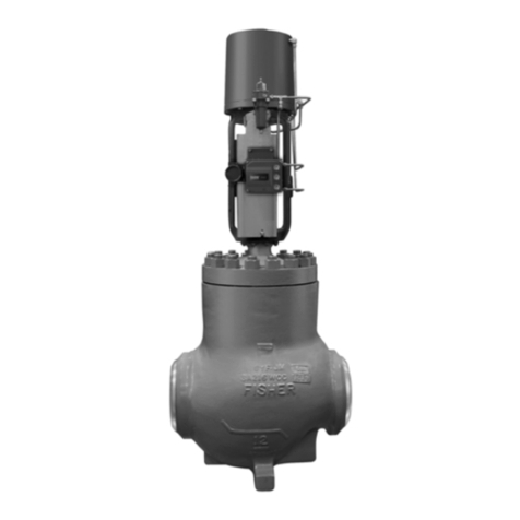
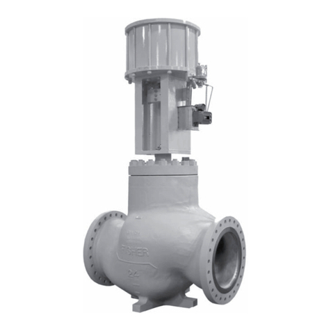
Figure 1. Fisher CV500 Valve
X0189
Fisher CV500 VALVE WITH 2052 ACTUATOR AND
FIELDVUE™DVC6200 DIGITAL VALVE CONTROLLER
Introduction
Scope of Manual
This instruction manual provides installation, operation, maintenance, and parts ordering information for NPS 3
through 12 Fisher CV500 Cam Vee‐Ball™rotary control valves. Refer to separate manuals for information concerning
the actuator and accessories.
Description
The CV500 Cam‐Vee‐Ball rotary control valve, has a Vee‐Ball style segmented ball in a valve body similar to the V500
valve. The CV500 is a flanged valve (figure 1) with a self‐centering seat, eccentrically rotating V‐notch ball, and splined
valve shaft. Suitable for forward or reverse flow use, this valve mates with a variety of actuators to provide throttling or
on‐off service. The flanged valve mates with ASME flanges or EN flanges.
Do not install, operate, or maintain a CV500 valve without being fully trained and qualified in valve, actuator, and
accessory installation, operation, and maintenance. To avoid personal injury or property damage, it is important to
carefully read, understand, and follow all the contents of this manual, including all safety cautions and warnings. If you
have any questions about these instructions, contact your Emerson sales office or Local Business Partner before
proceeding.
Instruction Manual
D101640X012
CV500 Valve
June 2017

