SEA USA User 1 24V DG R1B User manual
USER 1 - 24V DG R1B
24V ELECTRONIC CONTROL UNIT FOR SLIDING GATES AND BARRIERS
67411535 REV 10 - 02/2018
International registered trademark n. 2.777.971
SEA USA Inc.
10850 N.W. 21st unit 160 DORAL MIAMI
Florida (FL) 33172 USA
Tel. - :++1-305.594.1151 ++1-305.594.7325
Toll free: 800.689.4716
web site: www.sea-usa.com
e-mail: [email protected]

International registered trademark n. 2.777.971
IMPORTANT SAFETY INFORMATION
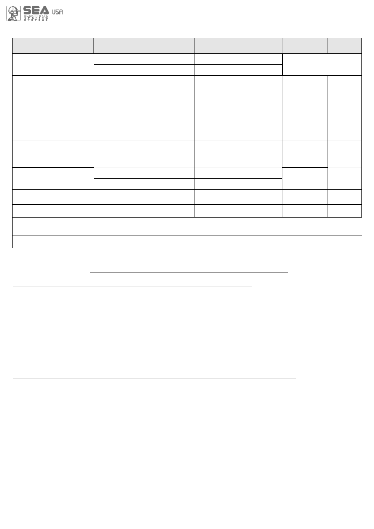
All the above described operations must be made exclusively by an authorized installer
Clean and grease parts in movement (wheels,
counter-connecting rod, release, etc.)
Check for corroded parts and replace if
necessary
Check if the screws and all mounting
hardwares are properly tighten
Annual
Annual
Annual
Check the conditions of wear and tear of the
devices in movement
Check the correct drain of the rainwater
Check the integrity of the connection cables
Annual
Annual
Annual
Inspect the track for any signs of cracking or
separation
Ensure that the gate moves freely
Annual
Annual
Check and confirm the proper operation of all
safety devices (photocells, edge sensors etc)
Check and confirm the operation of all
installed accessories
Check and confirm the operation of the
manual release
Annual
Annual
Annual
TURNING ON THE POWER
Check the battery conditions and be sure that
connections are free of corrosion
Verify the functionally of the battery backup,
or power failure option
BY MAIN POWER SOURCE TURNED OFF
Annual
TURNING OFF THE POWER
CCCC
GENERAL SAFETY PRECAUTIONS
The following precautions are an integral and essential part of the product and must be supplied to the user Read
them carefully as they contain important indications for the safe installation, use and maintenance.
1. These instruction must be kept and forwarded to all possible future users of the system.
2. This product must be used only for that which it has been expressly designed.
3. Any other use is to be considered improper and therefore dangerous.
4. The manufacturer cannot be held responsible for possible damage caused by improper, erroneous or
unreasonable use.
5. Avoid operating in the proximity of the hinges or moving mechanical parts.
6. Do not enter the path of the moving gate while in motion.
7. Do not obstruct the motion of the gate as this may cause a situation of danger.
8. Do not allow children to play or stay within the path of the moving gate.
9. Keep remote control or any other control devices out of the reach of children, in order to avoid possible involuntary
activation of the gate operator.
10. In case of break down or malfunctioning of the product, disconnect from the main power source.
Do not attempt to repair or intervene directly, contact only qualified personnel for repair.
11. Failure to comply with the above may create a situation of danger.
12. All cleaning, maintenance or repair work must be carried out by qualified personnel.
13. In order to guarantee that the system works efficiently and correctly it is important to have the manufacturer's
instructions on maintenance of the gate and operator carried out by qualified personnel.
14. In particular, regular checks are recommended in order to verify that the safety devices are operating correctly.
All installation, maintenance and repair work must be documented and made available to the user.
IMPORTANT SAFETY INSTRUCTIONS
WARNING – To reduce the risk of injury or death:
1. READ AND FOLLOW ALL INSTRUCTIONS.
2. Never let children operate or play with gate controls. Keep the remote control away from children.
3. Always keep people and objects away from the gate. NO ONE SHOULD CROSS THE PATH OF THE MOVING GATE.
4.Test the gate operator monthly. The gate MUST reverse on contact with a rigid object or stop when an object
activates the non-contact sensors. After adjusting the force or the limit of travel, retest the gate operator. Failure to
adjust and retest the gate operator properly can increase the risk of injury or death.
5. Use the emergency release only when the gate is not moving
6. KEEP GATES PROPERLY MAINTAINED. Read the owner’s manual. Have a qualified service person make
repairs to gate hardware.
7. The entrance is for vehicles only. Pedestrians must use separate entrance.
8. Every gate operator installation MUST have secondary protection devices agains entrapments, such as edge
sensors and photo beams more in particulary in places where the risk of entrapments is more likely to occur
9. SAVE THESE INSTRUCTIONS
!
PERIODICAL MAINTENANCE

GENERAL SAFETY INFORMATION
An appliance shall be provided with an instruction manual. The instruction manual shall give instructions for the
installation, operation, and user maintenance of the appliance.
The installation instructions shall specify the need for a grounding-type receptacle for connection to the supply and
shall stress the importance of proper grounding.
The installation instructions shall inform the installer that permanent wiring is to be employed as required by local
codes, and instructions for conversion to permanent wiring shall be supplied.
Information shall be supplied with a gate operator for:
a) The required installation and adjustment of all devices and systems to effect the primary and secondary protection
against entrapment (where included with the operator).
b) The intended connections for all devices and systems to effect the primary and secondary protection against
entrapment. The information shall be supplied in the instruction manual, wiring diagrams, separate instructions, or the
equivalent.
Vehicular gate operators (or systems)
A vehicular gate operator shall be provided with the information in the instruction manual that defines the different
vehicular gate operator Class categories and give examples of each usage. The manual shall also indicate the use for
which the particular unit is intended as defined in Glossary, Section 3. The installation instructions for vehicular gate
operators shall include information on the Types of gate for which the gate operator is intended.
A gate operator shall be provided with the specific instructions describing all user adjustments required for proper
operation of the gate. Detailed instructions shall be provided regarding user adjustment of any clutch or pressure relief
adjustments provided. The instructions shall also indicate the need for periodic checking and adjustment by a qualified
technician of the control mechanism for force, speed, and sensitivity.
Instructions for the installation, adjustment, and wiring of external controls and devices serving as required protection
against entrapment shall be provided with the operator when such controls are shipped with the operator.
Instructions regarding intended installation of the gate operator shall be supplied as part of the installation instructions
or as a separate document. The following instructions or the equivalent shall be supplied where applicable:
IMPORTANT INSTALLATION INSTRUCTIONS
a) Install the gate operator only when:
1) The operator is appropriate for the construction of the gate and the usage Class of the gate,
2) All openings of a horizontal slide gate are guarded or screened from the bottom of the gate to a minimum of 4 feet
(1.22 m) above the ground to prevent a 2-1/4 inch (57.2 mm) diameter sphere from passing through the openings
anywhere in the gate, and in that portion of the adjacent fence that the gate covers in the open position,
3) All exposed pinch points are eliminated or guarded, and
4) Guarding is supplied for exposed rollers.
b) The operator is intended for installation only on gates used for vehicles. Pedestrians must be supplied with a
separate access opening. The partial access opening shall be designed to promote pedestrian usage. Locate the gate
such that persons will not come in contact with the vehicular gate during the entire path of travel of the vehicular gate.
c) The gate must be installed in a location so that enough clearance is supplied between the gate and adjacent
structures when opening and closing to reduce the risk of entrapment. Swinging gates shall not open into public access
areas.
d) The gate must be properly installed and work freely in both directions prior to the installation of the gate operator. Do
not over-tighten the operator clutch or pressure relief valve to compensate for a damaged gate.
e) The gate operator controls must be placed so that the user has full view of the gate area when the gate is moving and
AWAY FROM THE GATE PATH PERIMETER.
f) Controls intended for user activation must be located at least six feet (6’) away from any moving part of the gate and
where the user is prevented from reaching over, under, around or through the gate to operate the controls. Outdoor or
easily accessible controls shall have a security feature to prevent unauthorized use.
g) The Stop and/or Reset button must be located in the line-of-sight of the gate. Activation of the reset control shall not
cause the operator to start.
h) A minimum of two (2) WARNING SIGNS shall be installed, one on each side of the gate where easily visible
International registered trademark n. 2.777.971

i) For gate operators utilizing a non-contact sensor:
1) See instructions on the placement of non-contact sensors for each Type of application
2) Care shall be exercised to reduce the risk of nuisance tripping, such as when a vehicle, trips the sensor while the
gate is still moving
3) One or more non-contact sensors shall be located where the risk of entrapment or obstruction exists, such as the
perimeter reachable by a moving gate or barrier
j) For a gate operator utilizing a contact sensor:
1) One or more contact sensors shall be located where the risk of entrapment or obstruction exists, such as at the
leading edge, trailing edge, and postmounted both inside and outside of a vehicular horizontal slide gate.
2) One or more contact sensors shall be located at the bottom edge of a vehicular vertical lift gate.
3) One or more contact sensors shall be located at the pinch point of a vehicular vertical pivot gate.
4) A hardwired contact sensor shall be located and its wiring arranged so that the communication between the
sensor and the gate operator is not subjected to mechanical damage.
5) A wireless contact sensor such as one that transmits radio frequency (RF) signals to the gate operator for
entrapment protection functions shall be located where the transmission of the signals are not obstructed or
impeded by building structures, natural landscaping or similar obstruction. A wireless contact sensor shall
function under the intended end-use conditions.
6) One or more contact sensors shall be located on the inside and outside leading edge of a swing gate. Additionally,
if the bottom edge of a swing gate is greater than 6 inches (152 mm) above the ground at any point in its arc of
travel, one or more contact sensors shall be located on the bottom edge.
7) One or more contact sensors shall be located at the bottom edge of a vertical barrier (arm).
Instruction regarding intended operation of the gate operator shall be provided as part of the user instructions or as a
separate document. The following instructions or the equivalent shall be provided
NOTICE
As for misunderstandings that may arise refer to your area distributor or call our help desk. These instructions are part
of the device and must be kept in a well known place. The installer shall follow the provided instructions thoroughly.
SEA products must only be used to automate doors, gates and wings. Any initiative taken without SEA USA Inc. explicit
authorization will preserve the manufacturer from whatsoever responsibility. The installer shall provide warning notices
on not assessable further risks. SEA USA Inc. in its relentless aim to improve the products, is allowed to make
whatsoever adjustment without giving notice. This doesn’t oblige SEA to up-grade the past production. SEA USA Inc.
can not be deemed responsible for any damage or accident caused by product breaking, being damages or accidents
due to a failure to comply with the instructions herein. The guarantee will be void and the manufacturer responsibility
will be nullified if SEA USA Inc. original spare parts are not being used. The electrical installation shall be carried out by
a professional technician who will release documentation as requested by the laws in force. Packaging materials such
as plastic bags, foam polystyrene, nails etc must be kept out of children’s reach as dangers may arise.
To respect the norms in force it is recommended to use the ENCODER SYSTEM together with the electronic
control units
International registered trademark n. 2.777.971
Starting on Jan. 12, 2016, new UL 325 changes take effect, bringing a series of new mandates for the gate operator
industry. Here’s a quick guide to the key modifications.
1. Entrapment-Protection Devices. Gate operators are required to have a minimum of two independent means of
entrapment protection where the risk of entrapment or obstruction exists. A manufacturer can use two inherent-type
systems, two external-type systems, or an inherent and an external system to meet the requirement. However, the
same type of device cannot be used for both means of protection.
2. Monitoring Required. An external non-contact sensor or contact sensor may be used as a means of entrapment
protection. However, the sensor must be monitored once every cycle for (1) the correct connection to the operator and
(2) the correct operation of the sensor.
If the device is not present, not functioning, or is shorted, then the gate operator can only be operated by constant
pressure on the control device. Portable wireless controls will not function in this case.
3. Entrapment Risk Identification. As in the past, it’s up to the installer to examine the installation and determine
where a risk of entrapment or obstruction exists. Manufacturers are required to provide instructions for the placement
of external devices, but they give only examples of suggested entrapment protection in their installation manuals. If the
installer identifies a risk of entrapment or obstruction, at least two independent means of entrapment protection are
required.
4.Terminology Change. The terms “primary” and “secondary” have been removed in the description of entrapment
protection devices. This was done to emphasize that all entrapment protection devices are equally important.
Changes to UL 325 ED. 6th for Gate Operators
5. The End of Type E. Type E (audible alarm) devices can no longer be used for entrapment protection. This change
was made because the Type E device is really a warning device, not an entrapment-protection device. Also, all gate
operator classes are now required to have an audio alarm that sounds when two successive obstructions are
encountered via a contact-type system.
6. Access Control Location for Emergency Use. An exception has been added in the manufacturer’s instructional
requirements for the location of controls that operate the gate.
The instructional requirements state that these controls must be at least 6' away from any moving part of the gate. In the
new exception, “Emergency access controls only accessible by authorized personnel (e.g., fire, police, EMS) may be
placed at any location in the line-of-sight of the gate.”
7. Barrier-Arm Operator Exception. An exception has changed for barrier-arm gate operators requiring entrapment
protection. The previous exception stated that a barrier-arm operator did not require entrapment protection if the arm
did not move toward a rigid object closer than 2'. The distance has been reduced to 16" so it more closely aligns with the
industry-defined entrapment protection provisions in ASTM F2200.
8. Gate Operator Class II and Class III Definitions. The definitions for installation classes for gate operators were
modified. Class II now includes commercial locations accessible to the general public. Class III was refined to specify
industrial locations not accessible to the general public. These changes, while seemingly minor, may affect which gate
operator is suitable for a particular installation location.
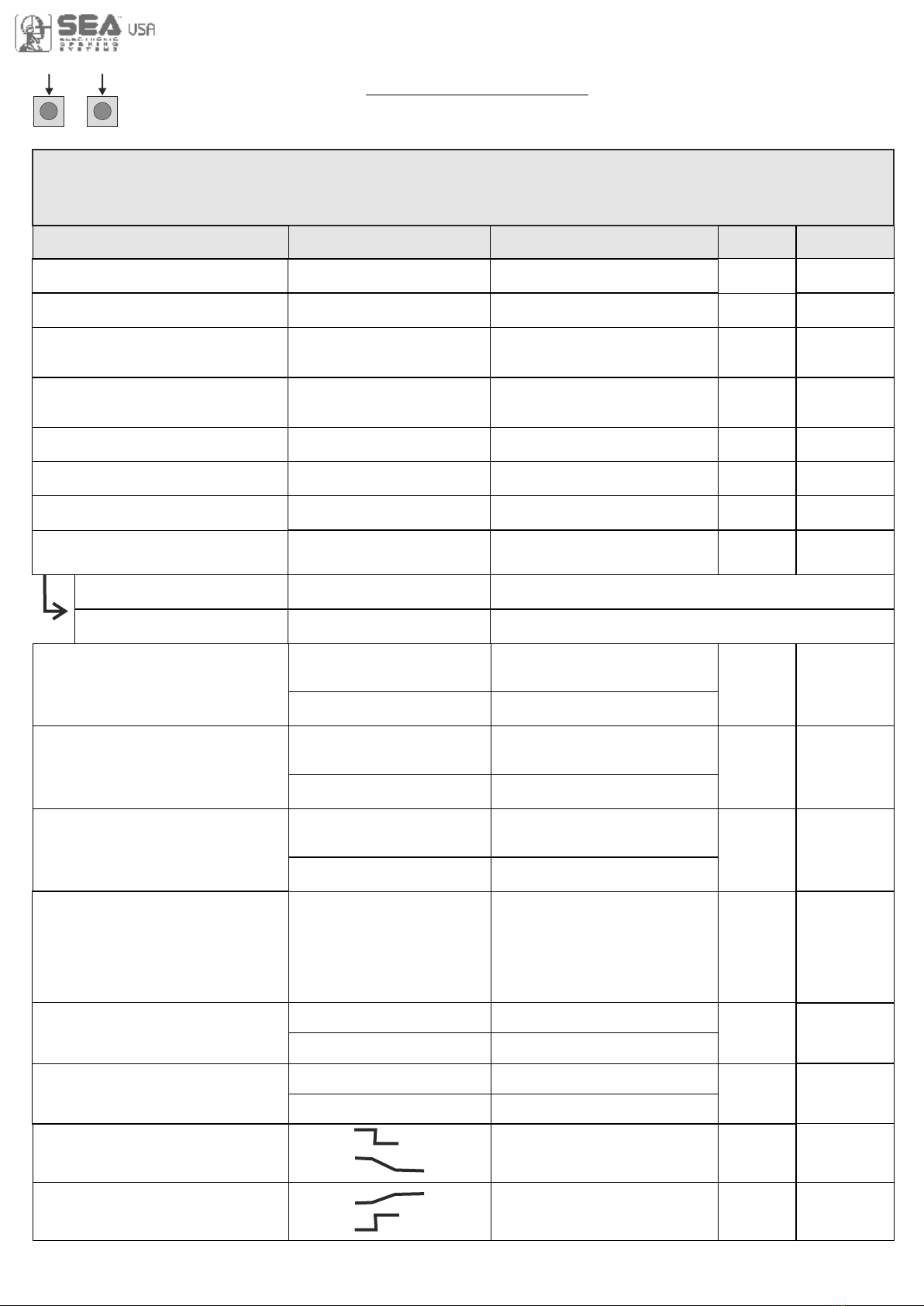
UL 325 ED. 6th ENTRAPMENT PROTECTION REQUIREMENTS
This vehicular gate operator must be installed with at least two independent entrapment protection
means as specified in the table below.
International registered trademark n. 2.777.971
VERITICAL BARRIER NOTE:
Barrier gate operators (arm) that is not intended to move toward a rigid objact closer than 16 inches (406mm)
are not required to be provided with a means of entrapment protection
* B1 and B2 means of entrapment protection MUST be MONITORED
HORIZONTAL SLIDE
VERTICAL LIFT - VERTICAL PIVOT
ENTRAPMENT
PROTECTION
TYPES
TYPE A
TYPE B1
TYPE B2
TYPE C
Inherent entrapment protection system
Non-contact sensors such as photoelectric sensors or equivalents
Contact sensors such as edge sensors or equivalent devices
Inherent force limiting, inherent adjustable clutch or inherent pressure relief device
The same type of device shall not be used for both entrapment protection means. Use of a single device to cover both
the opening and closing directions is in accordance with the requirement; however, a single device is not required to
cover both directions. Tice installer is required to install entrapment protection devices in each entrapment zone
TYPE D Actuating device requiring constant pressure to maintain opening or closing motion of the gate
SWING
VERTICAL BARRIER (ARM)
A , B1*, B2* or D A , B1*, B2*, C or D
GATE OPERATOR CATEGORY
Effective January, 12 2016
VEHICULAR GATE OPERATOR CLASSES
Residential Vehicular Gate Operator-Class I: A vehicular gate operator (or system) intended for use in garages or
parking areas associated with a residence of one-to-four single families
Commercial/General Access Vehicular Gate Operator-Class II: A vehicular gate operator (or system) intended for
use in a commercial location or building such as a multi-family housing unit (five or more single family units), hotel,
garages, retail store, or other buildings accessible by or servicing the general public
Industrial/Limited Access Vehicular Gate Operator–Class III: A vehicular gate operator (or system) intended for
use in an industrial location or building such as a factory or loading dock area or other locations not accessible by or
intended to service the general public
Restricted Access Vehicular Gate Operator–Class IV: A vehicular gate operator (or system) intended for use in an
industrial location or building such as a factory or loading dock area or other locations not accessible by or intended to
service the general public

6
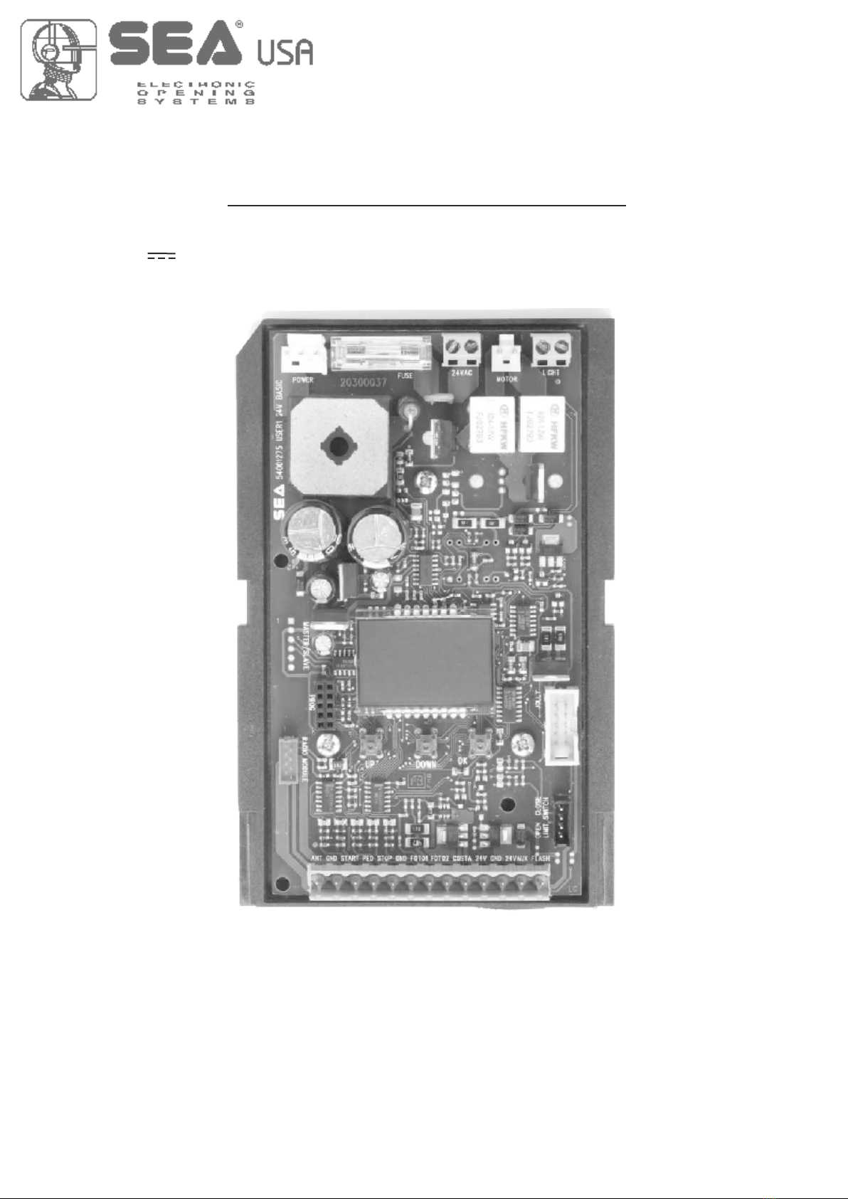
DESCRIPTION OF THE COMPONENTS
TECHNICAL SPECIFICATIONS
Control unit power supply: 24 V~
Absorption in stand by: 30 mA
Environment temperature: -20°C +50°C
Specifications of external enclosure: 305 x 225 x 125 mm - Ip55
JOLLY 3
CN8 F1
CN1
CNA
CN3
CN5
CNP
CN6
RL2
RL1
CN2
CN4
CN7
UP DOWN OK
RD3
RD1
PR1
DISPLAY
1 2 3 4 5 6 7 8 9 10 11 12 13
1
EXP
POWER FUSE BATTERY MOTOR LIGHT
MASTER/SLAVE
PROG
RADIO MODULE
JOLLY
LIMIT SWITCH
156 mm
100 mm
RICEVENTE RX
CNE
ENCODER
1COURTESY LIGHT
Cn1 = Input/Output connector
CN2 = Limit switch connector
CN3 = JOLLY 3 connector
CN4 = Master/slave connector
CN5 = Courtesy light output plug
CN6 = Motors connector
CN7 = Batteries connector - Quick connection
CN8 = Power connector
CNA = RX Receiver connector
CNE = Encoder connector
CNP = Programming connector
EXP = External module connector
OK = Programming button
DOWN = Programming button
UP = Programming button
RD1 =Motors piloting Mosfet
RD3 = Motors piloting Mosfet
R1 = Motors command relay
R2 = Motors command relay
PR1 = Rectifier jumper
F1 = Fuse 10 AT
7
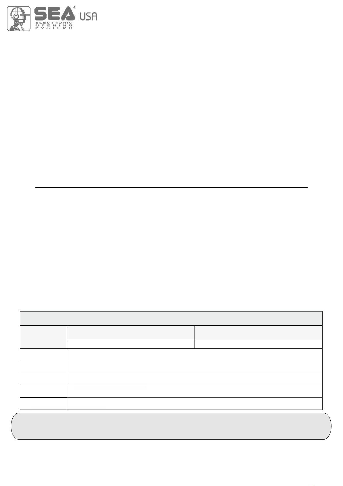
CONNECTIONS
The herein reported functions are available starting from revision 02.00 compatible with JOLLY 3
Start
Stop
Common
Antenna
START Ped.
Common
Photocell 1
Common
AUX
(24V 200 mA max)
24V 750 mA max
(Accessories)
Safety edge
Flash (-)
Photocell 2
WARNING: The control unit is designed with the automatic detection of not used N.C. inputs (photocells, Stop and Limit
switch) except the SAFETY EDGE input. The exclude inputs in self-programming can be restored in the “Check inputs”
menu without need to repeat the programming
Obligatory jumper
without
accessory connection
Limit switch Cl.1 (Yellow)
24V (Red)
Common (White)
Limit switch Op.1 (Green)
LIGHT (CN5)
Max 100mA
POWER (CN8)
24V~
MOTOR (CN6)
M
Max 200W
JUMPERS
123 4 5 6 7 8 910 11 12 13
CN1
ANT COM START
PEDST
STOP COM PH1 PH2
EDGE
AUX
COM 24V (FL)-
123 4 5 6 7 8 910 11 12 13
CN1
ANT COM START
PEDST
STOP COM PH1 PH2
EDGE
AUX
COM 24V (FL)-
Optional
+ +
- -
+ +
- -
LIMIT SWITCH (CN2)
1
ENCODER (CNE)
1
Brown
White
Green
Start
Stop
Common
Antenna
START Ped.
Common
Photocell 1
Common
AUX
(24V 200 mA max)
24V 750 mA max
(Accessories)
Safety edge
Flash (-)
Photocell 2
8
UP DOWN
5 s 5 s
UP DOWN OK
DISPLAY
1 2 3 4 5 6 7 8 9 10 11 12 13
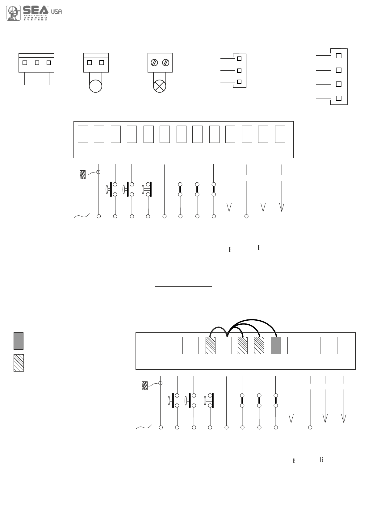
PROGRAMMING
FAST SELF-LEARNING
Start quick programming
You can start the quick programming by
holding UP for 5 s in the “Input check
menu", until the motor starts.
“Input check
menu"
Fast self-learning START command by
radio control
You can store the START button of the
remote control while pressing DOWN for 5 s
in the “Input check menu".
Once the writing "Press button" appears,
press the button of the transmitter, which
you want to store for the START command.
By pressing OK, you can exit the menu,
otherwise it will be left automatically after 5
seconds.

9
PROGRAMMING
BUTTONS
OK to exit
Menu or press
the button of
the next TX to
be stored
RECEIVER
MISSING
Skip this step if you do not want to program a transmitter
Choose the type of
motor with
UP or DOWN
To confirm and
return
to main menu
Choose "ON" with UP or
DOWN button only if in
programming the motor starts
in opening
With UP or DOWN
choose
the desired logic
With UP or DOWN
choose a delay for
automatic closing
With UP or DOWN
Choose ON
With UP or DOWN choose ON
to start times learning
At the end of the selflearning
the control unit returns automatically
to the main menu
With
UP or DOWN Choose
ON to start test
Skip this step if a TX has already been stored
ALL OTHER PARAMETERS HAVE DEFAULT SETTINGS WHICH ARE USEFUL FOR THE 90% OF THE APPLICATIONS
BUT CAN BE HOWEVER SET THROUGH THE SPECIAL MENU. FOR ENTERING INTO THE SPECIAL MENU MOVE
ON ONE OF THE MENU AND PRESS THE UP AND DOWN BUTTONS AT THE SAME TIME FOR 5 S
If on the display
appears the item:
Check if a receiver
has been connceted
The gate will execute a CLOSING-OPENING-CLOSING CYCLE
PROGRAMMING
QUICK START
MENU
SEA
SET
MENU
SEA
SET
MENU
SEA
SET
MENU
SEA
SET
MENU
SEA
SET
MENU
SEA
SET
MENU
SEA
SET
MENU
SEA
SET
MENU
SEA
SET
MENU
SEA
SET
OK
1
2
3
5
6
7
8
9
OK
OK
OK OK
OK OK
OK OK
OK OK
OK OK
UP
UP
UP
UP
UP
UP
UP
OKOK
START
MENU
SEA
SET
MENU
SEA
SET
MENU
SEA
SET
OK
UP
LANGUAGE ITALIANO
UP
MENU
SEA
SET
MENU
SEA
SET
OK
END
15
MENU
SEA
SET
OK
SPECIAL
MENU
16
UP
UP
10
OK
DOWNUP
OK
Go back to menu
9-PROGRAMMING,
replace the gate halfway
and repeat the timing
programming
TRANSMITTERS
MOTOR
REVERSE
MOTOR
LOGIC
PAUSE
TIME
START IN
PAUSE
PROGRAM-
MING
TEST
START
If the motor has
magnetic limit switches,
select "Magnetic"
in the special menu:
104 - SELECT LIMIT SWITCH
PRESS
BUTTON STORED
Skip this step
if you want to work
in half-automatic
logic
To confirm and
return
to main menu
To confirm and
return
to main menu
To confirm and
return
to main menu
To confirm and
return
to main menu
To confirm and return
to main menu
Press OK to return to the
display of the inputs state
Press OK to enter the special menu
Press the
button of the
TX to be
stored

10
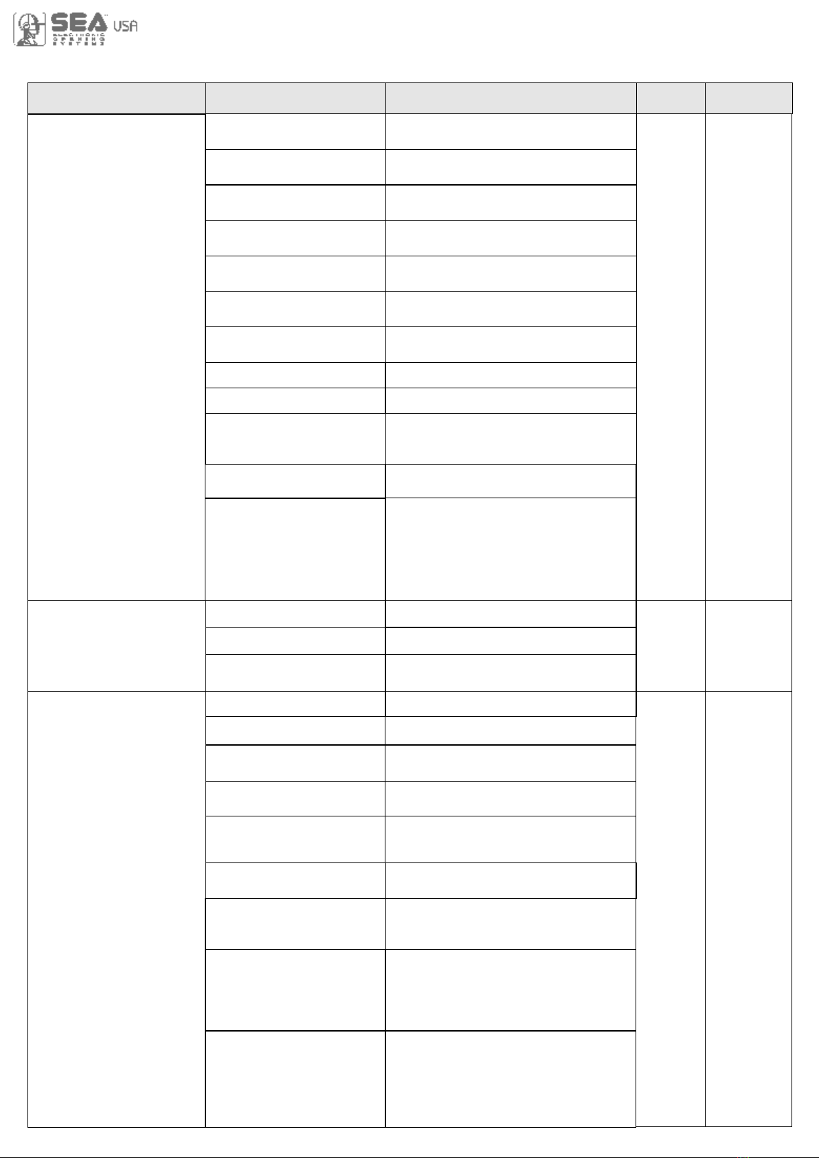
BASIC MENU
MENU SET
1 - LANGUAGE Español
English
Français
Italiano
Start
Dutch
Italiano
Stop
Unloch
External module
Partial opening Start
Clear memory
Delete a transmitter
End
2 - TRANSMITTERS
3 - MOTOR
MENU FUNCTIONS TABLE USER1 24V DG R1B
Start
Stop
Storing of a command
for unlocking an electric
brake
Italian
English
French
Spanish
External module
Partial opening Start
Delete single transmitter
Delete transmitter memory
Dutch
“Transmitters” menu output
Start
Partial
Opening
Start
Default
Description Set value
Sliding
Joint
Sprint 3 metres
Saturn
Mercury 800
VergL.5 metres
Erg Maxi
Erg
Verg
Sprint 4 metres
Sprint 5 metres
Storm 5 metres
Storm 6 metres
Storm 7,5 metres
VergL.4 metres
VergL.3 metres
Reversible sliding motors
Mercury Fast
Saturn 1500
Erg Maxi Double
Orion No LS
Taurus No LS
B-224 B-800 No LS
B-200 sliding and B-500
Joint
Sprint 3 metres
Saturn
Mercury 800
VergL.5 metres
Erg Maxi
Erg
Verg
Sprint 4 metres
Sprint 5 metres
Storm 5 metres
Storm 6 metres
Storm 7,5 metres
VergL.4 metres
VergL.3 metres
C-500 and Puma
Mercury Fast
Saturn Fast
Saturn Super Fast
Saturn 1500
Erg Maxi Double
Orion (without limit-switch)
Taurus (without limit-switch)
B-224 e B-800
(without limit-switch)
Saturn Fast
Saturn Super Fast
Sliding
Bistable Stop
Pressed once, it stops the
gate; pressed twice, it re-
active the Start command
11
WORKING TIMES SELF-LEARNING
1 240
Off Off
Off
On Off
Off
On
Off On
Off
Off
Off On Off
Automatic
2 buttons
Safety
Dead man
Open-stop-close-stop-open
Open-stop-close-open
Press OK to return to the display of the firmware version
and to the one of inputs state
Press OK to enter the special menu
8 - START IN PAUSE
6 - LOGIC
7 - PAUSE TIME
5 - REVERSE MOTOR
9 - PROGRAMMING
10 - TEST START
15 - END
16 - SPECIAL MENU
Synchronized right motor
Automatic
Step by step type 1
Step by step type 2
Two buttons
Safety
Dead man
Setting from 1s to 4min.
OFF
(semi-automatic logics)
In pause start is not acceped
In pause start is accepted
Start command
Times learning start
Synchronized left motor
Open-stop-
close-open
MENU SET
Default
Description Set value
WORKING TIME SELF-LEARNING ON MOTORS WITH LIMIT-SWITCH
PRELIMINARY NOTE: When using magnetic limit switches (such as on B-200 model), make sure that
the control unit is set on «magnetic limit switch» before learning:
MENU 104 - SELECT LIMIT SWITCH - “Magnetic”
1) Turn off the power supply, release the motor and place the door (or the barrier) manually at its mid run
2) Reset the mechanical lock
3) Select 9 - PROGRAMMING on the display, press OK and then one of the UP or DOWN buttons.
Now the gate will automatically execute a CLOSING-OPENING-CLOSING cycle
4) The self-learning is done
WORKING TIME SELF-LEARNING ON MOTORS WITHOUT LIMIT-SWITCH (NO LS)
PRELIMINARY NOTE: motors without limit-switch must have MECHANICAL STOPS IN OPENING AND
CLOSING set on the desired point of stop as in opening as in closing
Follow the points from 1 to 4 above shown as in the procedure for limit-switch motors
ATTENTION: If the motor starts in opening, remove and re-put power supply, select on the display
5-REVERSE MOTOR and through the UP and DOWN buttons select ON; if you have the Jolly3 programmer,
activate the motor exchange function and, only if present, limit-switch exchange function. If the motor starts
in closing and stops, remove the power supply and reverse the motor cables, then repeat the programming
procedure
ATTENTION: This procedure is potentially dangerous and should only be performed by qualified
personnel in safety conditions
The control unit is pre-set with DEFAULT settings. To start the control unit with the DEFAULT settings
just keep pressed the UP and DOWN buttons at the same time power supplying the control unit
till the display shows the message «INIT». The DEFAULT settings are shown in the Menues table

12
FUNCTION LOGIC
AUTOMATIC LOGIC
A start impulse opens the gate. A second impluse during the opening will not be accepted.
A start impulse during closing reverses the movement.
NOTE 1: To have the automatic closing it is necessary to set a pause time, otherwise all the logic will
be semi-automatic.
NOTE2: It is possible to choose, whether to accept or not, the start in pause, selecting in the MENU
the item 7-START IN PAUSE and choosing ON or OFF. By default, the parameter is OFF.
SECURITY LOGIC
A start impulse opens the gate. A second impulse during opening reverses the movement.
A start impulse during closing reverses the movement.
NOTE 1: To have the automatic closing it is necessary to set a pause time, otherwise all the logic will
be semi-automatic.
NOTE2: It is possible to choose, whether to accept or not, the start in pause, selecting in the MENU
the item 7-START IN PAUSE and choosing ON or OFF. By default, the parameter is OFF.
STEP BY STEP TYPE 1 LOGIC
The start impulse follows the OPEN-STOP-CLOSE-STOP-OPEN logic.
NOTE 1: To have the automatic closing it is necessary to set a pause time, otherwise all the logic will
be semi-automatic.
NOTE2: It is possible to choose, whether to accept or not, the start in pause, selecting in the MENU
the item 7-START IN PAUSE and choosing ON or OFF. By default, the parameter is OFF.
STEP BY STEP TYPE 2 LOGIC
The start impulse follows the OPEN-STOP-CLOSE -OPEN logic.
NOTE 1: To have the automatic closing it is necessary to set a pause time, otherwise all the logic will
be semi-automatic.
NOTE2: It is possible to choose, whether to accept or not, the start in pause, selecting in the MENU
the item 7-START IN PAUSE and choosing ON or OFF. By default, the parameter is OFF.
DEAD MAN LOGIC
The gate opens as long as the START button of opening is pressed; releasing it the gate stops. The gate
closes as long as the button connected to the PARTIAL OPENING START is pressed; releasing it the gate
stops. To execute complete opening and/or closing cycles the related pushbuttons must be constantly
pressed.
2 PUSHBUTTONS LOGIC
One start opens, one partial opening start closes. In opening the closing will not be accepted. In closing a
start command reopens, a partial opening start command (closes) will be ignored.
PASSWORD ENTERING MANAGEMENT
With a new control unit all menus can be displayed and set and the password will be disabled.
Selecting one of the Menus and keeping UP and DOWN pressed at the same time for 5 seconds, you will
access the SP Menu containing the 34-PASSWORD Menu. Pressing OK in the 34-PASSWORD Menu, you
will proceed with the entering of the numeric code of the 4-digit password. Use UP and DOWN to increase or
decrease the number, press OK to confirm it and you will pass automatically to the entering of the next
number. Pressing OK after the last entered number the word “Sure?” appears, confirm the activation of the
password and the message OK appears, pressing UP or DOWN instead you can cancel the operation and
“No operation” will appear on the display. Once entered the password, it will be definitively activated, once
the display switch off timeout has expired, or by turning off and on again the control unit. Once the password
has been activated, the menus of the display can be only displayed but not set. To unlock them you must
enter the correct password in the 34-PASSWORD menu, if the password is wrong the message “Error” will
appear. At this point, if the password has been entered correctly, the menus will be unlocked and it will be
possible to change the parameters of the control unit again. If the control unit has been unlocked through 34-
PASSWORD Menu, it is possible to enter a new and different password, using the same entering process as
for the first one; at this point, the old password will no longer be valid. If the password has been forgotten, the
only way to unlock the control unit is to contact the SEA technical assistance, which will assess whether to
provide the procedure to unlock the control unit or not.
Note: The password cannot be set through the Jolly 3 terminal.
13
UPDOWN
PRESS AT THE SAME TIME FOR 5 S TO ENTER OR TO EXIT THE SPECIAL MENU
SPECIAL MENU
MENU SP Default
SET
SPECIAL MENU FUNCTIONS TABLE USER 1 24V DG R1B
For entering into the special menu move on one of the menu and press the UP and DOWN
buttons at the same time for 5 s. For exiting the special menu press END or move on one of the
menu and press the UP and DOWN buttons at the same time for 5 s.
Description Set Value
30 100
30 100
30 100
30 100
30 100
10 100
10 100
10% (Fast intervention)
99% (Slow intervention)
Off (Intervention excluded)
10% (Fast intervention)
99% (Slow intervention)
Off (Intervention excluded)
- - - - -
Off
5 100
Off
5 100
17 - OPENING SPEED 1 *
18 - CLOSING SPEED 1 *
21 - OPENING SLOWDOWN
SPEED 1 *
22 - CLOSING SLOWDOWN
SPEED 1 *
25 - LEARNING SPEED *
28 - OPENING TORQ 1 *
29 - CLOSING TORQ 1 *
33 - OPENING SENSITIVITY
MOTOR1 *
34 - CLOSING SENSITIVITY
MOTOR1 *
57 - WORKING CURRENT
59 - OPENING
SLOWDOWN 1 *
60 - CLOSING
SLOWDOWN 1 *
10% (Fast intervention)
99% (Slow intervention)
Off (Intervention excluded)
37 - SLOWDOWN
SENSITIVITY
xxx.
xxx.
47 - ENCODER PAR.1 *
48 - ENCODER TOT.1 *
0 %
100%
63 - DECELERATION *
Setting from 30 to 100
Setting from 30 to 100
Setting from 30 to 100
Setting from 30 to 100
Setting from 30 to 100
Opening torq
Closing torq
Adjusts the intervention time
of the Encoder in opening
Disabled
Adjusts the intervention time
of the Encoder in closing
Disabled
Disabled
Adjusts the aperometric
sensitivity during slowdown
Shows the absorbed current
by the motor during the mo-
vement. The letter H at the
left of the current value indi-
cates the exceeding of the
set inversion threshold
Disabled
Setting from 5 to 100
Disabled
Setting from 5 to 100
Encoder impulses during operation
Encoder impulses stored
Adjusts the passage
between normal speed
and slowdown speed
30
30
* 50
* 50
* 80
* 80
* 40
* 40
* 50
* 60
* 60
30
On
32 - ENCODER
If ON it allows the
Encoder reading Off
0 %
100%
64 - ACCELERATION *
Acceleration ramp
Adjusts the motor start
Note: Menus 47 and 48 are present only if the encoder is ON
* 70%
* 50%

14
73 - CLOSING TOLERANCE
MOTOR1
0 100
82 - MOTOR RELEASE
1 100
Off
Disabled
Setting from 1 to 100
Off
Adjusts the tolerance
between stop and obstacle
closing
0
MENU SP Default
SET Description Set Value
0 15 6 %
0 15 6 %
70 - OPENING POSITION
RECOVERY
71 - CLOSING POSITION
RECOVERY
Retrieves the inertia of the
motor in opening after Stop
or reversing
Retrieves the inertia of the
motor in closing after Stop
or reversing
0 100
Adjust the tolerance between
stop and obstacle opening
72 - OPENING TOLERANCE
MOTOR1 0
Off
Off
79 - ANTI INTRUSION Only closing
Only opening
Opening and closing
If you force the gate
manually, the control
unit starts the motor to
restore the state of the
gate before forcing
85 - PREFLASHING
86 - FLASHING LIGHT
87 - FLASHING LIGHT
AND TIMER
88 - COURTESY LIGHT
89 - TRAFFIC LIGHT
RESERVATION
90 - PARTIAL OPENING
91 - PARTIAL OPENING
PAUSE
92 - TIMER
0.0 5.0
Only closing
Buzzer
Normal
Light
Always
Off
On
In cycle
1 240
Off
Off on
20 100
= Start
Off
Off
On photo2
On pedestrian entry
1 240
Pre-flashing only
active before closing
Pre-flashing time
Normal
Control lamp
Always ON
Buzzer
The flashing light remains
OFF with the active timer
and open gate
The flashing light remains
ON with active timer and
open gate
Disabled
Courtesy light setting
from 1s to 4 min
Courtesy light in cycle
Off
Normal
Off
Off
Off
30
= Start
Off
When setting this function
the partial opening input
will be activated to work on
the auxiliary board SEM
(traffic light management)
Setting from 20 to 100
Pause in partial opening
same as in total opening
Disabled
Setting from 1s to 4 min.
Transforms the selected
input in an input on
which to connect an
external clock
15
MENU SP Default
SET Description Set Value
Negative brake management
Negative Electrobrake
1 flash per sec. in opening
2 flashes per sec. in closing
Steady lit in Stop or Open
Gate open warning
light
Always AUX output always
power supplied
94 - 24V AUX
In cycle
In pause
Opening
Closing
AUX output power sup-
plied only during opening
AUX output power sup-
plied only during closing
AUX output power sup-
plied only during pause
AUX output active
only during cycle
Always
Fototest
In cycle and fototest
AUX output only during cycle
with fototest function active
AUX output for connection
of photocell TX to autotest
Positive brake management
Positive Electrobrake
95 - FOTOTEST
Photo1
Photo2
Photo1-2
Auto-test active only on Photo1
Auto-test active only on Photo2
Auto-test active on
Photo1 and Photo2
Photo1-2
97 - PHOTO1
Opening and closing
Closing
Stop and close
Close
Pause reload
Active in opening and closing
Photocell active in closing
The photocell gives a command
to close during opening, pause
and closing
The photocell charging
t h e p a us i n g t i m e
The photocell stops in closing
and closes when released
Closing
Delay pause time
If the photocell is occupied
during opening, pause or
closing, the gate reopens
completely and closes without
observing the pause time
Shadow loop
Until occupied with open gate,
it prevent reclosing. The loop
function is OFF during closing
Shadow loop RP
Until occupied with open gate,
it prevent reclosing. Once
released, the gate repeats the
pause timebefore closing.
The loop function is OFF during
closing
Stop
The photocell is active
also before opening
Start 3s
Barrier Led Light
the output will be activated at
each Start impulse for 3 seconds
The 24Vaux output will pilot the
lights on the barrier so that, with
the beam closed the light is on,
with the beam opened the light is
switched off and with the moving
beam the light is blinking

16
MENU SP Default
SET Description Set Value
98 - PHOTO2
Opening
Opening and closing
Closing
Stop and close
Close
Pause reload
Active in opening and closing
Photocell active in closing
The photocell gives a command
to close during opening, pause
and closing
The photocell charging
t h e p a us i n g t i m e
The photocell stops in closing
and closes when released
Delay pause time
If the photocell is occupied
during opening, pause or
closing, the gate reopens
completely and closes without
observing the pause time
Shadow loop
Until occupied with open gate,
it prevent reclosing. The loop
function is OFF during closing
Shadow loop RP
Until occupied with open gate,
it prevent reclosing. Once
released, the gate repeats the
pause timebefore closing.
The loop function is OFF during
closing
Stop
The photocell is active
also before opening
Stop N.O.
(only for VERG barrier)
It modifies the PHOTO2 input
into a Normally Open stop button
100 - EDGE1
8K2
Edge is active and pro-
tected by a 8K2 resistor
Normal
99 - PHOTO OFF
IN CLOSING 0 50 0
Setting from 0 to 50
Normal N.C. contact
Normal
8K2 Double
Photo 1 10K
Photo 1 10K Double
Allows to connect two
edges protected by a 8K2
resistor
Edge works as a photocell
protected by a 10K resistor
Allows to connect two
photocells protected by a
10K resistor
104 - SELECT
LIMIT SWITCH *
Mechanical limit switch
Magnetic limit switch
Mechanical
Magnetic
Mechanical
102 - EDGE
DIRECTION
Opening and closing
Only in Closing
Only in Opening
Active in opening and closing
Active only in Closing
Active only in Opening
Opening
and
closing
Stop and Open
If the photocell is activated during
opening, the gate stops and con-
tinues to open when released.
The photocell is ignored in
closure

17
1 10
Shows last event
(See alarms table)
106 - DIAGNOSTICS
0 240000 0
100 240000 100000
107 - MAINTENANCE
CYCLES
108 - PERFORMED
CYCLES
Setting from 100 to
240000
See Note 3 below
Reports the executed
cycles. Keep pressed
OK to reset the cycles
112 - PASSWORD - - - -
Allows the entering of a
password blocking the
control unit parameters
modification
- - - -
When ON, if no mains
power and batteries
connected, the gate
will open fully and will
remain open until the
power returns. At this
point it will perform an
automatic reclosing
113 - EMERGENCY Off On
Off
Press OK to exit the special menu.
The special menu switches off automatically after 20 minutes
120 - BASIC MENU
MENU SP Default
SET Description Set Value
From 30% to 100% 80%
119 - DISPLAY WRITING
SPEED
Note 1: The * indicates that the default value or the menu may change depending on the selected motor
type.
Note 2: After initialization the parameters "motor type" and "limit switch type" remain son the value chosen in
the setup program.
Note 3: Display writing speed set on 30% keeps writing slow; Display writing speed set on 100% keeps
writing fast. Please note that speed does not change on JOLLY 3 display.
105 - MASTER-SLAVE
Master
Slave
Off
Off
For applications with two
motors in master-slave,
you can set the control
unit as slave
For applications with two
motors in master-slave, it
allows to set the control
unit as master
Disabled
18
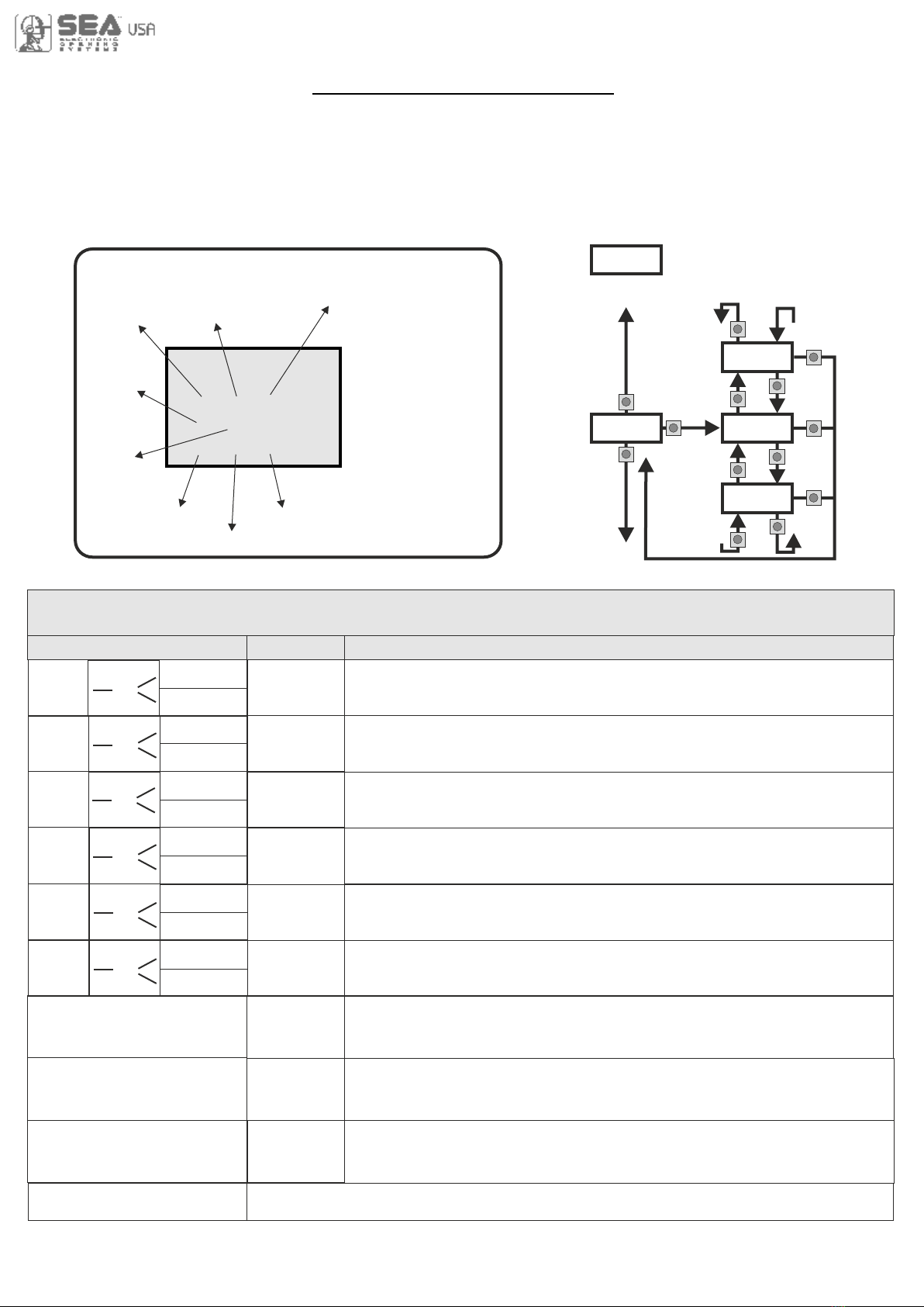
Initial system
Software Version
Programming example
DISPLAY INPUT STATUS
W h e n t h e
segment is ON
d u r i n g s e l f -
le arn in g, the
input status is
closed or OFF
Partial Opening
Start
Photocell 1
Photocell 2
Edge 1
MENU
SEA
SET
- - -
- -
- - -
Start
Stop
Limit
Switch
opening
motor 1
Limit
Switch
closing
motor 1
VERG
UP
OK
UP
UP
UP
DOWN
DOWN
DOWN
OK
OK
OK
DOWN
SCOR
JOINT
UP
U.001
MOTOR
LIMIT SWITCH
CLOSING
LIMIT SWITCH
OPENING
MENU
START
Description Description
EDGE
PHOTO1
PHOTO2
END
Start test
Safety edge
test
Photocell 1
test
Photocell 2
test
Opening
limit switch
test
Closing
limit switch
test
The contact must be a N.O. Contact . When activating the related
command on the display SET lights up, the input works.
If SET is always on, check the wirings.
The contact must be a N.C. Contact. When activating the related
command on the display SET lights up, the input works.
If SET is always on, make sure that the contact is a N.C. Contact
The contact must be a N.O. Contact. When activating the related
command on the display SET lights up, the input works.
If SET is always on, check the wirings.
The contact must be a N.C. Contact. When activating the related
command on the display SET lights up, the input works.
If SET is always on, make sure that the contact is a N.C. Contact
Ithe contact must be a N.C. Contact. When activating the related
command on the display SET lights up, the input works.
If SET is always on, make sure that the contact is a N.C. Contact
The contact must be a N.C. Contact. When activating the related
command on the display SET lights up, the input works.
If SET is always on, make sure that the contact is a N.C. Contact
Exit menu
OK
OK
MENU FUNCTION TABLE CHECK USER 1 24V DG R1B INPUTS
To access the Menu for input check keep pressed OK for about 5 seconds.
OK
0.0V
Batteries
Voltage
Level
Note: If the Stop, Photocell 1 and Photocell 2, Edge 1 contacts are not bridged in self-learning,
they will be deactivated and can be reactivated through this menu, without repeating times self-learning
The contact must be a N.C. Contact. When activating the related command on
the display SET lights up, the input works. If SET is always on, make sure that
the contact is a N.C. Contact. Menu active only on version with limit switches
Enabled
Enabled
Blocked
Blocked
Enabled
Blocked
Enabled
Blocked
Partial
opening
Start test
STOP OK
OK
START
PARTIAL
OPENING
OK
Enabled
Blocked
Enabled
Blocked
Stop test
Batteries charge level indicator
The contact must be a N.C. Contact. When activating the related command on
the display SET lights up, the input works. If SET is always on, make sure that
the contact is a N.C. Contact. Menu active only on version with limit switches
INPUT CHECK MENU
The settings of the control unit are made through the UP, DOWN and OK buttons. The UP and DOWN
buttons to scroll through the MENUS and SUBMENUS. By pressing OK you enter from MENU into
SUBMENU and confirm the choice. Moving in the 1-LANGUAGE menu pressing the UP and DOWN buttons
at the same time you access the SP MENU for special settings. Moving in the 1-LANGUAGE menu pressing
the OK button for 5 seconds, you enter the CHECK MENU, where you can check the operating status of all
inputs.

19
RADIO TRANSMITTER SELF LEARNING
WITH RECEIVER ON BOARD OF CONTROL UNIT
!
WARNING: Make the radio transmitters programming before you connect the antenna and insert
the receiver into the special CMR connector (if available) with turned off control unit. With RF UNI
and RF UNI PG module it will be possible to use both Coccinella Roll Plus transmitters and radio
transmitters with fixed code. The first memorized radio transmitter will determine the type of the
remaining radio transmitters. If the receiver is a Rolling Code, press twice the button of the radio
transmitter that you want to program to memorize the first TX. In the case of transmitters with fix code it is
necessary to press 1 time the button of the transmitter you want to program to store the first remote control
Notes:
- Enter radio transmitters learning only when the working cycle stops and the gate is closed.
- You can store max. 2 of the available 4 functions. If the control unit receives a code which was already
associated to another function it will be updated with the new function.
TABLE EXAMPLE
Transmitter
button
Memory
location
Serial
number Customer
MENU
SEA
SET
MENU
SEA
SET
MENU
SEA
SET
UP
MENU
SEA
SET
MENU
SEA
SET
MENU
SEA
SET
MENU
SEA
SET
UP
MENU
SEA
SET
MENU
SEA
SET
UP
MENU
SEA
SET
MENU
SEA
SET
MENU
SEA
SET
UP
MENU
SEA
SET
MENU
SEA
SET
UP
MENU
SEA
MENU
SEA
SET
MENU
SEA
SET
MENU
SEA
SET
SET
START
PARTIAL
OPENING
START
EXTERNAL
MODULE
STOP
DELETE A
TRANSMITTER
0OK? OK
CLEAR
MEMORY OK
PRESS
BUTTON STORED
STORED
STORED
STORED
PRESS
BUTTON
PRESS
BUTTON
PRESS
BUTTON
If you want to program the
partial opening start as
second channel
If you want to delete
a single transmitter
If you want to delete
the whole memory
If you want to program the
activation of the LIGHT
output as second channel
Press the
button of the
transmitter
to be stored
Press the
button of the
transmitter
to be stored
Press the
button of the
transmitter
to be stored
Select with
UP or DOWN
the memory
location
to be deleted
and press OK
Press the
button of the
transmitter
to be stored
If you do not want to execute the
cancellation, press UP or DOWN to
return to the 2-TRANSMITTER menu
Confirm the cancellation
If you want to program the
UNLOCH as second channel
MENU
SEA
SET
MENU
SEA
SET
UP
MENU
SEA
SET
UNLOCH STORED
PRESS
BUTTON
Press the
button of the
transmitter
to be stored
If you want to program the
STOP as second channel
OK
for 10 s.
MENU
SEA
SET
OK
TRANSMITTERS
OK
MENU
SEA
SET
If you want to exit the
2-TRANSMITTERS menu
END
MENU
SEA
SET
OK
UP
OK
OK
OK
OK
OK
OK
OK
Menu output
RF UNI 16 USERS Whitout memory
800 USERS With additional memory MEM
RF UNI PG 100 USERS Fixed code
800 USERS Roll Plus
RF UNI PG 800 UTENTI Fixed code
800 UTENTI Roll Plus
New model
Old Model
12 3 4
0
1
2
3
20
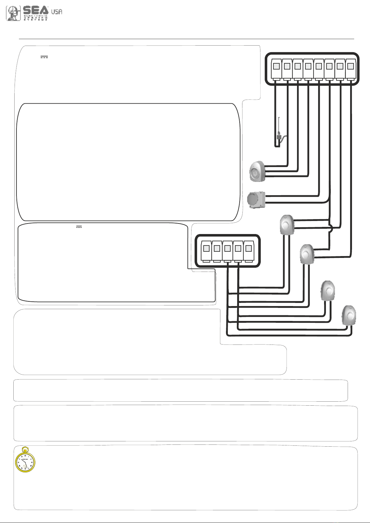
START - STOP - PARTIAL OPENING - ANTENNA - PHOTOCELL
START (N.O.) The START is connected between the clamps 2 and 3 of the CN 1 terminal.
An impulse given to this contact opens and closes the automation depending onthe selected logic it can be given by a key switch,
a keypad, etc. To connect the other devices refer to the related instructions leaflets. (ie. loop detectors and proximity switches).
Note1: In DEAD MAN logic it is necessary to keep pressed the Start for the opening of the automation.
Note2: In 2 BUTTONS logic this button performs the opening.
STOP (N.C.) The STOP is connected between the clamps 2 and 5 of the CN1 terminal .
The pressure on this button immediately stops the motor in any condition/position. A start command is needed to
re-start the movement. After a stop the motor always re-starts in closing.
Can be activated through on-board display or through the Jolly programmer. In both cases it’s a N.O. contact
which provoques the opening of the automation keeping it open until it is activated. When it’s released, the gate
attends the set pausing time and executes the reclosing. The TIMER command can be activated on the inputs
FOTO2, PARTIAL OPENING.
Note1: When activated on the pedestrian entry, the partial opening will be disabled also on the radio transmitter.
Note2: In case of intervention of a security device during the timer (Stop, Ammeter, Edge), to restore the movement it will be
necessary to give a start impulse.
Note3: In case of no power supply with open gate and active Timer the control unit will restore its use, otherwise if during restore
of the power supply the TIMER is not activated it will be necessary to give a start impulse for the reclosing.
TIMER
PARTIAL OPENING (N.O.) The partial opening can be connected
between the clamps 2 and 4 of the CN1 terminal .
This input allows a partial opening the opening space can be set through the
on-board display or through the JOLLY device.
Note1: The contact for partial opening is a N.O. Contact (Normally open).
Note2:In 2 BUTTONS logic it is necessary to keep pressed the Start Ped. to re-close the automation.
Note3: In dead man logic this button executes the re-closing if you keep it pressed.
Note4: When closed during pause, the gate will reclose only after this input has been reopened.
TIMER activation: This input can be transformed into TIMER (See TIMER).
Photocell 1 and Photocell 2 Connections
+ = 24V (Accessories) max 750mA COM = 0V PH1 = Photocell contact 1
PH2 = Photocell contact 2
Note: Self-test: connect the TX to the AUX clamp and activate the Autotest function. The
photocell 1 default setting is FOTO CLOSE and the photocell 2 one is FOTO OPEN. The
photocell 2 can be set also as TIMER (see TIMER function).
Note3: On the 26-FOTOTEST menu you can also activate the self-test even on the single
photocell.
OPTIONS ON FOTO1 and FOTO2 adjustable on on- board display or with
JOLLY terminal.
FOTO CLOSE activation (“Closing”): if occupied, reverses the movement in closing,
during pause it prevent the closing.
Activation repeat pause (“Pause reload”): If occupied, during pause it recharges the
timer of pause. In closing it reverses the movement.
FOTO OPEN AND CLOSE activation (“Opening and closing”): If activated the photocell
blocks the movement as long as it’s busy, when released the opening continues.
FOTO PARK activation (“Stop and close”) : in opening it is not active; in pause are
activated it commands the closing when released, otherwise it’s not active; in closing it stops
the movement as long as it is busy, when released the closing continues.
FOTO STOP activation (“Stop”): When activated before the opening the photocell blocks
the automation as long as it is busy, during the opening it will be ignored. In closing the
intervention of the photocell causes the reopening.
Activation PHOTO CLOSE IMMEDIATELY (“Close”): The photocell stops the gate as
long as it is occupied in both opening and closing, when released it gives a closing command
(Closing one second after release of the photocell ).
“Delay pause time”activation: If the photocell is occupied during opening, pause
or closing, the gate reopens completely and closes without observing the pause time.
Antenna
Common
Start
Start ped.
Stop
Common
Photocell 1
CN1
1 2 3 4 5 6 7 8
Photocell 2
RX1
RX2
TX1
TX2
CN1
9 10 11 12 13
Common
24V (Accessories)
Options AUX 24V max 200mA can be set with
on-board Display or with Jolly device.
Through the Jolly programmer it is possible to chose when
having tension on the AUX output. The options are: “Always”,
“In cycle”, “Opening”, “Closing”, “In pause”, “Fototest” and
“In cycle and fototest”. When using control units with batteries
and/or solar panels, we recommend connecting the accesso-
ries which are not used when operator stands still (e.g. photocells) to a
AUX output, setting the option “In cycle”. With this setting you can save
energy by lowering power consumption in stand-by, increasing the
autonomy of the system.
Table of contents
Other SEA USA Control Unit manuals

Popular Control Unit manuals by other brands

Gemu
Gemu 9650100Z 26T1-C Installation, Operating and Maintenance Instruction

Festo
Festo CPV-D102 Elektronics manual

ProMinent
ProMinent DHV-UR Assembly and operating instructions

Viessmann
Viessmann Vivotronic 050 HK1S Installation and service instructions

Flann Microwave
Flann Microwave 624 Instrument manual

Toshiba
Toshiba MD911 instruction manual


Danfoss
Danfoss Colibri ETS 12C installation guide

Circutor
Circutor line-EDS-PS instruction manual

MD
MD mXion APS user manual

Mitsubishi Electric
Mitsubishi Electric MELSEC iQ-R Series user manual

schmersal
schmersal SRB 320XV3 V.2 operating instructions

Resol
Resol EM Extension module Mounting, connection, operation