US USFF-300 User manual

Gas Vertical Type Fryer
Operating Instructions
Before you begin, please read these instructions carefully to use this product
correctly, to make the product perform ideally, and to avoid hazards.
Models: USFF-300 / USFF-400/ USFF-500

2
Dear customers and users:
Thank you for purchasing our product! In order to get the most out of this
product, please read these instructions carefully before operation. Follow the
guide, to avoid damage or injury.
Please keep this instruction manual for convenient reference and operation.
This instruction manual is subject to any change without further notice, and
the manufacturer reserves the right of final interpretation.
This appliance is designed for commercial purposes only, not for household use.
A statement instructing the purchaser to post in a prominent location
instructions to be followed in the event the user smells gas. This information shall
be obtained by consulting the local gas supplier.

3
Gas Vertical Type Fryer
The Installation, Operation and Maintenance Guide
Contents
Safety Protection ……………………………………………………4
Brief Introduction……………………………………………………4
Manufacturer's Authority and Responsibility ………………….…4
Parameter Specifications……………………………………………5-7
Transport and Storage ………………………………………………8
Installation and Debugging…………………………………………8-9
Safety Notices and Precautions……………………………………10
Operating Instructions……………………………………………11-12
Cleaning and Maintenance…………………………….…..……12-13
Service ………………………………………….…………….…14-16
Troubleshooting …………………………………………………17-18
Spare Parts ………………………………………………………19-23
Accessories List……………………………………………………23

4
Safety Protection
Ensure that the operator is an authorized and licensed technician before allowing
him/her to install and operate the product. Be sure to strictly follow this instruction
guide during installation and using. The manufacturer is not responsible for any
danger or accidents caused by improper operation or maintenance.
Do not store flammable or explosive objects around the product. Keep all flammable
and explosive objects at a safe distance away from the product for normal use.
Place the product in a reasonable position. Regarding related matters of gas,
customer should execute the requirements of local gas supply sector.
If you smell a gas leak, turn off the gas valves immediately and call the gas
company.
The product should only be operated by experienced persons over the age of 18, in
good mental and physical health.
Brief Introduction
This product is a series of gas fryers in our company production. Which is quality
designed, reasonably structured, conveniently operated, durable, and conveniently
maintained. Equipped with a high efficiency cast-iron burner and pilot light to ignite the
main fire burner. This is hotel, supermarket, western restaurant, and food industry's ideal
fryer product equipment.
Manufacturer's Authority and Responsibility
Banning of all or partial transformation to the products without the manufacturer's
explicit authorization.
Manufacturers refuse to undertake responsibility to third parties as the following
reasons:
Not following this instruction and warning in using and testing;
Not in accordance with the requirements of technical parameters using this product;
Incorrectly or irrationally using the product by untrained personnel;
Not obeying the local law using this product;
Repairs or changes made by unauthorized technicians;
Use the spare parts or accessories provided by non-manufacturers;
Accidents caused by forces of nature;
Not strictly complying with related guide of instruction by any reason.

5
Parameter Specifications
Outline Dimensions (inch)*
USFF-300/USFF-400

6
USFF-500

7
Information of Gas Supply and Burner
The minimum supplied gas pressure regulator is factory set at 4”Natural Gas W.C,
and 10”L.P. Gas W.C. The external thread of product’s intake-tube is 3/4 inches
Table 1
Model
#of burners
and control
method
Gas
Species
Intake-tube
pressure
(in W.C.)
Per BTU
B.T.U./h
Total BTU
B.T.U./h
Nozzle
No.
USFF-
300
3 pieces
Integrated
control
Natural
Gas
4
34,000
102,000
#36
L.P. Gas
10
30,000
90,000
#52
USFF-
400
4 pieces
Integrated
control
Natural
Gas
4
34,000
136,000
#36
L.P. Gas
10
30,000
120,000
#52
USFF-
500
5 pieces
Integrated
control
Natural
Gas
4
34,000
170,000
#36
L.P. Gas
10
30,000
150,000
#52

8
Transport and Storage
During transportation, handle carefully and keep upright to prevent damage of the
product packing. Wrapped equipment should not be in open air for a long period of time,
and shall be placed in a well-ventilated and non-corrosive gases warehouse. When
equipment needs temporary storage, rainproof measures should be taken.
Installation and Debugging
Any erroneous installation, adjustment, refit, overhaul or maintenance may cause
property damage or personal injury. The work shall be performed by authorized and
licensed technicians, otherwise the manufacturer has the right to void warranty
service;
Must be installed in accordance with the local code. If no similar standard, you
should conform to the National Fuel Gas Code, ANSI Z223.1/NFPA 54, the National
Gas Installation Code, CSA-B149.1, or the L.P. Gas Installation Code, CSA-B149.2
as applicable;
The appliance shutoff valve must be disconnected from the gas supply piping
system during any pressure testing of that system at test pressures in excess of
1/2psi (3.45kPa).
Unpacking and Installation
Please dispose of all packaging materials and residues after unpacking;
Check the equipment. If it is damaged, please keep packing materials and receipts
signed by the carrier representative (Driver), and contact the carrier to file a claim
within 15 days after receiving;
Check all accessories complete. Refer to P18 table 4;
Install supporting legs before using, and do not damage any label or logo before use;
Please read these instructions carefully before installation and operation. Contact
your local agent if you have any questions;
The equipment is to be installed on a level, solid, non-skid and incombustible
surface, and placed in a well-lit waterproof work area; away from children and
customers;
The installation position must be well-ventilated in accordance with local regulations;

9
Equipment must be installed under the matched cooking fume exhauster according
to local regulations;
Important: Installation and ventilation laws, and codes are very different, should state
and comply with all codes of the National Fire Protection Association Inc. when it
comes to requirements for installation of equipment;
Unscrew the matched 4 nuts, slip over steel legs, then screw nuts, see Fig.1;
Adjustable stainless steel legs to make the equipment level, and get the same level
with other series of the same stove; Please lift the equipment rather than drag if
needs moved;
Slipped over internal upper smokestack, screw it with a self-tapping screw; Slipped
over external upper smokestack, screw it with a self-tapping screw; Specific
installation steps and methods see Fig.2, Fig.3 for reference;
Keep a distance of at least 6 inches(152mm) to equipment’s sides and back, and
keep distance of at least 4 inches(102mm) to the bottom;
Do not put anything around the equipment, and on the counter top and bottom, in
order to avoid influencing combustion and air circulation;
Thread glue must be resistant to the action of liquefied petroleum gases.
Warning! Use soap and water or testing instrument to test whether piping joint leaks
or not before using, and forbid using an open flame to test!
Fig.1 Fig.2 Fig.3
Debugging
It’s very important to debug the new stove. Through the comprehensive system test
of equipment, we can ensure function and safety performance of products. Discovering
any potential problems before use (such as equipment’s placement, ventilation,
operation, etc), can avoid costly losses.

10
Safety Notices and Precautions
Warning! For your safety, do not place petrol and other flammables nearby. Please
keep clean and free of flammables surrounding. (Read ANSI Z83.14B, 1991 for
reference)
Warning! Any erroneous installation, adjustment and refit may cause property
damage or personal injury and maintenance failure. Read the instructions carefully
before installation and using.
Warning! Operation instruction must be placed in a conspicuous location. When
customers smell gas in the process of using, take safety precautions immediately.
Immediately turn off the main gas valve, extinguish all heat and flames, and call 911.
Safety information can be obtained from your local gas suppliers.
When using this equipment, safety precautions should always be
followed, including the following:
Do not touch high-temperature smokestack plate to prevent burns when in using or
just after using;
Do not cover exhaust port with anything when in using to affect the combustion
effect, even cause severe accidents;
Turn off the equipment as not in use or no operator here;
Turn off the equipment while repairing, maintaining or cleaning;
If the equipment has any problems of equipment damage, gas piping leaks, igniter or
valves damage, or lose product accessories, do not operate and call for service
immediately;
The use of attachments not recommended or sold by the manufacturer may cause
fire, personal injury or even death;
Do not use outdoors;
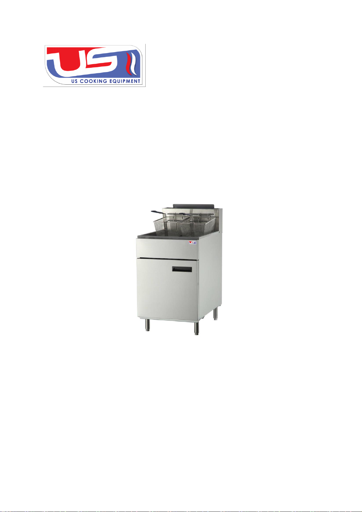
The equipment is used for frying, not for any other use;
The equipment does not contain any user-serviceable parts. Dealers or technicians
will repair it. Do not take apart any spare parts without authorization;
Never change any other parts without authorization to this equipment. Otherwise,
may cause hazards, and the manufacturer has the right to void warranty service;
Steel cutting producers used to manufacture with sharp edges. The manufacturer
has dealt with these sharp edges during production, however, we insist the operator
take care when in contact with this piece of equipment;
Always keep hands, hair and clothing away from heating source.
Always allow unit to cool down before cleaning.

11
Operating Instructions
Before operating, make sure to place the unit horizontally by adjusting bottom
adjustable legs.
Lighting the pilot light
●Ensure thermostat is “OFF”before lighting;
●Turn safety valve knob to “PILOT”(Fig.4), press down by force and do not loosen, light
the pilot (Fig.5), press and hold knob for 30-45 seconds; loosen knob if pilot is lighting,
otherwise relight and press knob continually;
●When pilot light burns continually, turn knob to “ON”(Fig.6), without pressing knob.
Fig.4 Fig.5 Fig.6
Igniting the main burner
●After lighting the pilot light, turn on the main valve by turning temperature control knob
clockwise, ignite the main burner by the pilot light, turn temperature control knob to
proper temperature according to user demand;
Ensure there are liquid edible oil or solid shortening in hydro-cylinder before lighting
the main fire;
Do not over the oil level line;
Do not ignite the main fire without any oil in hydro-cylinder to prevent damage to
equipment or severe injury;
Turning off the valve
●Turn temperature control knob to “OFF”, extinguish the flame of the main fire burner;
●Turn safety valve knob to “PILOT”, this is in a standby state, the pilot light is burning;
●Press down safety valve and turn to “OFF”.

12
Cooking
●Before using the equipment for the first time, use a mild detergent to wipe down for
cleaning. Do not use corrosive or abrasive detergents.
●Pour liquid edible oil or solid shortening into hydro-cylinder, and do not fill over the oil
level line;
●If there is shortening, change to the lowest temperature to prevent burning and
charring;
●Once temperature reaches the preset temperature place fryer basket in place.
●If the smell of oil changes during the process of frying due to too high temperature or
too many impurities in the oil. Change or filter oil to resolve;
Install the matched cooking fume exhauster according to the local regulations of the
char broiler;
Make sure to keep the air natural circulation in the kitchen.
Note: Each burner nozzle has been installed before delivery, normal use without
change but only switching gas.
Cleaning and Maintenance
This product is made with high quality stainless steel material, and should be maintained
carefully. Clean frequently to ensure better performance. Cleaning frequency depends on the
use intensity. Climate factors must also be taken into consideration. Daily maintenance can
improve the life of the boiler.
●Instructions to clean appliance regularly with recommended cleaning agents, if
necessary.
●Clean the inner part of the hydro-cylinder, fryer basket, grid and drain oil pipe:
1. Pour moderate water and detergent into hydro-cylinder (Do not fill over the highest
height of the oil level line)
2. After mix fully, turn on the main fire burner heating, turn off the main fire burner after
heating about 5-10 minutes;
3. Soak the hydro-cylinder, fryer basket and drain oil pipe in the solution for a period of
time;
4. When water temperature cools down to suitable body temperature, wipe the hydro-
cylinder inner wall and combustion tube surface with cleaning cloth, Use cleaning cloth on
the fryer basket, grid and drain oil pipe. Do not use, wire brush or a hard object to wipe
surface of the hydro-cylinder, wipe along the direction of metal original polishing lines;
5. Turn on oil drain valve to empty slopes.
6. Rinse hydro-cylinder with clean water.

13
●Clean the equipment surface:
Wipe clean dust, grease and residue on the surface of equipment with clean and mixed
detergent cloth. Dry with a clean cloth; do not use vinegar or corrosive liquid.
Do not use any abrasive or flammable detergent to wipe;
Do not hose down, immerse or pressure wash any part of the cooker;
Do not use abrasive cleaning matters to wash, even not use corrosive detergent!
●Inner smokestack cleaning/maintenance: after use 3-6 months or when necessary must
clean/maintenance smokestack by the manufacturer, service agent or a similarly qualified
person in order to avoid a hazard.
Warning: Before cleaning, all control valves must be turned off. Strictly follow the
lighting instructions to work again after cleaning!
Warning: Wait for the equipment to cool down after the unit has been turned off
before you clean!
Cut off the gas source as not using;
If the equipment is not used for a long time, clean the surface by wiping it with a soft
cloth and place it in a well-ventilated area;
Comprehensively check the equipment at least once every year by authorized and
licensed technicians;
The product is made of 90% metals, and cannot be discarded everywhere. Check to
be in accordance with the local codes.

14
Service (authorized technicians only)
All equipment has been debugged before delivery. If have the following problems, such
as initial installation, gas or piping pressure issues, please refer to the relevant information
on the equipment label or instructions.
Check and adjust the main burner.
There will be stable blue flame on the normal main burner; each flame port is 3/4 inches
long.
Yellow flame (lack of air) Blow flame (too much air) Normal flame
Check and adjust pressure regulator.
Supplied gas pressure regulator is factory set at 4”Natural
Gas W.C, and L.P. Gas pressure is factory set at
10”Natural Gas W.C;
Use a pressure gauge which is equipped with liquid (such
as U-type pressure gauge, the minimum value is 0.1mbar)
or a digital pressure gauge to test.
Steps are as follows; Reference picture to right.
1. Open cabinet door, remove needle type pressure joint screw arbor, slip
rubber tube of pressure gauge over needle type pressure joint;
2. Start the equipment in accordance with the instructions, measuring gas
supply pressure (dynamic pressure) in the work state;
3. Access to the equipment if measured data within the limits of Table 1, otherwise, you will need to adjust
gas pressure regulating valve or contact gas supplier.
4. Unplug pressure gauge after you accomplish pressure testing, then install needle type pressure joint
screw arbor.
Important: must screw joint arbor in order to avoid gas escaping!

15
●Check and adjust thermostat calibration;
All thermostats have been debugged before delivery; such as properly debugged a variety of
detailed parameters. Debugging by authorized off-sale service technicians only.
1. Test equipment temperature with thermometer; place thermocouple in middle of boiler.
2. Adjust control details in place, read number when temperature stabilizes.
3. If the set temperature and measurement temperature difference at 10 degrees Fahrenheit,
Check temperature again.
4. Delete number on the “B”, make sure reading drive is the initial state.
5. Keep “B”stable; adjust “A”by a bolt driver clockwise, dropping in temperature, or
increasing temperature counter-clockwise.
6. Reset dial scale, measure temperature, confirm temperature whether adjusted completely.
7. If modified successfully, please recover sealing screw.
Connection Diagram

16
●Check and adjust automatic safety controller;
The flame should surround thermoelectric couple 1/2 inches, the fire must be large
enough to keep the thermocouple being red, or cannot keep the safety valve open.
1. Remove controller copper adjusting cap.
2. Adjust controller knob, ensure appropriate flame (B). A is incorrect set.
3. Reset adjusting cap.

17
Troubleshooting
Table 2
Problem
Cause
Resolution
Not lighting
1.Insufficient gas
pressure in pipe
1.Contact the
local gas supply
dept.
2.Nozzle occlusion
2.Dredge nozzle
Ignite the pilot
light but not the
main fire
1.Insufficient gas
pressure in pipe
1.Contact the
local gas supply
dept.
2.The main fire
nozzle occlusion
2.Dredge nozzle
3.Gas control valves
have problems
3.Change gas
control valves
4.The pilot light and the
main fire’s distance is too far
4.Adjust the
distance of them
5.Flame is too low
5.Adjust the
height of the pilot
light
Close gas and
heard a sound
of fire
1.Insufficient gas
pressure in pipe
1.Contact the
local gas supply
dept.
2.Not match nozzle aperture
with gas resources
2.Adjust nozzle
diameter
3.Flow of connection
pipe is not enough
3.Increase pipe’s
allowable flow

18
4.Damper opening
degree is too large
4.Adjust damper
Yellow flame
and black
smoke
1.Use bottom gas
1.Change gas
2.Not match nozzle aperture
with gas resources
2.Adjust nozzle
diameter
3.Not enough air to ignite
3.Increase
damper opening
degree
4.In the peak of
using gas, sources
of gas float heavy
4.Turn down
valves flow. Turn
it up after the
peak
Table 2 Cont.
The problems mentioned above are only for reference. If any fault occurs, please
stop using, and contact technicians to check and repair. Turn off the power and gas
supply before maintenance.

19
12. Spare Parts
The use of parts provided by other companies, our company has the right not
to provide warranty service;
Order replacement parts from authorized representatives and after-sale
service agency.
Provide the model no., serial no. and description when you order
components.
Fig 8.

20
Table 3
No.
Matters
Code
Component
name
Qty
Dimensions
(mm)/Model
Remark
1
21201001001
Body assembly
1
394*746*751
USFF-
300\400
21201003001
534*746*751
USFF-500
2
301060017
Lower axillare
assembly
1
USFF-
300\400\500
3
21201001007
Door assembly
1
392*34*529
USFF-
300\400
21201003007
532*34*529
USFF-500
4
301060016
Upper axillare
assembly
USFF-
300\400\500
5
21101001032
Front panel
1
USFF-
300\400
21101003032
USFF-500
6
301050001
oil drain valve
1
USFF-
300\400\500
7
301030006/30
1990002
Thermocouple/
Ignition bracket
1
21424/66932
USFF-
300\400\500
8
301010005
Burner
3
USFF-300
4
USFF-400
5
USFF-500
This manual suits for next models
2
Table of contents
Popular Fryer manuals by other brands

Tidylife
Tidylife AF-11A-2 Operating and safety instructions

ARIETE
ARIETE AIRY FRYER DIGITAL manual

LANOX
LANOX LA-605A operating manual

MIGEL
MIGEL GAF 140 manual

GIGA
GIGA IFTE1 Installation, Operating and Maintenance Instructions for the Installer and the User

Vollrath
Vollrath Cayenne FFA7110 Operator's manual