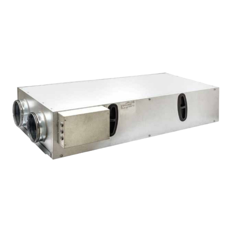
UTEK REVERSUS Quick start guide

REVERSUS
indoor air quality and energy saving
MANUALE DI INSTALLAZIONE, USO E MANUTENZIONE
GUIDE FOR INSTALLATION, USE AND MAINTENANCE
UNITÀ DI VENTILAZIONE con RECUPERO DI CALORE per EDIFICI RESIDENZIALI
HEAT RECOVERY VENTILATION UNITS for RESIDENTIAL BUILDINGS

Dear Customer
Thanks for your attention to the product UTEK , designed
and manufactured to ensure the real values to the User:
Quality, Safety and Savings on working.
Gentile Cliente
Grazie per l’attenzione al prodotto UTEK, progettato
e realizzato per garantire all’Utilizzatore valori reali:
Qualità, Sicurezza e Risparmio sui consumi.
pag.3
pag.3
pag.3
pag.4
pag.4
pag.4
pag.5
pag.6
pag.7
pag.7
pag.8
pag.10
pag.12
pag.12
pag.15
pag.15
pag.15
pag.15
pag.16
pag.18
pag.18
pag.3
pag.3
pag.3
pag.4
pag.4
pag.4
pag.5
pag.6
pag.7
pag.7
pag.8
pag.10
pag.12
pag.12
pag.15
pag.15
pag.15
pag.15
pag.17
pag.18
pag.18
INDICE
NORME DI SICUREZZA E MARCHIATURA CE
RISCHI RESIDUI
RICEVIMENTO DELLA MERCE
MOVIMENTAZIONE
IMMAGAZZINAMENTO
CONDIZIONI DI INSTALLAZIONE
INSTALLAZIONE A PAVIMENTO
INSTALLAZIONE A PARETE
NORME DI MANUTENZIONE
CONFIGURAZIONI
MANUTENZIONE E PULIZIA FILTRI E SCAMBIATORE
ISTRUZIONI MONTAGGIO PANNELLO REMOTO
MONTAGGIO SCARICO CONDENSA
ACCESSORI
COLLEGAMENTI ELETTRICI
MESSA IN SERVIZIO
PROCEDURE DI ACCENSIONE
FERMO PROLUNGATO
ANOMALIE DI FUNZIONAMENTO
MONTAGGIO E SMONTAGGIO
SMALTIMENTO
INDEX
SAFETY STANDARDS AND CE MARKING
RESIDUAL RISKS
RECEIPT OF GOODS
HANDLING
STORAGE
CONDITIONS OF INSTALLATION
FLOOR INSTALLATION
WALL INSTALLATION
MAINTENANCE RULES
CONFIGURATION
MAINTENANCE AND CLEANING FILTERS AND EXCHANGER
REMOTE PANEL ASSEMBLY INSTRUCTIONS
CONDENSATE DRAIN ASSEMBLY
ACCESSORIES
ELECTRICAL CONNECTIONS
COMMISSIONING
IGNITION PROCEDURES
LONG STOP
OPERATING FAULTS
ASSEMBLY AND DISASSEMBLY
DISPOSAL

3
SAFETY STANDARDS AND “CE” MARKING
The CE marking and the relevant declaration of conformity prove
the conformity to the applicable community regulations. CLA s.r.l.
are exemp-ted from any responsibility attributable to damage
caused to persons and things resulting from the non-compliance
with the safety standards and any product modifications.
REMAINING RISKS
The unit, before being switched on, must be ducting.
DPI
GOODS RECEPTION
Each product is carefully checked before shipping. On goods
reception, it is necessary to make sure that products have not
suffered any damages during transport. Each unit is placed inside
a special box, which is then placed on a custom-made pallet and
fixed to it by means of straps. A protective film covers the entire
package.
The unit label is always visible on the packaging and contains the
following information:
- Manufacturer's address and CE marking
- unit code, serial number and order number
- descriptive
- information on fans and flow rate
On the box there is always a transparent envelope containing the
installation, use and maintenance manual and the wiring
diagram.
NORME DI SICUREZZA E MARCHIATURA “CE”
Il contrassegno CE e la relativa dichiarazione di conformità
attestano la conformità alle norme comunitarie applicabili. CLA
S.r.l. si esime da ogni responsabilità per eventuali danni causati
a persone e cose derivanti dalla mancata osservanza delle
norme di sicurezza, nonché dalle eventuali modifiche apporta-
te al prodotto.
RISCHI RESIDUI
L’unità, prima di essere accesa, deve essere canalizzata.
Leggere attentamente il seguente manuale prima
di
effettuare qualsiasi azione sulla macchina
DPI
RICEVIMENTO DELLA MERCE
Ogni prodotto viene controllato accuratamente prima di
essere spedito. All’atto del ricevimento occorre controllare che
il prodotto non abbia subito danni durante il trasporto; Ogni
unità viene inserita all’interno di apposita scatola, la quale
viene poi posta su bancale a misura e fissata allo stesso tramite
reggie. Un film protettivo ricopre l’intero imballo.
L’etichetta dell’unità è sempre visibile sull’imballo e contiene le
seguenti informazioni:
- Indirizzo del fabbricante e marchiatura CE
- codice, matricola e numero d’ordine della macchina
- descrittivo
- informazioni su ventilatori e portata
Sulla scatola è sempre presente una busta trasparente conte-
nente il manuale d’installazione d’uso e manutenzione e lo
schema elettrico.
Obbligatorio indossare le calzature di sicurezza
Read the following manual carefully before carrying
out any action on the unit
Obbligatorio indossare i guanti protettivi
Obbligatorio indossare la protezione degli occhi
It is mandatory to wear safety shoes
It is mandatory to wear protective gloves
It is mandatory to wear eye protection
DIMESIONI BANCALE [mm]
PESO LORDO [Kg]Lunghezza Larghezza Altezza
UNITÀ
55
55
85
82
82
75
92
92
110
48
50
82
REVERSUS 1
REVERSUS 2
REVERSUS 3
PALLET DIMENSIONS [mm]
GROSS WEIGHT [Kg]Length Width Height
UNIT
55
55
85
82
82
75
92
92
110
48
50
82
REVERSUS 1
REVERSUS 2
REVERSUS 3

Peso/weight Reversus 1 : 43 kg
Peso/weight Reversus 2 : 45 kg
Peso/weight Reversus 1 entalpico/enthalpic : 48 kg
Peso/weight Reversus 2 entalpico/enthalpic : 50 kg
NOTA: stessa cassa per REVERSUS 1 e REVERSUS 2
NOTE: same casing for REVERSUS 1 and REVERSUS 2
718
767
Ø150
103 330
Ø1/2"gas
288
103
130
105
130
360
103
500
12
Ø1/2 gas
Peso/weight Reversus 3 : 75 kg
800
800 663
Ø
1
60
370 300 130
178 310 175
130 130
1
/2"
DIMENSIONI (mm) PESO (kg) REVERSUS 3
REVERSUS 3 DIMENSIONS (mm) and WEIGHT (kg)
DIMENSIONI (mm) PESO (kg) REVERSUS 1 e 2
REVERSUS 1 & 2 DIMENSIONS (mm) and WEIGHT (kg)
RUMORE DALLA CASSA (dB) RUMORE NEL CANALE (dB)
UNITÀ
47,1
55,1
52,0
57,2
62,8
59,3
REVERSUS 1
REVERSUS 2
REVERSUS 3
POTENZA (W)
UNITÀ
REVERSUS 1
REVERSUS 2
REVERSUS 3
2 x 85
2 x 170
2 x 170
NOISE FROM THE CASE (dB) NOISE IN TO THE DUCT (dB)
UNIT
47,1
55,1
52,0
57,2
62,8
59,3
REVERSUS 1
REVERSUS 2
REVERSUS 3
POWER (W)
UNIT
REVERSUS 1
REVERSUS 2
REVERSUS 3
2 x 85
2 x 170
2 x 170
IMMAGAZZINAMENTO
Conservare l’unità in un luogo riparato, senza eccessiva umidità e
non soggetto a forti sbalzi termici al fine di evitare la formazione di
condensa all’interno della stessa.
CONDIZIONI DI INSTALLAZIONE
Installazione all’interno di edifici residenziali con temperatura
ambiente compresa tra 0° e +45°C. Da evitare:
- aree in prossimità di fonti di calore, vapore, gas infiammabili e/o
esplosivi, aree particolarmente polverose
Da fare:
- considerare un’area dove la mandata d’aria ed il rumore
dell’unità non rechino disturbo ai vicini;
- considerare una posizione che rispetti gli spazi minimi (come
indicato nel presente manuale);
- la consistenza del pavimento o della parete deve essere
adeguata al peso dell’unità;
- considerare una posizione che non ostruisca passaggi o ingressi;
- verificare che la macchina sia a livello
- provvedere alla canalizzazione dell’unità;
- provvedere alla protezione delle bocche del ventilatore con
apposite protezioni per evitare il contatto con organi meccanici
in movimento.
- Il grado di protezione dell’unità è IP20. In caso di installazione
all’esterno collocare l’unità in luogo riparato da agenti atmosferici.
STORAGE
Store the unit in a sheltered place, without excessive moisture and
not subject to sudden changes of temperature in order to prevent
condensation inside the unit.
INSTALLATION CONDITIONS
Installation allowed inside the buildings or outdoor, with tempera-
ture between 0° to +45° C. To avoid:
- areas near sources of heat source, steam, flammable and/or
explosives gases, dusty areas
To consider:
- consider an area where the air flow and noise of the unit don’t
disturb the neighbors;
- minimum space required for the maintenance (as defined below);
- the floor or wall must be suitable to the weight of the unit;
- a position that does not block passageways or entrances;
- check that the unit is level
- the unit must be canalized
- measures to protect the fan vents with special protection to prev
ent contact with moving mechanical parts;
- The protection degree is IP20. In case of outdoor installation,
place the unit in a place sheltered from the weather.
MOVIMENTAZIONE
Prima di movimentare il prodotto, accertarsi che il mezzo utilizzato
sia di portata adeguata (vedi tabella pesi lordi nel capitolo “RICE-
VIMENTO DELLA MERCE”). Il pallet dell’unità REVERSUS è inforcabi-
le solo su lato lungo. Il sollevamento, massimo, a mano è specifi-
cato nella norma 89/391/CEE e successive; Si consiglia l’uso di
carrello elevatore a forche.
HANDLING
Goods must be displaced by the correct equipment with a
suitable carrying capacity (see gross weight table in the chapter
"RECEIPT OF GOODS"). The REVERSUS unit pallet can be fork-over
on the long side only. The maximum lifting by hand is specified in
the 89/391 / EEC standard and subsequent ones; The use of a
forklift truck is recommended.
4

INSTALLAZIONE ORIZZONTALE A PAVIMENTO
Per l’installazione a pavimento vanno montati sull’unità i piedini
(da ordinare come accessorio). Assicurata l’unità nella giusta
posizione effettuare il collegamento con la canalizzazione,
l’allacciamento alla rete elettrica e il fissaggio del tubo scarico
condensa sul lato inferiore.
HORIZONTAL FLOOR INSTALLATION
For floor installation, the feet must be mounted on the unit (to be
ordered as an accessory). After fastening the unit in the right
position, carry out the connection to the ducting, the connection
to the supply mains and the condensate drainage pipe fastening
on the air exhaust side.
INSTALLAZIONE DELL’UNITA’
INSTALLATION OF THE UNIT
Spazi minimi necessari per le operazioni di manutenzione (mm)
Minimum space required for the maintenance (mm)
770
720
500
INSTALLAZIONE A PAVIMENTO REVERSUS/
REVERSUS ENTALPICO taglia 1 e 2 INSTALLAZIONE A PAVIMENTO REVERSUS 3
600
800
800
Spazi minimi necessari per le operazioni di manutenzione (mm)
Minimum space required for the maintenance (mm)
Installare l’unità attraverso mezzi appropriati (peso da 31 Kg fino a 42 Kg) al fine di evitare rischi durante la procedure di movimentazione
del carico
Install the unit with appropriate means (weight from 31 Kg until 42 Kg). in order to avoid risks during the load handling procedures
DPI: dispositivi di protezione individuale
PPE: Personal Protective Equipment
Questa operazione deve essere svolta SOLO DA PERSONALE QUALIFICATO
This operation must be performed ONLY BY QUALIFIED STAFF
5

INSTALLAZIONE VERTICALE A PARETE
L’unità è dotata di apposita staffa per agevolare il fissaggio alla
parete ed il suo livellamento. Assicurata l’unità nella giusta
posizione effettuare il collegamento con la canalizzazione,
l’allacciamento alla rete elettrica e il fissaggio del tubo scarico
condensa sul lato inferiore.
WALL MOUNTED, VERTICAL iNSTALLATION
The unit is equipped with lifting brackets to be fitted to the wall.
After fastening the unit in the right position, carry out the
connection to the ducting, the connection to the supply mains
and the condensate drainage pipe fastening on the bottom side.
INSTALLAZIONE DELL’UNITA’
INSTALLATION OF THE UNIT
INSTALLAZIONE A PARETE REVERSUS REVERSUS ENTALPICO taglia 1 e 2
WALL INSTALLATION REVERSUS and REVERSUS ENT size 1 and 2
7
7
0
7
20
500
720
770 500
INSTALLAZIONE A PARETE REVERSUS 3
WALL INSTALLATION REVERSUS 3
800
800 600
Spazi minimi necessari per le operazioni di manutenzione (mm)
Minimum space required for the maintenance (mm) Spazi minimi necessari per le operazioni di manutenzione (mm)
Minimum space required for the maintenance (mm)
Installare l’unità attraverso mezzi appropriati (peso da 31 Kg fino a 42 Kg) al fine di evitare rischi durante la procedure di movimentazione
del carico
Install the unit with appropriate means (weight from 31 Kg until 42 Kg). in order to avoid risks during the load handling procedures
DPI: dispositivi di protezione individuale
PPE: Personal Protective Equipment
Questa operazione deve essere svolta SOLO DA PERSONALE QUALIFICATO
This operation must be performed ONLY BY QUALIFIED STAFF
6

Gli schemi elettrici sono disponibili sul sito www.utek-air.it
Electrical diagrams are available on the website www.utek-air.it
Questa operazione deve essere svolta SOLO DA PERSONALE QUALIFICATO
This operation must be performed ONLY BY QUALIFIED STAFF
DPI: dispositivi di protezione individuale
PPE: Personal Protective Equipment
ATTENZIONE: prima di effettuare una qualsiasi procedura sull’unità assicurarsi che non vi sia tensione
CAUTION: Before performing any procedure on the unit make sure that there is no voltage
CONFIGURAZIONE/CONFIGURATIONS
7
NORME DI MANUTENZIONE
Le protezioni di sicurezza non devono essere rimosse se non
per assoluta necessità di lavoro; nel qual caso dovranno
essere immediatamente adottate idonee misure atte a
mettere in evidenza il possibile pericolo. Il ripristino sul prodot-
to di dette protezioni deve avvenire non appena vengono a
cessare le ragioni della temporanea rimozione. Tutti gli
interventi di manutenzione (ordinaria e straordinaria) devono
essere effettuati a macchina ferma ed alimentazione elettri-
ca disinserite. Per scongiurare il pericolo di possibili inserimenti
accidentali, apporre sui quadri elettrici, sulle centrali e sui
pulpiti di comando cartelli di avvertimento con la dicitura
“Attenzione: comando escluso per manutenzione in corso”.
Prima di collegare il cavo di alimentazione elettrica alla
morsettiera verificare che la tensione di linea sia idonea a
quella riportata sulla targhetta posta sulla macchina. L’appa-
recchio deve essere utilizzato solo da personale tecnico
specializzato. Il suddetto personale, oltre a dover osservare le
vigenti disposizioni di legge in materia di prevenzione dagli
infortuni, deve rispettare le istruzioni qui di seguito riportate:
- Deve indossare adeguato abbigliamento antinfortunistico;
- E’ obbligatorio l’uso di cuffie afoniche quando il rumore
supera il limite ammissibili;
- Deve verificare l’esistenza di un interblocco che impedisca
l’avviamento della macchina da parte di altre persone.
MAINTENANCE REGULATIONS
The safety protections must not be removed except for
absolute necessity of work; in which case suitable measures
must be taken immediately to highlight the possible
danger.The restoration of these protections on the product
must take place as soon as the reasons for the temporary
removal cease. All maintenance interventions (ordinary and
extraordinary) must be carried out with the machine stopped
and the power supply, disconnected. To avoid the danger of
possible accidental insertions, put warning signs on the
electrical panels, on the control units and on the pulpits with
the words "Warning: command excluded for maintenance in
progress". Before connecting the power supply cable to the
terminal block, check that the line voltage is suitable for that
indicated on the plate located on the unit. The appliance
must only be used by specialized technical personnel. The
maintenance personnel, besides having to comply with
current legislation regarding accident prevention must obser-
ve the following instructions :
- wear suitable accident prevention clothes
- when the noise exceeds the admissible levels, use protection
headsets
- machine must be provided with an interlock which prevents
of the machine by non-authorized persons

2
4
1
MANUTENZIONE E PULIZIA FILTRI e SCAMBIATORE DI CALORE
MAINTENANCE AND CLEANING OF FILTERS and HEAT EXCHANGER
3
La pulizia di Filtri e Scambiatore è consigliata almeno una volta all’anno; Seguire le indicazioni che vengono visualizzate
sul pannellino di controllo.|Cleaning of Filters and Exchanger is recommended at least once a year; Follow the indications
that appear on the control panel
Questa operazione deve essere svolta SOLO DA PERSONALE QUALIFICATO
This operation must be performed ONLY BY QUALIFIED STAFF
DPI: dispositivi di protezione individuale
PPE: Personal Protective Equipment
ATTENZIONE: prima di effettuare una qualsiasi procedura sull’unità assicurarsi che non vi sia tensione
CAUTION: Before performing any procedure on the unit make sure that there is no voltage
8

Questa operazione deve essere svolta SOLO DA PERSONALE QUALIFICATO
This operation must be performed ONLY BY QUALIFIED STAFF
DPI: dispositivi di protezione individuale
PPE: Personal Protective Equipment
ATTENZIONE: prima di effettuare una qualsiasi procedura sull’unità assicurarsi che non vi sia tensione
CAUTION: Before performing any procedure on the unit make sure that there is no voltage
2
4
5 6
1
3
PRESTARE ATTENZIONE DURANTE L’ESTRAZIONE E LA MOVIMENTAZIONE DELLO SCAMBIATORE.
PAY ATTENTION DURING THE EXTRACTION AND HANDLING OF THE EXCHANGER.
MANUTENZIONE E PULIZIA FILTRI e SCAMBIATORE DI CALORE
MAINTENANCE AND CLEANING OF FILTERS and HEAT EXCHANGER
9

2
4
1
COME REMOTARE IL PANNELLO
HOW TO REMOTE THE CONTROL
3
6
5
87
10

1413
15
10
11 12
9
Questa operazione deve essere svolta SOLO DA
PERSONALE QUALIFICATO
This operation must be performed ONLY BY QUALIFIED STAFF
DPI: dispositivi di protezione individuale
PPE: Personal Protective Equipment
ATTENZIONE: prima di effettuare una qualsiasi procedura
sull’unità assicurarsi che non vi sia tensione
CAUTION: Before performing any procedure on the unit make
sure that there is no voltage
11

N.B. : prévoir 1 siphon supplémentaire si la batterie à eau froide BA-AF/AC ou gaz droite est prévue : les 2 décharges condensation doit avoir chacune son
propre siphon.
L'unità è provvista di scarico per il drenaggio dell'acqua che si
forma durante il normale funzionamento. Dovrà essere sempre
prevista una tubazione di scarico con sifone e pendenza minima
del 3% al fine di evitare stazionamenti dell'acqua di condensa.
La presenza del sifone è fondamentale per il buon funzionamen-
to dellamacchina al fine di evitare risucchi d'aria e permettere il
naturale deflusso dell'acqua di condensa.
The unit is equipped with condensate drainage to evacuate the
water during normal operation. Should always be provided with a
drain pipe siphon and minimum slope of 3% in order to avoid
stationing of condensate. The siphon is essential for the proper
functioning of the machine in order to avoid sucking air and allow
the natural flow of condensate.
MONTAGGIO SCARICO CONDENSA
MONTING OF CONDENSATE DRAINAGE
ACCESSORI|ACCESSORIES
SIPH
185,0
95,0
32,0
26,0
185
95
Ø 26
Ø 32
185,0
95,0
32,0
26,0
185
95
Ø 26
Ø 32
N.B.: prevedere 1 sifone addizionale se è prevista la batteria ad acqua fredda BA-AF/AC o gas DX; i 2 scarichi condensa devono avere
ciascuno il proprio sifone. NOTE: provide 1 additional siphon in case of BA-AF/AC cold water coil or DX gas coil; both condensate drains
must have each own trap
BA-AFC BATTERIA AD ACQUA DI POST-RISCALDAMENTO | POST-HEATING HOT WATER COIL
REL-M RISCALDATORE ELETTRICO DI POST-RISCALDAMENTO | POST-HEATING ELECTRIC HEATER
REL
-M
CORRETTA INSTALLAZIONE
RIGHT INSTALLATION
REL
SCORRETTA INSTALLAZIONE
WRONG INSTALLATION
UNICA POSIZIONE CONSENTITA
ONLY POSSIBLE POSITION
12

M
RCF RISCALDATORE ELETTRICO DI PRE-RISCALDAMENTO | DE-ICING ELECTRIC HEATER
ISTRUZIONI PER IL CABLAGGIO DEGLI ACCESSORI|INSTRUCTION FOR THE WIRING OF THE ACCESSORIES
ISTRUZIONI MONTAGGIO PIEDINI | FEET ASSEMBLY INSTRUCTIONS
K ( 1 : 3 )
L
Pressacavo alimentazione
Supply cable gland Pressacavo accessori
Accessories cable gland
Cavo elettrico accessori
Accessories electrical wire
Terminali di connessione
Connection terminals
Fissaggio con viti 4.8x22 in dotazione
Fixing with 4.8x22 screws supplied
75
75
160 160
447
125
320,5
13

Questa operazione deve essere svolta SOLO DA PERSONALE QUALIFICATO
This operation must be performed ONLY BY QUALIFIED STAFF
DPI: dispositivi di protezione individuale
PPE: Personal Protective Equipment
ATTENZIONE: prima di effettuare una qualsiasi procedura sull’unità assicurarsi che non vi sia tensione
CAUTION: Before performing any procedure on the unit make sure that there is no voltage
ISTRUZIONI PER IL CABLAGGIO DELLA SONDA DI QUALITÀ DELLARIA|INSTRUCTION FOR THE WIRING OF THE AIR QUALITY SENSOR
Terminali di connessione
Connection terminals
Sonda qualità aria
Air quality probe Cavo elettrico sonda
Sensor electrical wire
P ( 0,29 : 1 )
N
Viti di fissaggio
Fixing screw
Sonda qualità aria
Air quality probe
Sonda qualità aria
Air quality probe
Viti di fissaggio
Fixing screw
14

Prima di effettuare qualsiasi operazione su parti elettriche assicu-
rarsi che non vi sia tensione. Verificare che la tensione di alimenta-
zione corrisponda ai dati nominali dell’unità (tensione, numero di
fasi, frequenza) riportati sulla targhetta a bordo macchina. L’alla-
cciamento di potenza avviene tramite cavo bipolare e condutto-
re di protezione. La sezione del cavo deve essere adeguata alla
massima corrente assorbita e dovrà essere protetto da un
adeguato interruttore magnetotermico differenziale (IΔn=0,03 A).
La tensione di alimentazione non deve subire variazioni superiori a
± 5 %. Il funzionamento deve avvenire entro i valori sopra citati: in
caso contrario la garanzia viene a decadere immediatamente. I
collegamenti elettrici ai quadri di comando devono essere
effettuati da personale specializzato. Assicurarsi che la tensione e
la frequenza riportate sulla targhetta corrispondano a quelle della
linea elettrica di allacciamento. I collegamenti elettrici devono
essere realizzati a regola d’arte, in accordo con le informazioni
riportate sullo schema elettrico allegato all’unità e dovranno
tenere conto delle rispettive norme vigenti. Tutte le linee devono
essere protette all’origine a cura dell’installatore.
ATTENZIONE: NON ALIMENTARE EVENTUALI RESISTENZE CON VENTI-
LATORE SPENTO
Before starting any work on electrical parts, make sure that the
power is off. Check the power supply voltage is the same as the
nominal data for the unit (voltage, number of phases, frequen-
cy), shown on the nameplate on the machine. The power
connection must be formed using a 1p-n + earth cable. Pass the
electric cables into the machine and electrical panel via the
cable glands. Cables must have a cross section which is able to
handle the maximum power absorbed, and must be protected
by residual current operated circuit-breakers with integral
overcurrent protection (RCBOS) (IΔn=0,03A). The power supply
voltage must not fluctuate by more than ± 5%. The unit must
work within the values indicated above. If this is not the case, the
guarantee shall become null and void immediately. The electri-
cal connections to the control panel must be carried out by
qualified personnel. Make sure that the voltages and frequency
shown on the data plate correspond to those of the power
line.Carry out the connections in accordance with the local
technical standards. All the connections must be protected at
the source by the installer.
WARNING: DO NOT WORK THE ELECTRICAL RESISTANCE WHEN
THE FAN IS OFF
COLLEGAMENTI ELETTRICI
ELECTRICAL CONNECTIONS
MESSA IN SERVIZIO DELL’UNITÀ
Prima dell’avviamento è opportuno effettuare alcuni controlli
(seguire le indicazioni di sicurezza riportate nel paragrafo SMON-
TAGGIO E MONTAGGIO): - Accertarsi che all’interno dell’unità non
sia presente condensa, ed eventualmente asciugarla prima di
mettere in funzione l’unità;
- Controllare lo stato dei filtri;
- Accertarsi che all’interno del prodotto non ci siano corpi estranei
e che tutti i componenti siano fissati nelle loro sedi;
- Provare manualmente che la girante non sfreghi sulle pareti;
- Verificare che la portina d’ispezione sia chiusa.
Non accendere l’unità se non è canallizzata o provvista di rete/gri-
glia sulle bocche.
PROCEDURE PER L’ACCENSIONE DELLA MACCHINA
- Verificare la messa a terra dell’unità
- Verificare che l’unità sia a livello
- Verificare che le bocche al loro interno siano libere
- Verificare la presenza, la posizione e lo stato dello scarico
condensa
- Procedere al riempiento del sifone
- Effettuare la connessione elettrica
N.B: come sezione dei cavi fare riferimento allo schema
elettrico a corredo
- Per azionare l’unità girare il sezionatore
FERMO PROLUNGATO
In caso di fermo prolungato, con l’unità allacciata all’impianto di
ventilazione, chiudere i condotti di aspirazione/immissione e
controllare periodicamente l’assenza di umidità all’interno della
macchina. In caso di formazione di umidità, provvedere ad asciu-
garla immediatamente.
STARTING
Before starting it is opportune to carry out some checks: (follow
the safety instructions in section DISASSEMBLY AND ASSEMBLY):
- Make sure there is no condensation inside the unit, and if
necessary,wiipe it dry before attempting to operate the unit;
- Check the filters status;
- Make sure the product does not contain any foreign matters
and that all components are fastened in their seats;
- Try manually the impeller does not rub on walls;
- Make sure the inspection door is closed..
Do not turn on the unit if it is not ducted or equipped with a net
or grill on the flows.
PROCEDURES FOR SWITCHING ON THE UNIT
- Check the grounding of the unit
- Check that the unit is level
- Check that the flows are free
- Check the presence, position and condition of the condensate
drain
- Proceed with the filling of the siphon
- Make the electrical connection
N.B: as section of the cables, refer to the wiring diagram supplied
- To operate the unit, turn the disconnector
EXTENDED DOWNTIME
In case of extended downtime with the unit connected to the
ventilation system, close the suction/ injection and periodically
check the absence of humidity inside the machine. In case of
condensation, dry it immediately.
15

Anomalie di funzionamento
Anomalia Cause Rimedi
a) Tubazioni intasate e/o punti
aspirazione occlusi.
b) Girante intasata.
c) Filtro sovraccaricato.
d) Velocità di rotazione insufficiente
e) Pacco di scambio occluso.
a) Pulizia tubazioni e aspirazioni.
b) Pulizia girante.
c) Pulire o sostituire il filtro
d) Verifica della tensione di alimentazione; nel caso
correggere.
e) Pulizia pacco di scambio.
Temperatura aria di rinnovo troppo
fredda
a) Aria esterna inferiore -5°C. a) Inserimento dispositivi di post-riscaldamento.
Rendimento scambiatore di calore
insufficiente
a) Sporcamento alette scambio. a) Pulizia scambiatore di calore
a) Tensione d’alimentazione ridotta
b) Coppia di spunto del motore
insufficiente b) Chiudere le serrande fino al raggiungimento
della piena velocità.
Nel caso provvedere alla sostituzione del motore.
a) Verificare i dati di targa del motore
Calo di prestazioni dopo un periodo di
funzionamento accettabile
Avviamento difficoltoso
Portata d’aria e pressione insufficienti
a) Perdita nel circuito a monte e/o
a valle del ventilatore.
b) Girante danneggiata b) Verificare la girante e nel caso
sostituire con ricambio originale.
a) Verificadel circuito e ripristino
delle condizioni originali.
Pulsazioni d’aria Ventilatore che lavora in prossimità di
condizioni di portata nulla.
Instabilità del flusso, ostruzione o cattiva
connessione.
Modifica del circuito e/o sostituzione del ventilatore
Pulizia e/o ripristino canalizzazione in aspirazione.
Intervenire nel regolatore elettronico aumentando
la velocità minima (voltaggio insufficiente)
Vibrazioni eccessive Squilibri delle parti rotanti Verificare l’equilibratura della girante; nel caso
ripristinarla o sostituirla.
Anomalie aggiuntive per unità con controllo a microprocessore CTR08 / EVO PH / EVO D PH
Anomalia Cause Rimedi
Allarme ventilatori Guasto oppure presenza di oggetti che
ostruiscono il ventilatore
Sostituire i filtri
Verificare la corretta connessione tra pannello di
controllo e scheda elettronica
Fare i collegamenti elettrici seguendo le
indicazioni dello schema elettrico
Verificare che non ci sia qualcosa che blocchi il
funzionamento dei ventilatori: nel caso, procedere
alla rimozione
Filtri intasati
Allarme sonde
Allarme filtri
Guasto Effettuare la sostituzione con tecnico specializzato
Display o LED spenti di CTR08
Errore di comunicazione
(comunicazione KO ad eccezione
di CTR08)
Macchina non alimentata
Errore nel cablaggio del pannello
remoto
16

Troubleshooting
Fault Causes Remedies
a) Clogged pipelines and/or
suction points
b) Clogged impeller
c) Overloaded filter
d) Insufficient rotation speed
e) Clogged heat exchanger
a) Clean pipelines and suction point cleaning
b) Clean impeller
c) Filter cleaning or replacement
d) Supply Voltage check and if necessary, correct
e) Clean Heat exchanger
Heat Exchanger discharge air
temperature too low
a) External air lower than to -5°C a) Employ of post-heating devices
Insufficient Heat Exchanger
performance
a) Buid up of dirton Heat Exchange fins a) Clean Heat exchanger
a) Reduced supply voltage
b) Insufficient motor static torque
a) Check motor plate data
b) Close the air locks to reach full
speed. If necessary, replace the motor
Airflow performance drop after a
period of acceptable operation
Difficult start
Insufficient air capacity and insufficient
pressure
a) Air leak before and/or after the fan
b) Damaged impeller
a) Circuit check and restore to original
condition
b) Check impeller, If necessary, replace with
an original spare part
Air pulsation The fan performance set too near
zero-flow causing instability, Clogged
or wrong ductwork connection
Increase minimum speed on the electronic speed-
Modify the circuit and/or replace the fan.
regulator (insufficient voltage)
Clean and/or replace the suction duct
Excessive vibrations Rotating parts unbalance. Check the impeller balance: in case, restore or
replace it. Through an original spare-part.
Other troubleshooting for unit with CTR08 / EVO PH / EVO D PH microprocessor control
Fault Causes Remedies
Fan alert Fan Failure or objects blocking the fan
Replace the filters
Check for correct connection between the control
panel and electronic card
Make the electrical connections following the
instructions in the wiring diagram
Check for a fan blockage:
in the case of a failure, proced with removal/
replacement
Clogged filters
Prob alert
Filter alert
Probe Failure Arrange for service technicians to replace probes
CTR08 display/LED OFF
Communication error
(KO communication except CTR08)
Machine not powered Connection fault
Error in the wiring of the remote panel
17

SMONTAGGIO E MONTAGGIO
Prima di intraprendere qualsiasi operazione accertarsi che
il prodotto non sia in funzione e non possa casualmente o
accidentalmente essere alimentato elettricamente (la
girante deve essere ferma). Lo smontaggio e il relativo
montaggio sono operazioni di manutenzione straordinaria,
pertanto, devono essere eseguite da personale qualificato.
Seguire le istruzioni di smontaggio presenti all’interno del
nostro sito web
SMALTIMENTO
Ai sensi dell’art. 26 del Decreto Legislativo 14 Marzo 2014, n.
49 “ Attuazione della Direttiva 2012/19/UE sui rifiuti di appa-
recchiature elettriche ed elettroniche (RAEE)”.
Il simbolo del cassonetto barrato riportato sull’apparecch-
iatura o sulla confezione, indica che il prodotto alla fine
della propria vita utile deve essere raccolto separatamen-
te dagli altri rifiuti per permetterne un adeguato tratta-
mento e riciclo. L’utente dovrà, pertanto, conferire gratui-
tamente l’apparecchiatura giunta a fine vita agli idonei
centri comunali di raccolta differenziata dei rifiuti elettrici
ed elettronici, oppure riconsegnarla al rivenditore secon-
do le seguenti modalità:
- per apparecchiatura di piccolissime dimensioni, ovvero
con un lato esterno non superiore a 25 cm, è prevista la
consegna gratuita senza obbligo di acquisto presso i
negozi con una superficie di vendita delle apparecchiatu-
re elettriche ed elettroniche superiore ai 400 mq. Per
negozi con dimensioni inferiori, tale modalità è facoltativa.
- per apparecchiature con dimensioni superiori a 25 cm, è
prevista la consegna in tutti i punti vendita inmodalità 1
contro 1, ovvero la consegna al rivenditore potrà avvenire
solo all’atto dell’acquisto di un nuovo prodotto equivalen-
te, in ragione di uno a uno. L’adeguata raccolta differen-
ziata per l’avvio successivo dell’aparecchiatura dismessa
al riciclaggio, al trattamento e allo smaltimento ambienta-
le compatibile contribuisce ad evitare possibili effetti
negativi sull’ambiente e sulla salute e favorisce il reimpiego
e/o riciclo dei materiali di cui è composta l’apparecch-
iatura. Lo smaltimento abusivo del prodotto da parte
dell’utente comporta l’applicazione delle sanzioni di cui la
corrente normativa di legge.
C.L.A. S.r.l. ha scelto di aderire al Consorzio ReMedia,
primario Sistema Collettivo che garantisce ai consumatori
il corretto trattamento e recupero dei RAEE e la promozio-
ne di politiche orientate alla tutela ambientale.
DISASSEMBLY AND ASSEMBLY
Before starting any operation, make sure the product is
excluded from any electrical connection and the impeller
is switched off. Disassembly and assembly are extraordi-
nary maintenance operations and must be carried out by
qualified personnel.
Follow the removal instructions on our web site
DISPOSAL
Directive 2012/19/EU of the European Parliament and of
the Council of 4 July 2012 on waste electrical and electro-
nic equipment (WEEE).
The WEEE symbol on the product or on its packaging
indicates that the product must not be disposed of with
normal household waste. Instead, such marked waste
equipment must be disposed of by arranging to return to a
designated collection point for the recycling of waste
electrical and electronic equipment. By separating and
recycling this waste equipment at the time of disposal will
help to conserve natural resources and ensure that the
equipment is recycled in a manner that protects human
health and the environment. The final user will provide to
deliver the product no longer in use in municipal electrical
and electronic waste collection, or return it to the retailed
as follows:
- distributors provide for the collection, at retail shops with
sales areas relating to EEE of at least 400 m2, or in their
immediate proximity of very small WEEE (no external
dimension more than 25 cm) free of charge to end-users
and with no obligation to buy EEE of an equivalent type;
- for products with external dimension more than 25 cm,
distributors are responsible for ensuring that such waste
can be returned to the distributor at least free of charge on
a one-to-one basis as long as the equipment is of equiva-
lent type and has fulfilled the same functions as the
supplied equipment.
The Member States shall lay down the rules on penalties
applicable to infringements of the national provisions
adopted pursuant to this Directive and shall take all mea-
sures necessary to ensure that they are implemented. The
penalties provided for must be effective, proportionate
and dissuasive.
C.L.A. S.r.l. has chosen to join the ReMedia Consortium, the
primary collective system that guarantees consumers the
correct treatment and recovery of WEEE and the promo-
tion of policies geared towards environmental protection.
18


Gentile Cliente
Grazie per l’attenzione al prodotto UTEK, progettato
e realizzato per garantire all’Utilizzatore valori reali:
Qualità, Sicurezza e Risparmio sui consumi.
Dear Customer
Thanks for your attention to the UTEK product, designed
and created to guarantee the user real values:
Quality, safety and savings on consumption.
CLA & UTEK si riserva di apportare in qualsiasi momento le modifiche necessarie per migliorare i prodotti, senza obbligo di preavviso.
CLA & UTEK reserves the right to make any changes necessary to improve the products at any time, without notice.
Istruzioni originali - Original instructions | dal|from: 2020/08/17 | Rel: 00 |REVERSUS_MANUAL_IT_UK
C.L.A. S.r.l. Via Nazionale 132, 23036 San Giacomo di Teglio (So) Italy | Tel.+39 0342 786116 | www.utek-air.it | [email protected]
Other manuals for REVERSUS
1
This manual suits for next models
3
Table of contents
Other UTEK Fan manuals
Popular Fan manuals by other brands

Faro Barcelona
Faro Barcelona LANTAU XL installation guide

for Living
for Living 043-5649-6 Installation and user manual

Westinghouse
Westinghouse WSFTDXS36BK instruction manual

My Fireplace Blower
My Fireplace Blower BK3 instructions

NuTone
NuTone InVent series instructions

Broan
Broan HRVH100S installation guide

Lindab
Lindab Premax service and maintenance

ELECTROTEK
ELECTROTEK ET-F16SF instruction manual

Arlec
Arlec BEKLAATU Assembly and installation instructions

CLIMTEC
CLIMTEC RD-100 BASE Technical Passport

Ebmpapst
Ebmpapst K3G250-RE07-05 operating instructions

Hoval
Hoval HomeVent comfort FR 201 operating instructions