Utilitech DC209H-28 User manual
ITEM #0156847
MODEL #DC209H-28
Français p. 13
Español p. 25
DUSK-TO-DAWN
METAL HALIDE LIGHT
ATTACH YOUR RECEIPT HERE
Serial Number Purchase Date
Questions, problems, missing parts? Before returning to your retailer, call our customer
service department at 1-866-994-4148,
8 a.m. - 6 p.m., EST, Monday - Thursday,
8 a.m. - 5 p.m., EST, Friday
AB13129 Lowes.com
2
TABLE OF CONTENTS
Safety Information ....................................................................................................................
Package Contents ....................................................................................................................
Preparation ...............................................................................................................................
Installation Instructions .........................................................................................................
Operating Instructions .........................................................................................................
Care and Maintenance .........................................................................................................
Troubleshooting ....................................................................................................................
Warranty ..............................................................................................................................
3
3
4
4
8
9
12
12
SAFETY INFORMATION
Please read and understand this entire manual before attempting to assemble, operate or install
the product.
Understanding Hazard Signal Words:
DANGER: indicates a potentially hazardous situation that, if not avoided, could result in
death or serious injury.
WARNING: indicates a potentially hazardous situation that, if not avoided, may result in
damage to the product.
WARNING: READ AND UNDERSTAND ALL SAFETY AND OPERATING INSTRUCTIONS
IN THIS MANUAL BEFORE ATTEMPTING TO INSTALL OR OPERATE THIS PRODUCT.
DANGER: Consult a qualified electrician if you are not certain about the installation
process. All wiring must be installed in accordance with the National Electrical Code (Canadian
Electrical Code in Canada). Always install wiring connections in accordance with local code,
ordinances and the National Electrical Code. Please contact a qualified electrician if you have
any questions regarding the installation.
DANGER: Fixture must be connected to a 120-volt, 60 hertz power source.
DANGER: Turn power off at the circuit breaker or fuse box before
starting installation!
DANGER: DO NOT rely on wall switch alone to turn off power.
READ ALL INSTRUCTIONS! SAVE THESE INSTRUCTIONS!
Lowes.com
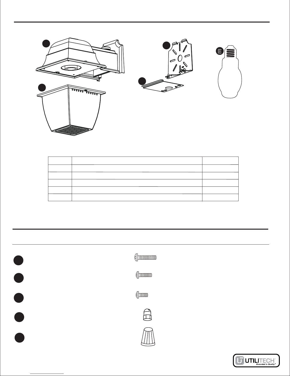
PACKAGE CONTENTS
3
Part Description Quantity
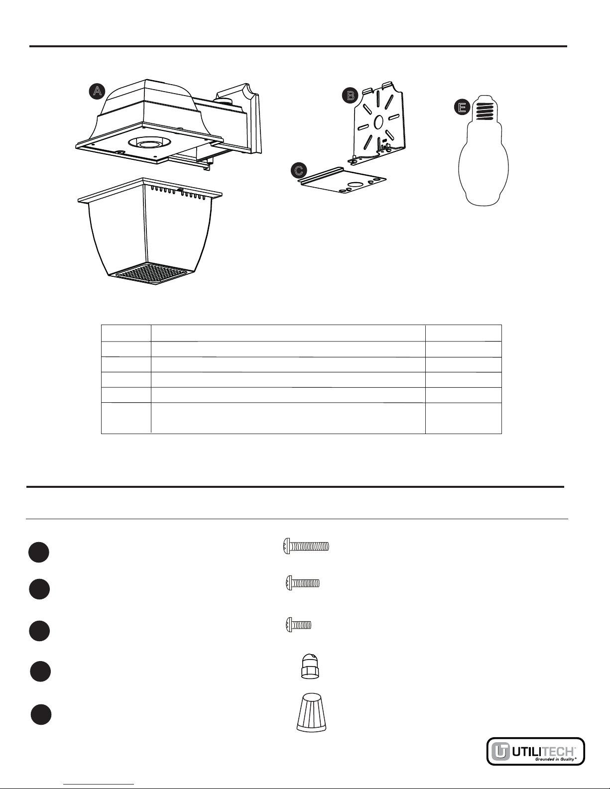
A
B
C
D
E
Light Fixture
Mounting Plate (preinstalled)
Cover Plate (preinstalled)
70-watt Metal Halide Type M98/E Bulb (inside lens)
1
1
1
1
1
Lens (preinstalled)
HARDWARE CONTENTS
Quantity Picture
(Shown to size)
Part Description
E
AB
C
D
2
AA
AA
Wire Nut 3
EE
2
DD
8-32 x 3/4 in. Screw
Decorative Nut
(preinstalled)
2
AA
BB M4 x 18 Screw
(preinstalled)
4
AA
CC M4 x 8 Screw
(preinstalled)
Lowes.com
PREPARATION
Before beginning assembly of product, make sure all parts are present. Compare parts with
package contents list and diagram above. If any part is missing or damaged, do not attempt to
assemble the product. Contact customer service for replacement parts.This light fixture is
designed to fit standard junction boxes as defined by the National Electrical Code. As an
alternative, this light fixture maybe installed using conduit connection. Please contact a qualified
electrician if you have any questions regarding the installation. If any part is missing or damaged,
or you are unsure how to proceed with assembly, do not attempt to install or use the product.
Estimated Assembly Time: 30 - 60 minutes
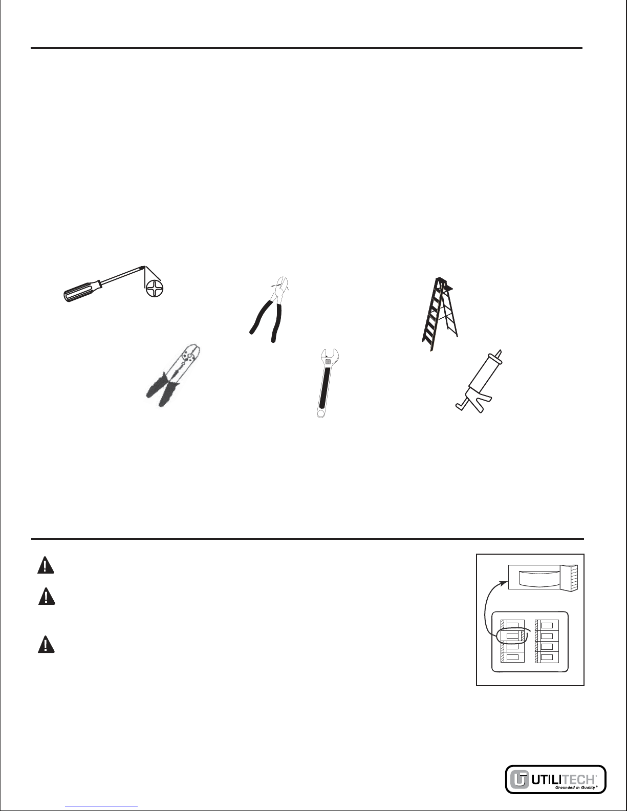
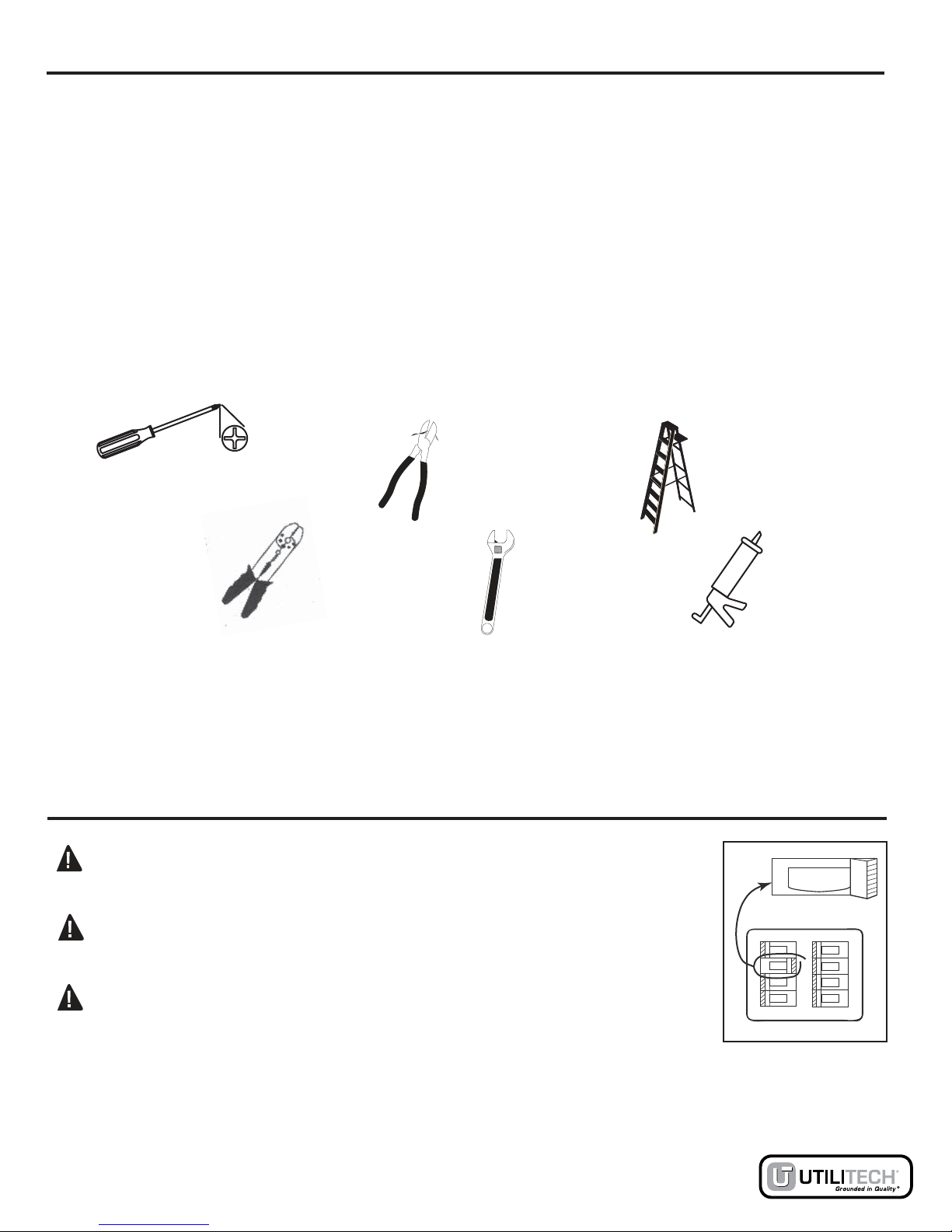
Tools Required for Assembly (not included): Phillips screwdriver, small adjustable wrench, wire
cutters/strippers, step ladder, silicone.
4
DANGER: Fixture must be connected to a 120-volt, 60-hertz power source.
DANGER: Turn power off at the circuit breaker or fuse box before
starting installation!
DANGER: DO NOT rely on wall switch alone to turn off power.
INSTALLATION INSTRUCTIONS
ON
ON
ON
OFF
ON
ON
ON
ON
OFF
Lowes.com

INSTALLATION INSTRUCTIONS continued
5
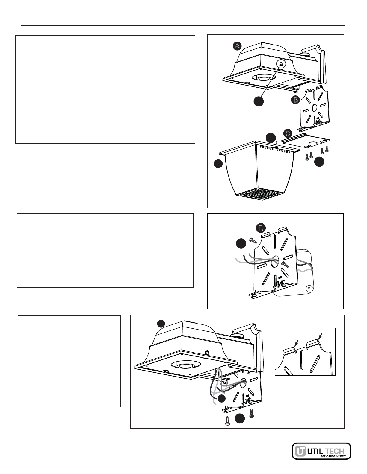
Step 1: Remove preinstalled hardware and parts.
Using a small adjustable wrench, remove two lens
decorative nuts (DD), then gently pull down lens (D).
Using a Phillips screwdriver, remove two cover plate
screws (CC) and cover (C).
Remove two mounting plate screws (CC) and
mounting plate (B).
Step 2: Attach mounting plate.
Pass wiring from preinstalled electrical junction box
through the center hole of (B). Using a Phillips
screwdriver and the two mounting screws (AA)
provided, attach (B) to preinstalled standard
electrical junction box.
Step 3: Attach light fixture.
Attach light fixture (A) by
sliding top of fixture over top
of (B) catching locking tabs.
Using a Phillips screwdriver
secure with two (CC)
removed in step 1.
A
B
B
D
DD
A
B
Locking Tabs
AA
BB
DD
C
DCC
AA
CC
Fig. 1
Fig. 2
Fig. 3
NOTE: DO NOT REMOVE SCREWS (BB).
Lowes.com
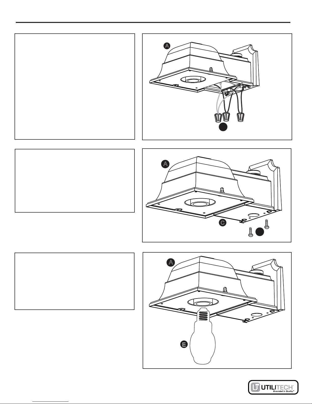
INSTALLATION INSTRUCTIONS continued
6
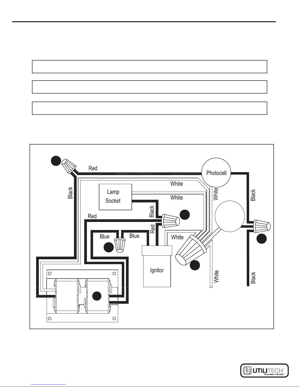
Connect the ground wire from the fixture
and the supply ground wire by twisting a
wire nut (EE) onto the bare ends of the
wires. Connect the white wire from the
junction box to the white wire from the
fixture by twisting (EE) onto the bare ends
of the wires. Connect the black wire from
the junction box to the black wire on the
fixture by twisting (EE) onto the bare ends
of the wires.
Step 5: Attach cover plate.
Carefully slide cover plate (C) into
position placing wiring into rear
compartment of the light fixture (A).
Using a Phillips screwdriver secure the
cover plate (C) with the two (CC)
removed in step 1.
Step 6: Install bulb.
Using a towel or clean glove screw the
70-watt metal halide type M98/E bulb (E)
supplied clockwise into receptacle. Do
not touch the bulb with bare hands; this
may shorten the life of the bulb.
E
Step 4: Connect supply wiring.
A
A
A
EE
AA
CC
C
Fig. 4
Fig. 5
Fig. 6
Lowes.com

Step 9: Energize light fixture.
Turn on power at the circuit breaker and
flip the wall switch ON. The wall switch
must remain ON for the Dusk to Dawn
photocell to operate properly.
DANGER: Fixture must be connected to a 120-volt, 60-hertz power source.
INSTALLATION INSTRUCTIONS continued
7
Step 8: Weather seal light fixture.
After mounting the fixture, apply silicone
sealant caulking compound (sold
separately) completely around the
perimeter of the fixture where the back of
the mounting plate meets the mounting
surface. Silicone caulking prevents water
from entering the junction box.
E CCSILI N
OAKLU
Step 7: Replace lens.
Replace (D) onto light fixture. Using a
wrench, gently secure (DD) to (BB).
DO NOT OVERTIGHTEN!
D
DD
BB
Fig. 8
Fig. 7
Lowes.com
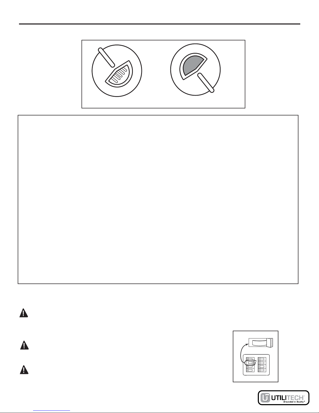
OPERATING INSTRUCTIONS
llawehT.erutxifehtfopotnollecotohpelbatsujdanahtiwdedivorpsithgiLnwaD-ot-ksuDruoY
.ylreporpetarepootllecotohpnwaDotksuDehtrofnoitisopNOehtniniamertsumhctiws
For Dusk to Dawn operation, adjust the photocell knob so that photocell window is fully open (you
will be able to see the photocell circuit through the small opening in the knob). In this mode of
.gninromtxenehtniagaffonrutdnathgintanoemoclliwthgileht,noitarepo
As an alternative to the Dusk to Dawn operation, the light fixture can be operated by a wall switch
as an ON/OFF light fixture. The photocell will need to be adjusted so that the photocell window is
completely covered.
NOTE: semittnereffidtaetavitcathgimdna,emitton,thgiltneibmagnitcetedybkrowsllecotohP
tcaeryamr
ehtohcaeraensthgil,yltnereffidtcaeryamnoitacolynanillecotohphcaE.yadhcae
llecotohprofemitgaltrohsasierehT.semittnereffidtaFFOogroNOemocdnayltnereffid
ehtgnirudtsetoT.gnitsetnehwemitnoitcaersetunimfoelpuocawollaoterusebosnoitavitca
day completely cover photocell with a cloth, cardboard, tape, etc. Photocell operation can be
ehtfoerutxetdnaroloc,egailofybraen,sgnahrevomorfedahs,snosaes,sduolcybdetceffa
.deviecerthgilfotnuomaehtstceffatahtnoitidnocrehtoynaroecafrusgnitnuom
NOTE: This Dusk-to-Dawn Light is provided with a 70-watt metal halide type M98/E bulb. When
turning on it will take several minutes for the bulb to reach full brightness.
Photocell operation.
Bulb Replacement. See installation step 6
WARNING: Your Dusk-to-Dawn Light is designed to operate safely with a 70-watt metal halide
.ylnoblubE/89MepytedilaHlateMttaw-07ahtiwecalpeR.blubE/89Mepyt Installation
of any other bulb type may cause damage to the fixture.
8
erofebxobesufrorekaerbtiucricehttafforewopnruT:REGNAD
replacing bulb.
.rewopffonrutotenolahctiwsllawnoylerTONOD:REGNAD
ON
ON
ON
OFF
ON
ON
ON
ON
FF
O
nepOylluF Fully Closed Fig. 9
Lowes.com
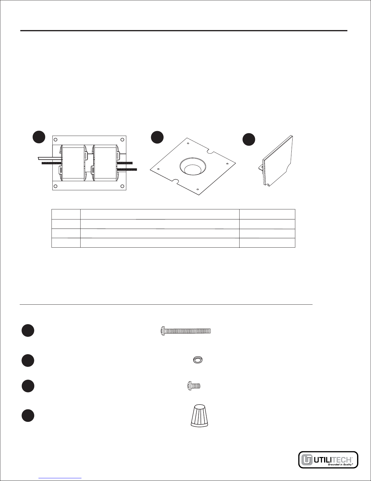
Part Description Quantity
SA
SB
SC
Ballast
Reflector
Thermal Barrier
1
1
1
CARE AND MAINTENANCE
Ballast assembly replacment.
9
Quantity Picture
(Shown to size)
Part Description
M4 x 40
Screw 4
SD
M4
Washer 4
SE
Wire Nut 5
SG
M4 x 6
Screw 4
SF
SA SB SC
Ballast assembly parts are installed and tested at the time of manufacture. No fur-
ther user assembly is needed.
Use a qualified electrician.
Ballast sub-assembly parts
Lowes.com
The ballast assembly can be replaced without the cutting of any wires. Use a qualified electrician.
Perform ballast replacement after removing light fixture from the wall.
10
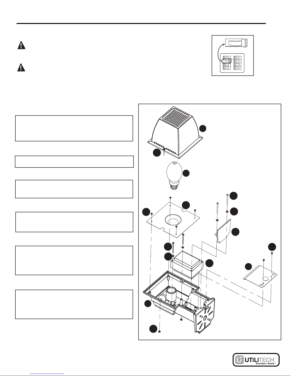
CARE AND MAINTENANCE
Ballast assembly replacment.
Step 1: Remove lens (D) by removing the
two decorative nuts (DD).
Step 2: Remove bulb (E).
Step 3: Remove reflector (SB) by removing
four screws (SF).
Step 4: Remove cover plate (C) by remov-
ing two screws (CC).
DANGER: Turn power off at the circuit breaker or fuse box before
starting balast replacement.
DANGER: DO NOT rely on wall switch alone to turn off power.
ON
ON
ON
OFF
ON
ON
ON
ON
OFF
Step 5: Remove thermal barrier (SC) by
removing two screws (SD) and washers
(SE).
E
C
D
A
DD
BB
SF
SB
SD
SD
SE
SE
SA
SC
CC
Step 6: Remove ballast assembly (SA) by
removing two remaining screws (SD) and
washers (SE).
Fig. 10
DO NOT REMOVE SCREWS (BB).
Lowes.com
CARE AND MAINTENANCE continued
Ballast assembly replacment. continued
11
Step 8: Remove wire nuts (SG) and save for new ballast installation.
Step 9: Connect new ballast assembly by reversing steps 1 through 7.
Step 7: Be careful not to damage wires label wires according to wiring diagram.
120 volts alternating current, 60 hertz.
Input
SA
SG
SG
SG
SG
SG
Fig. 11
Capacitor
Lowes.com

TROUBLESHOOTING
Possible CauseProblem
12
Printed in China
TWO YEAR LIMITED WARRANTY
Light will not
come ON. No power to light. Check that the circuit is on, wall
switch is on,there is power to
light fixture.
Photocell aperture allowing too
much light.
Close photocell aperture in
small steps until desired setting
is achieved. See Fig. 10.
Light will not come
ON untill after
complete darkness.
Light will not turn
OFF untill full light.
Photocell aperture not allowing
enough light.
Open photocell aperture in
small steps until desired setting
is achieved. See Fig. 10.
Bulb burned out. Replace bulb with 70-watt metal
halide type M98/E bulb.
Light will not
come ON.
Bulb flickers or will
not fully light. Ballast failing. Replace ballast. See Ballast
assembly replacement.
If this product (excluding bulbs) fails due to a defect in materials or workmanship within two (2) years
from the date of purchase, return it along with the proof of date of purchase to place of purchase and
it will be replaced with the same or comparable model free of charge.
This warranty gives you specific legal rights and you may have other rights that vary from state to
state. This warranty is void if damage or defect has resulted from accident, abuse, misuse or faulty
repair.
IN NO EVENT WILL THE MANUFACTURER BE LIABLE FOR ANY CONSEQUENTIAL, SPECIAL
INCIDENTAL OR INDIRECT DAMAGES OF ANY KIND ARISING OUT OF THE USE OR MISUSE OF
THIS PRODUCT. SOME STATES DO NOT ALLOW THE EXCLUSION OR LIMITATION OF
INCIDENTAL OR CONSEQUENTIAL DAMAGES SO THE ABOVE EXCLUSION OR LIMITATION
MAY NOT APPLY TO YOU.
THIS EQUIPMENT HAS BEEN FOUND TO COMPLY WITH THE LIMITS FOR A CLASS B DIGITAL
DEVICE, PURSUANT TO PART 15 OF THE FCC RULES. THESE LIMITS ARE DESIGNED TO
PROVIDE REASONABLE PROTECTION AGAINST HARMFUL INTERFERENCE IN A RESIDENTIAL
INSTALLATION. THIS EQUIPMENT GENERATES, USES AND CAN RADIATE RADIO FREQUENCY
ENERGY AND IF NOT USED IN ACCORDANCE WITH THE INSTRUCTIONS, MAY CAUSE HARMFUL
INTERFERENCE TO RADIO COMMUNICATIONS. HOWEVER, THERE IS NO GURANTEE THAT
INTERFERENCE WILL NOT OCCUR IN A PARTICULAR INSTALLATION.
Corrective Action
Lowes.com
Utilitech & UT design® is a registered
trademark of LF, LLC. All Rights Reserved.

ARTICLE #0156847
MODÈLE #DC209H-28
LUMINAIRE CRÉPUSCULAIREAUX
HALOGÉNURES MÉTALLISÉS
JOIGNEZ VOTRE REÇU ICI
Numéro de série Date d’achat
Des questions, des problèmes, des pièces manquantes? Avant de retourner l’article au
détaillant, appelez notre service à la clientèle au 1-866-994-4148, entre 8 h et 18 h (HNE),
du lundi au jeudi, ou entre 8 h et 17 h (HNE) le vendredi.
Lowes.com

14
TABLE DES MATIÈRES
Consignes de sécurité .................................................................................................................
Contenu de l’emballage ...............................................................................................................
Préparation ..................................................................................................................................
Instructions pour l’installation ......................................................................................................
Mode d’emploi .............................................................................................................................
Entretien ......................................................................................................................................
Dépannage .................................................................................................................................
Garantie ......................................................................................................................................
15
15
16
16
20
21
24
24
CONSIGNES DE SÉCURITÉ
Veuillez vous assurer de lire et de comprendre l’intégralité de ce guide avant d’assembler,
d’utiliser ou d’installer ce produit.
Définition des mots indicateurs de danger :
DANGER : Cette mention indique un risque potentiel qui, s’il n’est pas éliminé, pourrait
provoquer des blessures graves, voire mortelles.
AVERTISSEMENT : Cette mention indique un risque potentiel qui, s’il n’est pas éliminé,
pourrait entraîner des dommages au produit.
AVERTISSEMENT : VEUILLEZ LIRE ET VOUS ASSURER DE COMPRENDRE TOUTES
LES CONSIGNES DE SÉCURITÉ ET LE MODE D’EMPLOI DANS CE GUIDE AVANT DE
TENTER D’ASSEMBLER, D’INSTALLER OU DE FAIRE FONCTIONNER CE PRODUIT.
DANGER : Faites appel à un électricien qualifié si vous n’êtes pas certain de la marche
à suivre pour l’installation. Veillez à ce que le câblage soit installé conformément au Code
national de l’électricité ou, au Canada, au Code canadien de l’électricité. Effectuez toujours
toutes les connexions électriques de façon quelles soient conformes aux codes du
bâtiment locaux, aux règlements locaux et au code national de l’électricité. Veuillez
communiquer avec un électricien qualifié si vous avez des questions au sujet de l’installation.
DANGER : Assurez-vous que le luminaire est branché sur une source d’alimentation de
120 volts et 60 hertz.
DANGER : Avant d’installer le produit, coupez l’électricité du panneau central de disjoncteurs
ou de fusibles!
DANGER : NE vous fiez PAS uniquement à l’interrupteur mural pour couper l’alimentation
électrique.
VEUILLEZ LIRE TOUTES LES INSTRUCTIONS! CONSERVEZ CES DIRECTIVES!
Lowes.com
CONTENU DE L’EMBALLAGE
15
Pièce Description Quantité
A
B
C
D
E
Luminaire
Traverse (déjà installée)
Plaque du boîtier (déjà installée)
Ampoule aux halogénures métallisés de 70 watts
de type M98/E (à l’intérieur de la lentille).
1
1
1
1
1
Lentille (préinstallée)
QUINCAILLERIE INCLUSE
Quantité Illustration
(grandeur réelle)
Pièce Description
E
AB
C
D
2
AA
AA
Capuchon de
connexion
3
EE
2
DD
Vis de 8/32 po x 3/4 po
Écrou décoratif
(déjà installé)
2
AA
BB Vis M4 de 18 mm
(déjà installée)
4
AA
CC Vis M4 de 8 mm
(déjà installée)
Lowes.com
PRÉPARATION
Avant de commencer l’assemblage du produit, assurez-vous d’avoir toutes les pièces. Comparez
les pièces dans l’emballage avec la liste et le tableau ci-dessus. S’il y a des pièces manquantes
ou endommagées, ne tentez pas d’assembler le produit. Communiquez avec le service à la
clientèle pour obtenir des pièces de rechange. Ce luminaire est conçu pour être connecté aux
boîtes de jonction standard en vertu du Code national de l’électricité. Vous pouvez également
l’installer à l’aide de conduits de câbles. Veuillez communiquer avec un électricien qualifié si vous
avez des questions au sujet de l’installation. S’il y a des pièces manquantes ou endommagées,
ou que vous n’êtes pas certain de la méthode d’assemblage à suivre, n’essayez pas d’installer ni
d’utiliser le produit.
Temps d’assemblage approximatif : de 30 à 60 minutes
Outils nécessaires pour l’assemblage (non inclus) : tournevis cruciforme, petite clé à molette,
coupe-fil ou pince à dénuder, escabeau et silicone.
16
DANGER : Assurez-vous que le luminaire est branché sur une source
d’alimentation de 120 volts et 60 hertz.
DANGER : Avant d’installer le produit, coupez l’électricité du panneau
central de disjoncteurs ou de fusibles!
DANGER : NE vous fiez PAS uniquement à l’interrupteur mural pour
couper l’alimentation électrique.
INSTRUCTIONS POUR L’INSTALLATION
ON
ON
ON
OFF
ON
ON
ON
ON
OFF (arrêt)
Lowes.com
INSTRUCTIONS POUR L’INSTALLATION (suite)
17
Étape 1 : Retrait de la quincaillerie et de toutes les
pièces déjà installées
À l’aide d’une petite clé à molette, puis tirez
doucement vers le bas les lentilles (D).
NOTE: NE PAS RETIRER LES VIS
À l’aide d’un tournevis cruciforme, retirez les deux
vis de la plaque du boîtier (CC), ensuite la plaque
elle-même (C).
Retirez les deux vis de la traverse (CC),
retirez ensuite la traverse (B) elle-même.
Étape 2 : Installation de la traverse
Faites passer dans le trou central de la traverse (B)
le câblage de la boîte de jonction électrique déjà
installée. À l’aide d’un tournevis cruciforme et de
deux vis de montage (AA) fournies, fixez la traverse
(B) à la boîte de jonction électrique standard déjà
installée.
Étape 3 : Fixation du luminaire
Fixez le luminaire (A) en le
glissant sur la traverse (B)
jusqu’aux languettes de
verrouillage. À l’aide d’un
tournevis cruciforme,
remettez les deux vis (CC)
que vous aviez retirées à
l’étape 1 et serrez-les.
A
B
B
D
DD
A
B
Languettes de verrouillage
AA
BB
DD
C
DCC
AA
CC
Figure 1
Figure 2
Figure 3
Lowes.com

INSTRUCTIONS POUR L’INSTALLATION (suite)
18
Connectez le fil de mise à la terre du
luminaire au fil de mise à la terre de
l’alimentation en fixant par torsion dans
un capuchon de connexion (EE) les bouts
dénudés des fils. Connectez le fil blanc de
la boîte de jonction électrique au fil blanc
du luminaire en fixant par torsion dans un
capuchon de connexion (EE) les bouts
dénudés des fils. Connectez le fil noir de
la boîte de jonction électrique au fil noir
du luminaire en fixant par torsion dans
un capuchon de connexion (EE) les bouts
dénudés des fils.
Étape 5 : Installation de la plaque
du boîtier
Glissez doucement la plaque du boîtier
(C) pour l’installer, en plaçant le
câblage dans le compartiment arrière
du luminaire (A). À l’aide d’un tournevis
cruciforme, fixez la plaque du boîtier
(C) en remettant les deux vis (CC) que
vous aviez retirées à l’étape 1 et en les
serrant.
Étape 6 : Installation de l’ampoule
À l’aide d’une serviette ou d’un gant
propre, vissez dans le sens des aiguilles
d’une montre l’ampoule aux halogénures
métallisés de 70 watts de type M98/E
(fournie). Ne touchez pas l’ampoule avec
les mains nues : cela pourrait raccourcir
sa durée de vie utile.
E
Étape 4 : Branchement du câblage
d’alimentation A
A
A
EE
AA
CC
C
Figure 4
Figure 5
Figure 6
Lowes.com

Étape 9 : Mise sous tension du luminaire
Établissez le courant depuis le panneau
de disjoncteurs et faites basculer
l’interrupteur mural en position « ON ».
L’interrupteur mural doit demeurer en
position « ON » pour que la cellule
photoélectrique « crépusculaire »
fonctionne adéquatement.
DANGER :Assurez-vous que le luminaire est branché sur une source d’alimentation
de 120 volts et 60 hertz.
INSTRUCTIONS POUR L’INSTALLATION (suite)
19
Étape 8 : Pose d’un enduit résistant aux
intempéries
Après avoir installé le luminaire,
appliquez un produit de calfeutrage à
base de silicone (vendu séparément)
sur le périmètre du luminaire, là où la
traverse s’appuie sur la surface de
montage. Le calfeutrant à base de
silicone empêche l’eau de s’infiltrer
dans la boîte de jonction.
CALFEUTRANT À
BASE DE SILICONE
Étape 7 : Remise en place de la lentille
Replacez la lentille (D) pour la fixer au
luminaire. En utilisant une clé
délicatement sécurisé (DD) à (BB).
NE SERREZ PAS EXCESSIVEMENT!
D
DD
BB
Figure 8
Figure 7
Lowes.com

MODE D’EMPLOI
DD
Votre luminaire « crépusculaire » est muni d’une cellule photoélectrique réglable située sur le dessus du
boîtier. L’interrupteur mural doit demeurer en position « ON » pour que la cellule photoélectrique
« crépusculaire » fonctionne adéquatement.
Pour un fonctionnement du crépuscule jusqu’à l’aube, placez le bouton de manière à ce que la fenêtre de la
cellule photoélectrique soit complètement ouverte (vous verrez ainsi le circuit de la cellule photoélectrique à
travers la petite ouverture pratiquée dans le bouton).
llule photoélectrique
Au lieu du mode de fonctionnement du crépuscule à l’aube, vous pouvez faire fonctionner votre luminaire
comme un luminaire ordinaire à l’aide d’un interrupteur mural. Vous devez régler la ce
en fermant complètement sa fenêtre.
REMARQUE : Les cellules photoélectriques fonctionnent par détection de la lumière ambiante, et non à
l’aide d’une minuterie. Elles peuvent donc être activées chaque jour à des moments différents. Chaque
cellule photoélectrique se trouvant dans un certain endroit peut réagir différemment d’une autre, les
luminaires près les uns des autres peuvent réagir différemment et ils peuvent s’allumer ou s’éteindre à des
moments différents. L’activation de la cellule photoélectrique se fait après un court délai. Par conséquent,
lorsque vous testez votre luminaire, vous devez attendre quelques minutes avant qu’il ne réagisse. Pour
tester votre luminaire pendant le jour, couvrez complètement la cellule photoélectrique avec un linge, un
carton, du ruban-cache, etc. Le fonctionnement de la cellule photoélectrique peut être influé par les nuages,
les saisons, l’ombre créée par les saillies ou le feuillage, la couleur et la texture de la surface sur laquelle le
luminaire est installé, ou toute autre situation qui peut influer sur la quantité de lumière.
REMARQUE : Une ampoule aux halogénures métallisés de 70 watts de type M98/E est fournie avec ce
luminaire « crépusculaire ». Lorsque vous allumez le luminaire, vous devez attendre plusieurs minutes avant
que l’ampoule n’atteigne sa pleine intensité lumineuse.
Fonctionnement de la cellule photoélectrique
Changement de l’ampoule. Consultez l’étape d’installation 6.
AVERTISSEMENT : Votre luminaire « crépusculaire » est conçu pour fonctionner de façon sécuritaire
avec une ampoule aux halogénures métallisés de 70 watts de type M98/E. Remplacez l’ampoule
grillée uniquement par une ampoule aux halogénures métallisés de 70 watts de type M98/E.
Vous pourriez endommager le luminaire en installant tout autre type d’ampoules.
20
DANGER : Avant de changer d’ampoule, coupez l’électricité du
panneau central de disjoncteurs ou de fusibles.
DANGER : NE vous fiez PAS uniquement à l’interrupteur mural pour couper
l’alimentation électrique.
ON
ON
ON
OFF
ON
ON
ON
ON
Complètement
ouverte Complètement
fermée Figure 9
Lowes.com
Table of contents
Languages:
Other Utilitech Outdoor Light manuals


Popular Outdoor Light manuals by other brands


BEGA
BEGA 33 592 Instructions for use

Nemo Studio
Nemo Studio LUX W-S Mounting instructions

ASTRO
ASTRO Richmond 285 instructions

louis poulsen
louis poulsen Flindt Garden Spike Adapter Box Mounting instruction

Urban Electric
Urban Electric CAY Assembly and mounting instructions

Prilux
Prilux Greco instruction manual


