Utility Relay Company AC-PRO-II User manual

Chagrin Falls, OH 44023
Phone: 888.289.2864
www.utilityrelay.com
I-AC-PRO-II AC TRIP UNIT
A C -P R O -II
®
S
TATE
OF
THE
ART
TECHNOLOGY
FOR
LOW
VOLTAGE
CIRCUIT
BREAKER
RETROFITTING
IN STRU C TIO N m A N U A L


AC-PRO-II® Instruction Manual www.utilityrelay.com
Page 1
Manual Revision 1.4
Section: Page
1.0 Introduction and Product Overview..........................3
1.1 Current Protection and Functions......................3
1.2 Voltage and Power Features - optional Voltage
Divider Module (VDM) ......................................3
1.3 Additional Features...........................................3
2.0 UL/ULC Classification & CE Mark.............................4
3.0 Trip Unit Power..........................................................4
3.1 Current Transformer (CT) Power ......................4
3.2 Battery Power...................................................4
3.3 USB Power.......................................................4
3.4 24VDC Auxiliary Power.....................................4
3.5 Voltage Divider Module (VDM) Power (option)..4
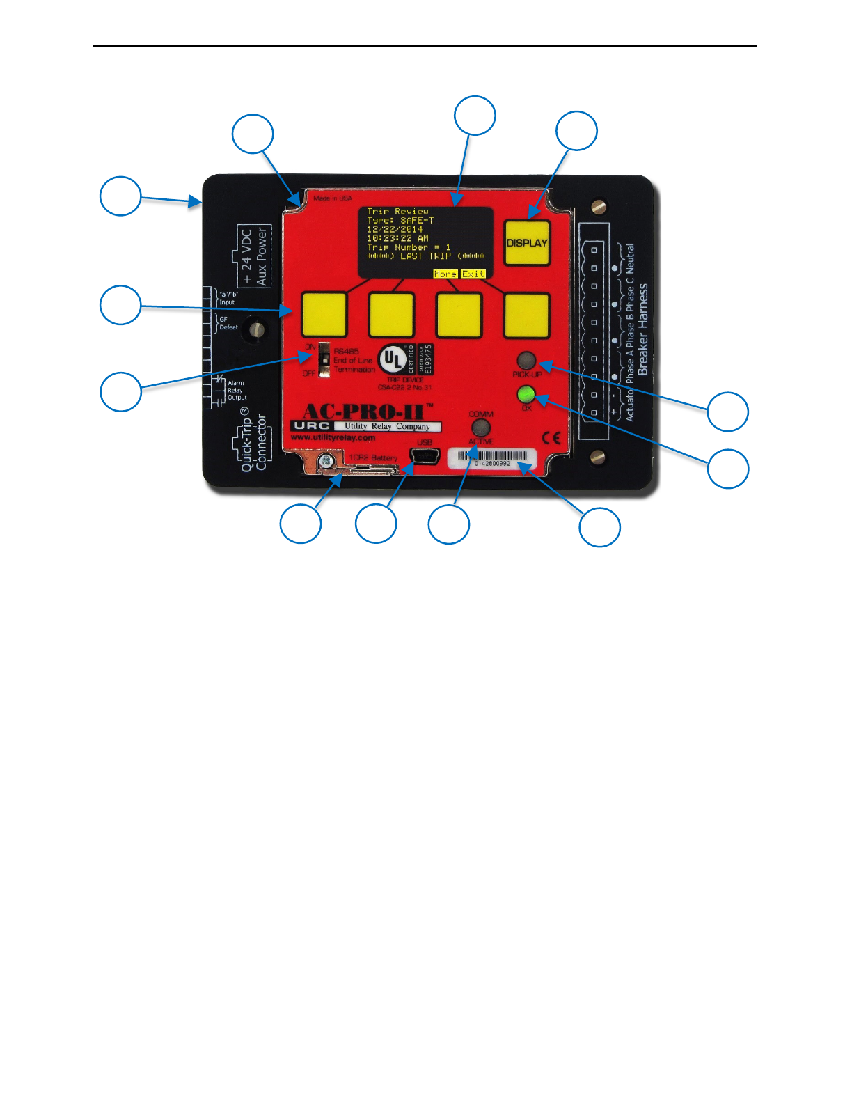
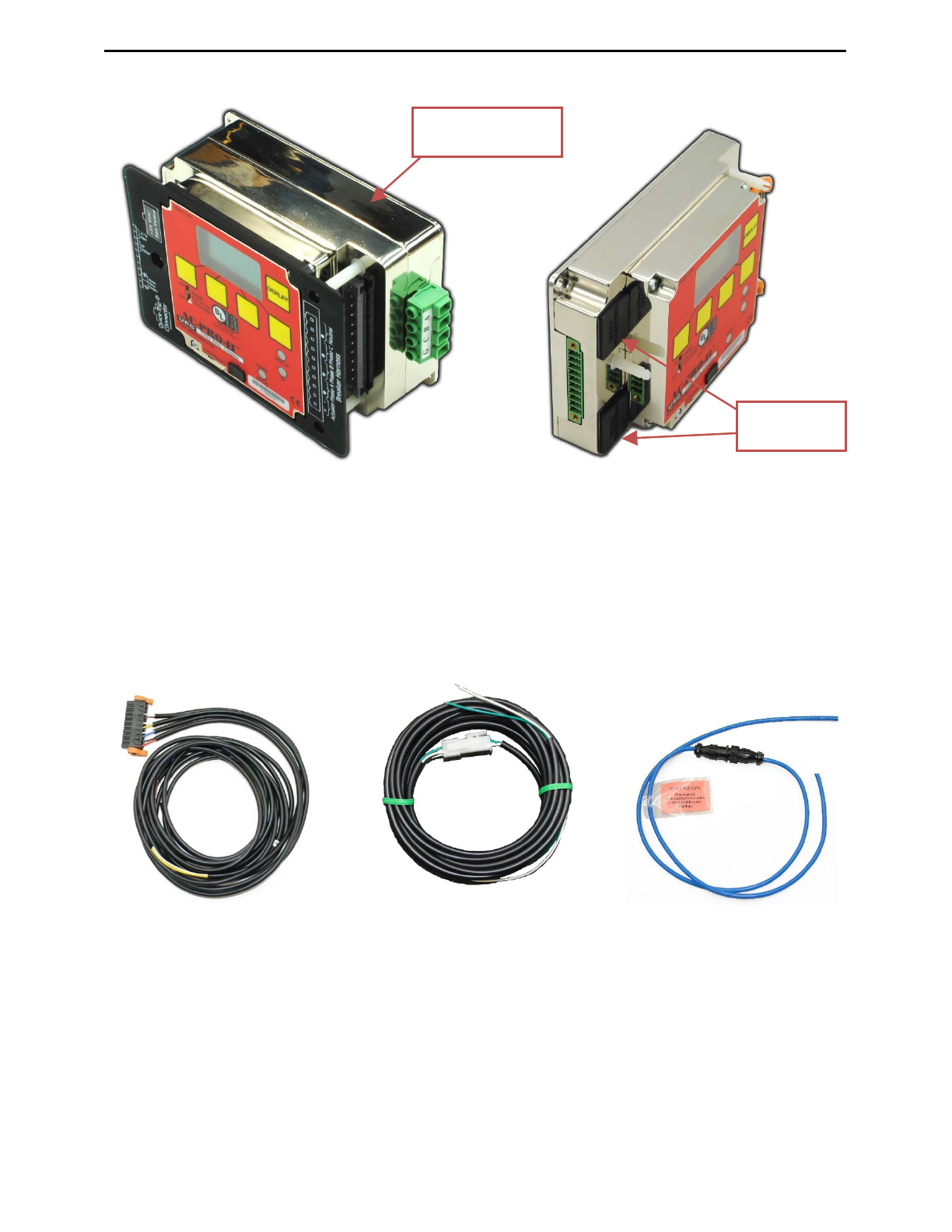
4.0 AC-PRO-II® Pictures and Configurations..................5
5.0 External Connections................................................8
5.1 Breaker Wiring Harness..................................11
5.1.1 Ground Fault Wiring Configurations ....11
5.2 QUICK-TRIP®Connector................................11
5.3Auxiliary Connections .....................................11
5.3.1 Configurable Alarm Relay ...................11
5.3.2 Ground Fault Defeat Input...................12
5.3.3 URC Breaker Position Switch..............12
5.4 RS-485 Communications Terminal Block........12
5.5 24VDC Auxiliary Power...................................12
5.6 USB Port ........................................................12
5.6.1 USB Extension cable ..........................12
5.6.2 USB Extension Cable Installation........13
5.7 VDM Connections (optional)...........................13
6.0 Menu Navigation......................................................13
6.1 Power Menu ...................................................16
6.2 Settings Menu.................................................16
6.3 Trip History Menu ...........................................16
6.4 More Menu .....................................................16
6.4.1 Time and Date Setting ........................16
6.4.2 Battery Test and Status.......................17
7.0 QUICK-TRIP®System (optional)..............................18
7.1 QUICK-TRIP®Basics & Operation..................18
7.2 AC-PRO-II QUICK-TRIP®Switch Mounting.....19
7.3 Remote QUICK-TRIP®Switch.........................19
7.4 QUICK-TRIP®Remote Indication....................19
8.0 Voltage Divider Module (VDM) (optional)...............20
9.0 SAFE-T-TRIPTM (optional)........................................20
10.0 Sluggish BreakerTM Detection .................................20
11.0 Commissioning the AC-PRO-II®..............................21
11.1 Powering-Up the Trip Unit for Commissioning.21
11.1.1 Internal Battery....................................21
11.1.2 USB Power.........................................21
11.1.3 24VDC Auxiliary Power.......................21
11.2 Un-commissioned Screen...............................21
11.3 Entering & Changing Settings locally..............22
11.4 Security Code.................................................25
11.5 CT Tap...........................................................25
11.6 CT Secondary Rating .....................................25
11.7 Power Flow Direction......................................25
11.8 Frequency ......................................................25
11.9 Long Time (LT)...............................................25
11.10Thermal Memory ............................................25
11.11Short-Time (ST)..............................................25
11.12Instantaneous (I).............................................25
11.13Ground Fault (GF) Protection..........................26
11.14Neutral Overload (NOL) Settings ....................26
11.15QUICK-TRIP®Instantaneous (QT-I)................26
11.16QUICK-TRIP Ground Fault (QT-GF)...............26
11.17Undervoltage (UV)..........................................27
11.18Overvoltage (OV)........................................... 27
11.19Sluggish Breaker Setting................................ 27
11.20Configurable Alarm Relay Settings................. 27
11.21Breaker Position Contact Type Setting........... 27
11.22Saving Settings.............................................. 27
11.23Settings Verification ....................................... 27
11.24Settings Review ............................................. 28
11.25Time & Date Settings ..................................... 28
11.26Communications Settings............................... 28
12.0 Trip History.............................................................. 29
13.0 Normal Operations & Readings.............................. 31
14.0 Testing..................................................................... 31
14.1 Commission the Trip Unit............................... 31
14.2 Long Time Trip Test....................................... 31
14.3 Short Time Trip Test ...................................... 32
14.4 Instantaneous Trip Test.................................. 32
14.5 Neutral Overload (NOL) Trip Test................... 32
14.6 Ground Fault Trip Tests ................................. 32
14.6.1 Residual Ground Fault Trip Test......... 32
14.6.2 Ground Return Fault Trip Test............ 32
14.7 QT-GF Trip Test............................................. 32
14.8 CT Phasing Test for GF ................................. 32
14.9 QT-I Trip Test................................................. 33
14.10Undervoltage (UV) Test.................................. 33
14.11Overvoltage (OV) Test ................................... 34
15.0 Secondary Injection Testing................................... 34
15.1 Secondary Injection Test Set.......................... 34
15.2 Standard Relay Test Set................................ 34
15.3 LT Delay Testing Chart .................................. 35
15.4 Neutral Overload Testing Chart...................... 36
16.0 Ratings & Physical Information.............................. 36
17.0 Warranty .................................................................. 37
18.0 Time-Current Curves (TCC).................................... 37
18.1 Long Time (LT) Trip Time............................... 37
18.2 Short Time (ST) Trip Time.............................. 38
18.3 Ground Fault (GF) Trip Time.......................... 40
18.4 Neutral Overload (NOL) Trip Time.................. 40
18.5 Current Metering Accuracy............................. 44
19.0 Voltage & Power Calculations................................ 44
20.0 Error and Alarms..................................................... 44
20.1 Internal Error.................................................. 44
20.2 Actuator Open Circuit..................................... 44
20.3 Alarm Screens ............................................... 44
20.4 Un-Calibrated................................................. 44
21.0 Battery ..................................................................... 45
21.1 Checking the Battery Voltage......................... 45
21.2 Battery Replacement...................................... 45
22.0 Rotating the Display................................................ 45
23.0 InfoPro-ACTM Software Application........................ 46
23.1 Firmware Versions and Updates .................... 46
24.0 Communications..................................................... 49
24.1 Communications Introduction......................... 49
24.2 Communications Components ....................... 49
24.3 Communications Wiring ................................. 49
24.4 System Components & Computer Hardware.. 49
24.4.1 Ethernet.............................................. 49
24.4.2 LCI Ethernet....................................... 49
24.5 Trip Unit Programming................................... 50
24.6 Modbus Registers.......................................... 50
For latest version, visit:
http://www.utilityrelay.com/Side_Bar/Instruction_Manuals.html
Table of Contents

AC-PRO-II®Instruction Manual www.utilityrelay.com
Page 2
List of Tables and Figures
Figure Page
Figure 4.1 AC-PRO-II Front View - Horizontal Configuration........................................................................................................5
Figure 4.2: AC-PRO-II Front View - Vertical Configuration with Breaker Harness at bottom...................................................... 6
Figure 4.3: AC-PRO-II Side View (without VDM)............................................................................................................................6
Figure 4.4: AC-PRO-II Angled Views – with and without VDM......................................................................................................7
Figure 4.5: AC-PRO-II connectors and cables ...............................................................................................................................7
Figure 5.1: AC-PRO-II External Connections - Vertical Bottom Configuration............................................................................8
Figure 5.2: Voltage Divider Module (VDM) External Connections................................................................................................9
Figure 5.3: AC-PRO-II Typical Wiring Diagram............................................................................................................................10
Figure 5.4: AC-PRO-II Typical Ground Return Wiring Diagram ..................................................................................................11
Figure 5.5: USB Extension cable..................................................................................................................................................12
Figure 5.6: USB Extension Plate Drilling......................................................................................................................................13
Figure 5.7: USB Extension Plate & Cable Installation.................................................................................................................13
Figure 6.1: Main Screen.................................................................................................................................................................13
Figure 6.2: Typical AC-PRO-II Menu Navigation Map - Simple View........................................................................................... 15
Figure 6.3: Power Menu Screens..................................................................................................................................................16
Figure 6.4: Settings Menu first screen .........................................................................................................................................16
Figure 6.5: MORE Menu.................................................................................................................................................................17
Figure 7.1: QUICK-TRIP System and Connections......................................................................................................................18
Figure 7.2: AC-PRO-II QUICK-TRIP Switch Drilling Plan.............................................................................................................19
Figure 7.3: QUICK-TRIP Switch Mounting....................................................................................................................................19
Figure 7.4: AC-PRO-II QUICK-TRIP Switch...................................................................................................................................19
Figure 9.1: SAFE-T-TRIP ...............................................................................................................................................................20
Figure 9.2: SAFE-T-TRIP in case...................................................................................................................................................20
Figure 10.1: Sluggish Breaker Screen..........................................................................................................................................21
Figure 11.1: Un-commissioned Screen ........................................................................................................................................21
Figure 11.2: Change Settings Menu - Part 1.................................................................................................................................22
Figure 11.3: Change Settings Menu - Part 2.................................................................................................................................23
Figure 11.4: Change Settings Menu - Part 3.................................................................................................................................24
Figure 11.5: Settings Screen - Review Button .............................................................................................................................28
Figure 11.6: Communications Settings........................................................................................................................................28
Figure 12.1: Trip History Menu .....................................................................................................................................................30
Figure 13.1: Main (“Readings”) Screen........................................................................................................................................31
Figure 13.2: Power Screen #1:......................................................................................................................................................31
Figure 13.3: Power Screen #2: Energy.........................................................................................................................................31
Figure 14.1: Phase A & B, CT Polarity Test..................................................................................................................................33
Figure 14.2: Phase B & C, CT Polarity Test..................................................................................................................................33
Figure 14.3: Undervoltage Test.....................................................................................................................................................33
Figure 14.4: Overvoltage Test.......................................................................................................................................................34
Figure 15.1: B-292 Secondary Injection Test Set.........................................................................................................................34
Figure 16.1: AC-PRO-II & Quick Trip Switch Drawings and Dimensions...................................................................................36
Figure 18.1: Overload TCC............................................................................................................................................................39
Figure 18.2: Ground Fault (GF) TCC.............................................................................................................................................41
Figure 18.3: Neutral Overload (NOL) TCC....................................................................................................................................42
Figure 18.4: QUICK-TRIP Ground Fault and QUICK-TRIP Instantaneous TCCs ........................................................................43
Figure 20.1: Internal Error Screen ................................................................................................................................................44
Figure 20.2: Actuator Open screen...............................................................................................................................................44
Figure 20.3: Trip Alarm Screen.....................................................................................................................................................44
Figure 20.4: OverVoltage Alarm Screen.......................................................................................................................................44
Figure 20.5: UnderVoltage Alarm Screen.....................................................................................................................................44
Figure 20.6: Clear Alarms Screen.................................................................................................................................................44
Figure 20.7: Un-Calibrated Screen................................................................................................................................................44
Figure 21.1: Battery Door..............................................................................................................................................................45
Figure 22.1: Display Case Screw locations..................................................................................................................................45
Figure 22.2: Trip Unit and Display (separated) ............................................................................................................................46
Figure 23.1: InfoPro-AC Readings Tab Screenshot.....................................................................................................................47
Figure 23.2: InfoPro-AC Waveform Tab Screenshot....................................................................................................................47
Figure 23.3: InfoPro-AC Trip History Tab Screenshot.................................................................................................................48
Figure 23.4: InfoPro-AC Settings Tab Screenshot.......................................................................................................................48
Figure 24.1: Ethernet configuration..............................................................................................................................................50
Figure 24.2: LCI Ethernet Configuration ......................................................................................................................................50
Tables Page
Table 3-A: CT Power-up values ......................................................................................................................................................4
Table 5-A: Alarm Relay Configuration..........................................................................................................................................12
Table 6-A: Common Smart Button Actions..................................................................................................................................14
Table 12-A: Trip Types ..................................................................................................................................................................29
Utility Relay Company
10100 Queens Way
Chagrin Falls, OH 44023
www.utilityrelay.com
Phone 888-289-2864
Fax: 440-708-1177

AC-PRO-II® Instruction Manual www.utilityrelay.com
Page 3
The AC-PRO-II®is a state of the art, micro-controller based
trip unit for use on three phase, 600 Volt class, AC circuit
breakers on 50 Hertz or 60 Hertz systems. The AC-PRO-II
features a rotatable 128 x 64 Multi-line, Organic Light Emitting
Diode (OLED) Display, smart buttons, and LEDs.
The standard AC-PRO-II provides:
•Overload and fault protection
•RS485 communications
•QUICK-TRIP®arc flash hazard reduction ready
•Patented Sluggish Breaker®detection
•Time stamped trip history with waveform capture
•InfoPro-ACTM software interface
•Ready for the SAFE-T-TRIP®hand-held remote trip
device
•And many other features
Additionally, with the optional Voltage Divider Module (VDMTM),
the AC-PRO-II can provide over/under voltage protection and
power calculations.
The AC-PRO-II is 55% smaller than the original AC-PRO®and
including more features and more flexibility. The smaller form
factor allows application on a wider range of breakers. The trip
unit features versatile user settings that allow setting the
frequency (50Hz or 60Hz), CT secondary rating, and Ground
Fault type in the field, eliminating the need for a special factory-
configured trip unit and simplifying the kit ordering process.
The AC-PRO-II is backwards compatible with existing AC-PRO
CTs, actuators, wiring harness, and settings, making direct
replacements easy. Similar to AC-PRO, the AC-PRO-II
settings are entered using simple parameters. No percentages
or multipliers are required. AC-PRO-II settings are
programmed using the easy-to-read multi-line OLED display.
The AC-PRO-II includes the following Current-based features:
Long Time (LT)
Short Time (ST)
Instantaneous (I)
Ground Fault (GF)
Thermal Memory (for LT, ST, & GF)
Neutral Overload (NOL)
QUICK-TRIP Instantaneous (QT-I)
QUICK-TRIP Ground Fault (QT-GF)
Current Metering
Overload (Long Time pickup) Alarm
Instantaneous Override (I-OVRD)
(factory setting – normally disabled)
Instantaneous on Close (I-CLOS)
(factory setting – normally enabled)
The AC-PRO-II measures the true RMS current through
each of the breaker’s three poles.
AC-PRO-II settings include a Ground Fault type setting,
which allows the user to select either Residual Ground Fault
protection (vector sum), or Ground Return Ground Fault
protection (measures GF directly).
The QUICK-TRIP Instantaneous and QUICK-TRIP Ground
Fault protective settings are available to minimize downstream
Arc Flash Hazard.
The AC-PRO-II uses a unique algorithm to determine if the
RMS currents are greater than 12 times the CT rating where
the CTs may be saturated. The AC-PRO-II then corrects the
effect of CT saturation on the Long Time and Short Time trip
functions.
The AC-PRO-II can be provided with an optional Voltage
Divider Module (VDM) attached to the back of the trip unit.
When configured with the VDM, the AC-PRO-II offers the
following Voltage-based features:
•Rated for up to 600V three-phase systems
•Under-Voltage (Brown Out) trip & alarm
•Over-Voltage trip & alarm
•Voltage metering
•Power metering:
(KW, KVA, KWHr, KVAHr, Power Factor)
•VDM provides continuous trip unit power even when the
breaker is open and not carrying current, allowing for
communications, even without CT power.
In addition, the AC-PRO-II also features the following:
(features are standard for all AC-PRO-II trip units unless noted
otherwise)
•Configurable alarm relay (form C)
•Self-Test
•Front USB port for settings upload and download,
SAFE-T-TRIP remote trip device, auxiliary power and
firmware updates
•OLED multi-line display
•RS-485 Modbus RTU communications
•Versatile user settings provide more flexibility than the
original AC-PRO:
o50Hz or 60 Hz operation
oPhase CT secondary ratings:
1A, 0.5A, 0.4A, 0.25A, 0.2A
oNeutral CT secondary ratings:
2A, 1.5A, 1A, 0.5A, 0.4A, 0.25A, 0.2A, 0.18A
oGround Fault type can be set to “Residual” or
“Ground Return” depending on the CT location &
Ground Fault scheme.
•Compact form-factor allows the AC-PRO-II to be used on
a wide range of breakers, including more insulated case
breakers.
•Backwards compatibility with AC-PRO actuators, CT’s,
wiring harness, and settings.
•Waveform capture
•Sluggish Breaker
•Time-stamping of Trip events
The trip unit stores the trip history data for the last 8 trip
events and the trip log data in a non-volatile FRAM memory
for later recall. All the settings are stored in non-volatile
memory. Battery backup is not required.
The trip unit does not require external power to operate. Power
is derived from the current transformers (CTs). An internal
battery provides power to review and change protection
settings when CT power is not available.
The AC-PRO-II trip unit is manufactured under multiple
patents. See the link below for additional information:
http://www.utilityrelay.com/patents.html
1.0 Introduction and Product Overview
1.1 Current Protection and Functions
1.2 Voltage and Power Features - optional
Voltage Divider Module (VDM)
1.3 Additional Features

AC-PRO-II®Instruction Manual www.utilityrelay.com
Page 4
AC-PRO-II® is currently UL and ULC classified for use on
the following low voltage AC power circuit breakers:
Square D/Westinghouse DS-206, DS-416, DS-632
General Electric AKR-75
ITE K-600, K-800, K-3000
Siemens/Allis-Chalmers LA-1600
UL and ULC classification is in accordance with UL1066,
CSA C22.2, IEEE C37.59-2007 as well as appropriate
sections of ANSI C37.17-1979 and C37.50-1989.
The AC-PRO-II has the CE Mark.
AC-PRO-II was tested by an independent laboratory and
found in compliance with the following standards:
IEEE C37.90.1-2002, Surge Withstand
IEEE C37.90.2-2004, RF Susceptibility
EN 61000-4-3: 2006, RF Immunity
EN 61000-4-4: 2004, Fast Transient
EN 61000-4-5: 2006, Surge Immunity
EN 61000-4-2: 2009, Electrostatic Discharge Immunity
EN 55011: 2007, Radiated Emissions
The AC-PRO-II can be powered in 5 different ways: CTs,
internal battery, USB port, 24VDC auxiliary, or by the
Voltage Divider Module (VDM).
The AC-PRO-II is normally powered from the breaker phase
CT’s if at least one phase current is above the CT power-up
threshold.See Table 3-A for CT power-up values. If the
current is not high enough to power the trip unit, the trip unit
will power down. If the unit is powered down and a fault
occurs requiring rapid response, the high current of the fault
provides CT power and the trip unit performs as published in
the Time Current Curves.
If the trip unit is connected to a Voltage Divider Module
(VDM), USB, or 24VDC auxiliary power, these sources
provide constant power.
During normal operation (in service), if the trip unit is
powered by current or voltage and no errors are present, the
OK LED should be ON. If current is too low or if voltage (via
VDM) is not present, pressing the “DISPLAY” Push button
will temporarily power up the trip unit and display using the
internal battery. The OK LED should then be on.
The AC-PRO-II derives both the signal and power from the
breaker phase CTs. For 1-Amp CT’s, the trip unit will power-
up with less than 6% of the rated CT tap current through a
single CT. See complete table below:
Phase CT Secondary
Rating
Current required to power
AC-PRO-II
(in % of CT Primary Rating)
1.0 Amp
6%
0.5 Amp
12%
0.4 Amp
15%
0.25 Amp
24%
0.2 Amp
30%
0.18 Amp
33%
Table 3-A: CT Power-up values
A 3-Volt, 850 mAh, CR2, long life Lithium battery is used in
the trip unit. There are no restrictions on transport and no
special methods of disposal required with this battery.
The AC-PRO-II design uses the battery for the following
functions / features:
1) Allows the user to commission (program) the trip unit
without using the auxiliary power pack.
2) Allows the user to recall the last trip data even if the
breaker is open and without using the auxiliary power
pack.
3) Maintains the internal clock for accurate time and date
for time stamping the trip history and on-demand
waveforms.
4) Allows resetting (unlatching) the alarm relay when no
other power source is available.
Press the “DISPLAY” push button to turn the trip unit on
under battery power.
When on battery power, the trip unit will automatically turn
off 60 seconds after the last button is pushed to conserve
battery energy.
**** NOTE ****
The battery is NOT involved in the protective functions of
the trip unit. The trip unit will provide protection even if the
battery is removed.
The battery is NOT required for the trip unit to maintain
any of its memory including the user programmed pick-up
and delay settings and the last trip data.
If the battery voltage is low, the internal date/time clock
will not be correct.
See Section 21.0 for battery data and instructions on
replacing the battery.
The AC-PRO-II®is equipped with a mini-USB port on the
face of the trip unit and it can be used to power the trip unit
with the USB 5Vdc supplied by a computer, USB wall-pack,
etc.
The AC-PRO-II®includes a 24VDC auxiliary power input, for
connection to the B-292 Secondary Injection Test Set, and
other auxiliary power sources.
URC 24VDC Accessories:
24VDC wall-pack: URC Part # T-490-ASM
24VDC harness: URC Part #CA-AC2-24VDC
24VDC Auxiliary power requirements:
Voltage: 23-28VDC with correct polarity
Power supply sizing: 3 watts minimum per AC-PRO-II
Protection: protect each AC-PRO-II with 1A fuses
Use a minimum of 1 power supply per lineup.
Do not ground the minus of the 24VDC system
The AC-PRO-II®trip unit is available with an optional Voltage
Divider Module (VDM). The VDM provides breaker 3-Phase
voltage used for power information and also provides power
for the trip unit independently from the CTs. See Section 8.0
for more information on the Voltage Divider Module (VDM).
2.0 UL/ULC Classification & CE Mark
3.0 Trip Unit Power
3.1 Current Transformer (CT) Power
3.2 Battery Power
3.3 USB Power
3.4 24VDC Auxiliary Power
3.5 Voltage Divider Module (VDM) Power
(option)

AC-PRO-II® Instruction Manual www.utilityrelay.com
Page 5
Figure 4.1 AC-PRO-II Front View - Horizontal Configuration
A. Local Display (rotatable)
The Local Display is normally mounted to the trip
unit. It can be rotated or separated from the trip
unit for specific breakers where space is limited.
B. OLED Display
The display is normally off. Pushing the
“DISPLAY” button (C) turns on the display. The
OLED displays the following information. Refer to
Section 6.0 for menu navigation.
1) Power menu
2) Settings menu
3) Trip history menu
4) More Menu (Trip Unit info)
5) Errors, alarms, and other messages
C. DISPLAY Push Button
Pushing the “DISPLAY” button will turn on the
display. If no buttons are pushed for 60 seconds,
the display will turn off.
D. Removable wire cover
Cover with printed connection labels. See Section
5.0 for external connections (behind cover).
E. “Smart” Push Buttons
These push buttons perform the functions
indicated on the bottom of the OLED display.
These buttons are used for all menu navigation.
F. RS-485 Line Termination Switch
This switch should be placed in the ON position
only if the trip unit is the last in the RS-485
communications wiring run.
G. Red PICK-UP LED
This LED will illuminate if the current exceeds the
LT pick-up setting.
H. Green OK (Self-Test) LED
When the trip unit is powered up, this LED is on
unless a problem is detected. If the trip unit is not
powered up, the OK LED will not be on. If the
“DISPLAY” button is pressed, the OK LED should
come on, unless a problem is detected. See
Section 3.0 for Trip Unit Power and Section 20.0
for Errors.
I. Battery Cover
To replace the battery, remove the single screw
and slide battery cover out, remove the old battery
and insert a new CR2, 3-Volt Lithium battery.
Replace the battery cover and screw. See Section
21.0.
J. Mini-USB Port (shown with cover removed)
The electrically isolated mini-USB port is available
for connection to a laptop/ personal computer for
uploading & downloading of settings, information,
and firmware; SAFE-T-TRIP remote trip device
operation; or USB wall pack for auxiliary power.
K. COMM ACTIVE LED
The communications active LED illuminates when
the trip unit is transmitting information via
Communications.
L. AC-PRO-II Serial Number
4.0 AC-PRO-II® Pictures and Configurations
C
B
A
G
H
D
F
E
I
L
K
J

AC-PRO-II® Instruction Manual www.utilityrelay.com
Page 7
Shown with VDM and wire cover Shown without VDM and without wire cover
Figure 4.4: AC-PRO-II Angled Views – with and without VDM
Breaker Harness Optional Neutral CT Cable Optional Communications Cable
and connector and connector assembly and connector assembly
Figure 4.5: AC-PRO-II connectors and cables
Voltage Divider
Module (VDM)
Connector
Covers

AC-PRO-II®Instruction Manual www.utilityrelay.com
Page 8
Figure 5.1: AC-PRO-II External Connections - Vertical Bottom Configuration
(Breaker Harness at bottom, shown with wiring cover off)
1. Auxiliary Terminal Block
a. Configurable alarm relay output
b. Ground Fault Defeat input
c. Breaker position contact input
2. QUICK-TRIP connector
3. 24VDC Auxiliary power connector
4. RS-485 Communications terminal block
5. Mini-USB port
6. Breaker wiring harness connection
5.0 External Connections
2
3
1
4
5
6

AC-PRO-II®Instruction Manual www.utilityrelay.com
Page 10
Alarm Relay
5A @ 120VAC
Position Switch
GF
Defeat as 52a or 52b)
Input
+
Actuator Phase A Phase B Phase C Neutral
-
RS-485
Voltage Divider Module (VDM)
(optional) mounted on back
A
Voltage Inputs
BC G
Current Inputs
24VDC
Aux Pwr
USB
Laptop / PC
SAFE-T-TRIP
AC-PRO-II Local Display Unit
USB Options
Optional Quick-Trip
Cable & Connectors
Normal Power Flow
Phase A
Phase B
Phase C
Neutral
Breaker Harness Cable
Configurable
Indication, or
other function
Customer Alarm,
5A @ 24VDC
URC Breaker
(Configurable
1A Fuses
Breaker Harness Plug
+
-
SHLD
Breaker Cubical
Terminal Block
Optional RS-485
Cable/ Connector
Assembly. Maintain
proper polarity. Blue
wire is "+".
To next AC-PRO or
AC-PRO-II trip unit
RS-485
Comm.
Loop
COMM.
GND to
Breaker
frame
Quick-Trip
Connector
LOAD
+
-
SHLD
Typical RS-485
twisted pair comm.
cable by Others.
Wiring provided by Others
(#14AWG - #30AWG)
Neutral CT Connector
Actuator
Neutral CT is optional.
Only for 4-wire
systems with Ground
Fault Protection and/or
Neutral Overload
protection.
WIRE CODE
R = Red
B = Black
W = White
Y = Yellow
L = Blue
N = Brown
G = Green
CL = CLEAR
BA = BARE
R B L W Y W N W G W
BA
L
CL
Optional Quick-Trip System
Phase CTs
#18 AWG type MTW
(Black)
Color code tape
or labels by
Others #14 AWG type SIS
(Gray)
USB Extension
USB Extension port
in switchgear door
3-Phase
Source
CT Configuration shown
allows for Residual
Ground Fault protection
and Neutral Overload
Protection.
(Cable by
Others)
AC-PRO-II
Quick-Trip Switch
See Section
7.0 for Remote
QT Switch &
Indication
wiring
ON
OFF
QT ON
R
COMM
OK
PICKUP
R
R
R
Current Limiting
Spare
AC-PRO / AC-PRO-II
B-292 Test Set
Push
To
Verify
DISPLAY
Currents
Connector Actuator
Connector
12
1: +24VDC
2: GND
Figure 5.3: AC-PRO-II Typical Wiring Diagram

AC-PRO-II® Instruction Manual www.utilityrelay.com
Page 11
+
Actuator Phase A Phase B Phase C Neutral
-
Current Inputs
Normal Power Flow
Phase A
Phase B
Phase C
Neutral
Breaker Harness Cable
Breaker Harness Plug
LOAD
Neutral CT Connector
WIRE CODE
R = Red
B = Black
W = White
Y = Yellow
L = Blue
N = Brown
G = Green
CL = CLEAR
BA = BARE
R B L W YW N W G W
Phase CTs
3-Phase
Source
CT Configuration shown
is for "Ground Fault
Return" protection type.
(Neutral CT input is
used for Ground Fault
Protection)
AC-PRO-II
Ground Return CT is optional.
Only on 4-wire system with
Ground Fault protection.
Figure 5.4: AC-PRO-II Typical Ground Return Wiring Diagram
The breaker wiring harness connects the trip unit to the CTs
and actuator. The wiring harness plugs into the 10-pin
connector on the front of the trip unit and is retained with two
screws. The breaker wiring harness includes wires for the
Actuator, Phase A CT, Phase B CT, Phase C CT, and
optional Neutral CT. Two ejector levers are provided to help
in disconnecting the harness connector. The ejector levers
also lock the connector in place.
A neutral CT wiring harness is provided as part of the neutral
CT installation kit. The neutral CT kit is required for units
applied to 4-wire systems where Ground Fault protection is
desired or required. The ground fault function on a 3-wire
system does not require a neutral CT. Additionally, this
connection method allows Neutral Overload Protection to be
implemented.
The breaker wiring harness connection to the AC-PRO-II is
compatible with existing AC-PRO breaker wiring harness.
The AC-PRO-II is compatible with multiple types of existing
Ground Fault protection schemes.
Figure 5.3 shows a residual Ground Fault wiring diagram.
For this configuration, the AC-PRO-II calculates the residual
Ground Fault current. If the system is a 4-wire
(3-phase + neutral), the neutral CT must be provided if
Ground Fault protection is desired.
Figure 5.4 shows a ground return Ground Fault wiring
diagram. For this configuration, the AC-PRO-II directly
measures the Ground Return current on the neutral current
input. This configuration only applies to 4-wire systems
where Ground Fault protection is required. Neutral Overload
protection cannot be implemented if the Ground Fault type is
Ground Return.
See Section 11.13 for Ground Fault settings.
Contact Utility Relay Company if your Ground Fault
Protection scheme is different than the typical schemes
shown above.
**** NOTE ****
For Ground Fault protection at Mains & Ties of 4-wire
double-ended substations, see Technical Bulletin #1 at the
link below:
http://www.utilityrelay.com/Side_Bar/Technical_Bulletins.html
All AC-PRO-II trip units are equipped with the capability of
connecting to an AC-PRO-II QUICK-TRIP Switch, which
provides arc flash hazard reduction. Refer to Section 7.0 for
QUICK-TRIP system information.
The auxiliary terminal block is available for the alarm relay
output, Ground Fault defeat Input, and breaker position
input. See the terminal labels in Figure 5.3.
Wiring for the auxiliary terminal block is not furnished in
AC-PRO-II retrofit kits.
The auxiliary terminal block features set-screw connections
and accepts #14AWG - #30 AWG conductors.
The AC-PRO-II is equipped with an internal configurable
alarm relay that has (1) Form C output contact for external
wiring. The output contacts are rated 5A @ 120VAC or 5A
@ 24VDC.
The configuration of this relay is included in the settings
menu. All related alarms and errors result in a specific
message on the display screen. The alarm relay can be
configured to operate for any combination of the conditions
5.1 Breaker Wiring Harness
5.1.1 Ground Fault Wiring Configurations
5.2 QUICK-TRIP®Connector
5.3 Auxiliary Connections
5.3.1 Configurable Alarm Relay

AC-PRO-II®Instruction Manual www.utilityrelay.com
Page 12
listed in Table 5-A. The reset method for each alarm
condition is also listed in the Table below.
Alarm
Condition
Reset Method
Trip Manual reset
Internal Error Auto reset
Actuator
Open Error
Auto reset
Sluggish
Breaker
Manual reset
UnderVoltage Manual reset
OverVoltage Manual reset
LT Pickup Auto reset
“Manual” = reset by user
“Auto” = trip unit resets when condition no longer present
Table 5-A: Alarm Relay Configuration
The alarms listed as “Manual Reset” can be reset at the
alarm screens or at the manual reset screen. Additionally,
the alarm relay can be manually reset using the “More”
menu. See Section 20.0 for the alarm screens and Section
6.4 for the manual alarm reset screen.
**** NOTE ****
If no other power source is available, the battery is used to
reset the alarm relay. (applies to manual resets only)
The Ground Fault defeat input is used to temporarily disable
Ground Fault protection. Defeating Ground Fault protection
is necessary for some protective schemes, for example
double-ended switchgear that is operated with the tie
breaker closed.
When the Ground Fault defeat input is open, the Ground
Fault protective function will operate normally.
When the Ground Fault defeat input terminals are shorted,
the Ground Fault current (if any) will be calculated and
displayed, however Ground Fault trips will not occur.
Note: If the GF Defeat input is opened during a Ground Fault
event, the Ground Fault protection function will begin
functioning and timing as soon as the Ground Fault Defeat
input is opened.
If a breaker position limit switch was provided by URC with
the breaker retrofit kit, it can be wired to the breaker position
contact “a/b” input for breaker position indication, and also to
allow the patented Sluggish Breaker® detection feature to
operate with low or no breaker current.The type of breaker
contact used is configured in the settings menu. The
breaker contact type can be set as 52a (contact normally
open when the breaker is open), or 52b (contact normally
closed when the breaker is open).
The RS-485 communications terminal block on the
AC-PRO-II provides communication using the industry
standard MODBUS RTU protocol through a single shielded
twisted pair cable. Refer to the Communications Section of
this manual for additional information.
The 24VDC auxiliary power port is available for connection
to the following sources:
1) B-292 Secondary Injection Test Set.
2) T-490-ASM 24VDC Power Supply.
3) Customer supplied auxiliary power. See Section 3.4.
The USB Port (mini-USB) on the front of the trip unit is
electrically isolated and available for the following connection
options:
1) Laptop or personal computer with InfoPro-AC software:
a. Download and/or print all data from trip unit,
including settings, trip history, waveforms, etc.
b. Upload of new or modified settings to trip unit
c. Upload of firmware updates.
d. View trip unit currents, voltages, power, alarms,
status, serial number, firmware version, etc.
2) SAFE-T-TRIP remote trip device.
A rubber cover is provided for the USB port.
**** IMPORTANT ****
Replace the USB port cover after use.
If the AC-PRO-II is installed on a breaker where the face of
the trip unit is not concealed by a cubicle door, the USB port
on the face of the trip unit itself can be safely accessed.
If the AC-PRO-II is installed on a breaker concealed behind
a cubicle door, the kit will include a USB extender cable that
mounts flush in the door. This allows the USB port to be
used without opening the door. See Section 5.6.1 for USB
extension cable information.
If AC-PRO-II is installed on a breaker that is located behind
a cubicle door, a USB panel mount extension cable and
legend plate is provided in the retrofit kit. This provides a
permanent USB connection from the AC-PRO-II to a USB
port that is accessible at the cubicle door. The cable (5/C, 6
feet long) features a right angle mini-USB connector for the
AC-PRO-II and a USB port with cover, and a threaded nut
for securing to the cubicle door.
Figure 5.5: USB Extension cable
5.3.2 Ground Fault Defeat Input
5.3.3 URC Breaker Position Switch
5.4 RS-485 Communications Terminal Block
5.5 24VDC Auxiliary Power
5.6 USB Port
5.6.1 USB Extension cable

AC-PRO-II® Instruction Manual www.utilityrelay.com
Page 13
5.6.2 USB Extension Cable Installation
USB PORT
AC-PRO-II Trip Unit
Use for SAFE-T-TRIP
and for InfoPro
Data Access
Drill (2) 3/16" holes
through door or panel
Drill 1" hole or use
1-9/16"
25/32" 25/32"
Stainless steel
Yellow w/ black text
USB legend plate
3"
2"
through door or panel
(D hole in legend plate
ensures that USB port is
oriented properly)
3/4" conduit punch
Figure 5.6: USB Extension Plate Drilling
Figure 5.7: USB Extension Plate & Cable
Installation
To install the USB Extension cable:
1. Find a suitable location on the cubicle door and mark the
three (3) holes using the dimensions in Figure 5.6.
2. Drill two (2) 3/16” mounting holes.
3. For the center hole, cut a 1” diameter hole using a hole
saw or alternately, use a 3/4” conduit knockout punch.
4. Attach the USB legend plate to the front of the cubicle
door using the supplied two (2) 8-32 screws, nuts, and
lock washers.
5. Connect the right-angle USB connector to the
AC-PRO-II. Route the cable so it does not interfere with
the opening or closing of the cubical door or with the
racking of the breaker between connect and disconnect
positions. Use the supplied cable ties and holders to hold
the cable in position.
6. Position the USB port through the 1” opening and
through the opening in the legend plate. Ensure one
rubber washer is on the interior of the door / panel, and
the threaded USB cover and rubber washer are on the
exterior.
7. Thread the plastic nut onto the USB port connector,
securing it to the door / panel.
The optional Voltage Divider Module (VDM) is available for
voltage-based protection and information functions. The
VDM requires connection to the line-side bus of the breaker
for Phase A, B, and C, as well as a connection to the
breaker frame for Ground. Refer to Section 8.0 for additional
Voltage Divider Module (VDM) information.
AC-PRO-II settings and information can be navigated using
the push buttons on the face of the trip unit. Pressing the
“DISPLAY” button wakes the display up from its power
saving mode. After the display is on, all menu navigation is
accomplished using the screen prompts and (4) smart
buttons below the display. The smart button labels appear
at the bottom of the screen.
In normal operation, the main screen is the first screen
displayed after waking the display up. The main screen
provides actual values for Phase A, B, and C current, as well
as Neutral and Ground Fault currents. For Phase currents
below 10% of the CT rating, “LOW” will be displayed.
Neutral and Ground Fault fields will be blanked when these
currents are below 10% of the CT rating.
Additionally, if a Voltage Divider Module (VDM) is present,
the main screen also displays line-to-neutral voltages for
Phase A, B, and C. The main screen also provides access
to four (4) main menus via smart buttons.See the main
screen example below along with list of menus and sub-
menus:
Figure 6.1: Main Screen
(Optional voltage values shown)
1) PWR (Power Menu): This menu provides access
to power values, which become available if the
optional Voltage Divider Module (VDM) is
connected.
2) SET (Settings Menu).
a. REV (Review Settings sub-menu): This sub-
menu allows review of all user settings without
the option of changing the settings.
b. CHNG (Change Settings sub-menu): This
sub-menu allows the user to change all
protection, alarm, and breaker information
settings.
c. 485 (RS485 Communication Settings): This
sub-menu is for changing RS485
communications settings only.
3) HIST (Trip History Menu): This menu provides
access to trip history information for up to eight (8)
trips.
4) MORE (Trip Unit Information Menu): This menu
includes serial number(s), time & date settings,
battery status, URC contact info, etc.
See Section 13.0 for information on values displayed on
readings screens.
For reference, see the following table for common smart
buttons and associated actions, which may appear
depending on the specific screen.
5.7 VDM Connections (optional)
6.0 Menu Navigation
USB Extension Cable
Breaker Cubicle Door
USB Legend Plate
USB Water Tight
Cover
(2) 8-32 Screws, lock
washers & nuts

AC-PRO-II®Instruction Manual www.utilityrelay.com
Page 14
Smart
Button Label
Action
Next Proceed to next screen or next setting
Back
Return the previous screen or previous
setting
Exit Return to the Main Screen
Up
Increase setting value or toggle to next
setting value.
Down
Decrease setting value or toggle to
previous setting value.
ON Turn function or feature ON.
OFF Turn function or feature OFF.
Table 6-A: Common Smart Button Actions
The following figure shows a simple view menu navigation
map.

AC-PRO-II® Instruction Manual www.utilityrelay.com
Page 15
POWER
PWR SET HIST MORE
SETTINGS
REV CHNG 485 EXIT
CT TAP
CT SEC. RATINGS &
POWER FLOW DIRECTION
FREQ
LT SETTINGS
ST SETTINGS
INST SETTINGS
GF SETTINGS
QUICK TRIP SETTINGS
OV SETTINGS
ALARM RLY SETTINGS 1
ALARM RLY SETTINGS 2
RS-485 SETTINGS 1
CT TAP
CT SEC. RATINGS &
POWER FLOW DIRECTION
FREQ
LT SETTINGS
ST SETTINGS
INST SETTINGS
NEUT OVERLOAD SETTING
GF SETTINGS
QUICK TRIP SETTINGS
OV SETTINGS
ALARM RLY SETTINGS 1
ALARM RLY SETTINGS 2
BKR CONTACT SETTING
SECURITY CODE
VERIFY SETTINGS
MAIN
("READINGS" SCREEN)
RS-485 SETTINGS 1
Rev Clear More Exit
TRIP HISTORY SCREEN 1
TRIP TYPE, DATE, TIME, #
Util Time Exit Next
TRIP UNIT INFO (S.N. & F/W)
TRIP CURRENTS & VOLT.
BKR CLEARING TIME
CONFIRM
NEUT OVERLOAD SETTING
Rev
TRIP HISTORY
SCREEN 2
URC CONTACT INFO
Clear
TIME & DATE
CHANGE TIME & DATE
ALARM RELAY RESET
LOCAL DISPLAY INFO
KEY SETTING / SCREEN WILL APPEAR IF VDM MODULE IS CONNECTED.
UV SETTINGS UV SETTINGS
BKR CONTACT SETTING
SETTINGS SAVED
REVIEW ADDITIONAL
TRIPS
SLUGGISH BKR SETTING
RS-485 SETTINGS 2
RS-485 SETTINGS 2
OTHER SCREENS
NO PROTECTION - INTERNAL ERROR
NO PROTECTION - ACTUATOR OPEN CIRCUIT
UN-CALIBRATED
UN-COMMISSIONED
TRIP ALARM
SLUGGISH BREAKER ALARM
OVERVOLTAGE ALARM
UNDERVOLTAGE ALARM
NOTE:
POWERING ON SPLASH SCREEN
THIS IS A TYPICAL MAP. SCREENS & SEQUENCES VARY
DEPENDING ON ORDER CODES AND SETTINGS.
SETTINGS REVIEW
SEQUENCE
SETTINGS CHANGE
SEQUENCE
KW, KVA, PF
KWHr, KVAHr
POWER
BATTERY TEST
CONFIRM
Figure 6.2: Typical AC-PRO-II Menu Navigation Map - Simple View
1st Screen if
Under CT Power
1st Screen if on
Battery Power

AC-PRO-II®Instruction Manual www.utilityrelay.com
Page 16
If the AC-PRO-II is equipped with the optional Voltage
Divider Module (VDM), the power menu becomes available.
The power menu is accessed from the main screen by
pressing the “PWR” smart button. The smart buttons allow
navigation to subsequent screens, which display power
information, as well as the capability of resetting energy
usage values. The figure below shows the flow of the Power
Menu.
Press PWR to access Power Menu
Figure 6.3: Power Menu Screens
Note: Power Menu only appears if the optional VDM is
connected.
See Section 13.0 for information on values displayed on the
readings screens.
The settings menu provides the ability to review and modify
settings. The first settings menu screen provides access to
the following settings sub-menus by pressing the associated
smart push buttons: review settings sub-menu, change
settings sub-menu, and RS-485 settings sub-menu. See the
settings menu first screen in the following figure:
Press SET to access
the settings menu
Figure 6.4: Settings Menu first screen
For details regarding Settings, refer to Section 11.0.
The AC-PRO-II stores data from the last eight (8) trips. The
trip history menu displays this information. The trip unit
stores trip counts, types, time stamps, and currents. If a
VDM is connected, voltages will also be stored in the trip
history. Additionally, the breaker clearing times for non-
instantaneous trips are stored. Refer to Section 12.0 for
details regarding trip history and navigating the trip history
menu.
In addition to the data displayed on the trip unit display, the
AC-PRO-II also saves current and voltage waveforms that
can be displayed using InfoPro-AC Software. See Section
23.0.
The more menu provides access to the following trip unit
information:
1) Trip unit serial number.
2) Local display serial number (this is separately
provided since the local display can be separated
from the trip unit).
3) Trip unit firmware revision number.
4) Local display firmware revision number.
5) Viewing and setting time and date.
6) Manually reset the alarm relay
7) Battery test and status.
8) Utility Relay Company contact information.
The time and date setting is accessed via the MORE menu,
by pressing the MORE button at the main screen, then the
time button, then the change button, as shown and noted
below in Figure 6.5.
The time and date setting is important, as trip events and
waveform captures are time stamped.
**** IMPORTANT ****
The time and date must be set after commissioning the
AC-PRO-II or after replacing the battery to ensure the time
stamps (of trips and on-demand waveforms) are recorded
and are correct.
In order for the time and date to remain accurate after
setting, a fresh battery must be in place.
There is no provision for daylight savings time.
6.1 Power Menu
6.2 Settings Menu
6.3 Trip History Menu
6.4 More Menu
6.4.1 Time and Date Setting

AC-PRO-II® Instruction Manual www.utilityrelay.com
Page 17
The trip unit internal battery state can be tested and
viewed using the MORE menu. Press “MORE”, then press
“Util”, then “Next” as shown below.
At the battery state screen, the battery voltage is not
displayed until a battery test (during the current trip unit
power cycle) is performed by pressing the test button.
PWR SET HIST MORE
N:
GF:
xxxxA
xxxxA
xxxxA
xxxxA
xxxxA
xxxVan
xxxVbn
xxxVcn
A:
B:
C:
URC
Time Exit Next
Utility Relay Co.
TRIP UNIT Information
S/N xxxxxxxxxx
Firm. Rev. x.x.xx.xxx
Exit
Time And Date
xx:xx:xx PM
xx/xx/xxxx
AC-PRO-II
Exit
Exit Back
Utility Relay Co.
www.utilityrelay.com
Phone (888)289-2864
Change
Time And Date
xx:xx:xx PM
xx/xx/xxxx
Up Down Exit Next
Utility Relay Co.
DISPLAY Information
S/N xxxxxxxxxx
AC-PRO-II LOCAL
Back
Exit
Battery Test x.x V
Battery State
Back
Test
The Voltage values and
"PWR" button only appear if
the optional Voltage Divider
Module (VDM) is connected.
The Battery Test
voltage is blank until
"Test" is pushed, after
which the voltage is
displayed.
If Battery voltage is
less than 2.2V, the
"**REPLACE
BATTERY**"
message appears.
**REPLACE BATTERY**
Firm. Rev. x.x.xx.xxx
Press MORE to access MORE Menu
o
o
o
"Up" and "Down" are used to
change values. The "Next"
button is used to proceed to the
next setting. The "Back" button
and "AM" & "PM" buttons will
also appear in the Time & Date
setting sequence.
Separate serial
numbers are reported
for Trip Unit and Local
Display since they can
be separated.
Util
Manually Clear All
Alarms and Reset
Next Reset Exit
Back
Clear Back
MAIN
"READINGS"
SCREEN
Alarm Relay?
Confirm Clear/Reset?
This may take up to
10 seconds. Screen
will shut off when
Alarm relay resets.
Figure 6.5: MORE Menu
6.4.2 Battery Test and Status

AC-PRO-II®Instruction Manual www.utilityrelay.com
Page 18
on back of
Plug into
QT Switch
"QUICK-TRIP
Plug into Jack
with QUICK-TRIP turned ON
Red LED is "ON"
Connector"
AC-PRO-II
Push
To
Verify
Quick-Trip ON
Quick-Trip OFF
Quick-Trip ON
Quick-Trip Switch
Arc Flash Hazard Reduction Switch
R
TM
(only for use with AC-PRO-II trip unit)
Lockable Guard
Note: QUICK-TRIP Switch
cable
4/C QUICK-TRIP
is not shown
Optional Customer
Wiring & Devices
Remote ON/OFF
Switch
Remote
Indication
120VAC 0.5A
Terminals on back of
AC-PRO-II QT Switch
Closes if QT Switch is on
ON position or if 120V
applied to Remote
switch terminals
120VAC +/- 15%
120VAC
L
N
L
N
USB
AC-PRO-II
COMM
OK
PICKUP
DISPLAY
Figure 7.1: QUICK-TRIP System and Connections
The QUICK-TRIP system is a manually controlled arc flash
hazard reduction system. It can reduce trip times when
turned on and allows selective coordination between circuit
breakers when turned off.
If maintenance personnel must work on energized
equipment, they will first turn the QUICK-TRIP system on at
the upstream breaker feeding the equipment or breaker. If a
fault now occurs, the upstream breaker will trip quickly based
on the QUICK-TRIP settings reducing the Arc Flash
Hazard to personnel.
When the maintenance work is finished, the QUICK-TRIP
system is turned off and the original selective coordination is
back in effect.
The QUICK-TRIP system consists of the following
components:
1) AC-PRO-II trip unit.
2) AC-PRO-II QUICK TRIP Switch:
(URC Part #QT2-SWITCH) consisting of Padlockable
QUICK-TRIP On/Off toggle switch, QUICK-TRIP On
LED, Push-to-Verify button, Remote Switch Terminals,
and Remote Indication Terminals.
3) 4/C QUICK-TRIP cable with connectors.
When QUICK-TRIP is on, the following settings are enabled:
•I QUICK-TRIP (I QT)
•GF QUICK-TRIP (GF QT)
These are standard AC-PRO-II settings. All other settings
remain in effect. Refer to Section 6.2.
The “QUICK-TRIP ON LED” provides positive indication that
the QUICK-TRIP settings are active if the LED is on.
If the AC-PRO-II is not powered up (by current, voltage
(VDM), USB or 24VDC Aux.), the QUICK-TRIP Switch
“Push-to-Verify” button is available. Pressing this button will
“wake up” the trip unit using the AC-PRO-II battery, and the
QUICK-TRIP ON LED will illuminate, providing positive
indication that the QUICK-TRIP switch or remote
QUICK-TRIP switch is in the ON position.
7.0 QUICK-TRIP®System (optional)
7.1 QUICK-TRIP®Basics & Operation
**** NOTE ****
QUICK-TRIP Instantaneous and QUICK-TRIP Ground
Fault features can be activated only if the AC-PRO-II is
installed with (connected to) an AC-PRO-II
QUICK-TRIP switch.
**** IMPORTANT ****
A qualified engineer must determine the QUICK-TRIP
settings, calculate the incident energy levels and
determine the Hazard Risk Categories (HRC).
Table of contents
Other Utility Relay Company Control Unit manuals
Popular Control Unit manuals by other brands

GEA
GEA VARIVENT Vacuum Valve V operating instructions

Sanhua
Sanhua DPF-R Series instructions

Sonosax
Sonosax SX-RC8+ user manual

ARI
ARI Eliptix R-31 Q 2W Installation, Operating, Maintenance

Allen-Bradley
Allen-Bradley ControlLogix DeviceNet 1756-DNB installation instructions

Extron electronics
Extron electronics Control Panel CTL208CM user manual

Kuhse
Kuhse KEA 201 ERSY Service manual

Arbor Technology
Arbor Technology EmNANO-i2300 user manual

Marathon
Marathon DVR 2000E Installation, operation and maintenance manual

Edwards
Edwards IBV16MKS instruction manual

RJG
RJG Lynx IA1-M-V product manual

Emerson
Emerson KGA Installation and maintenance instructions