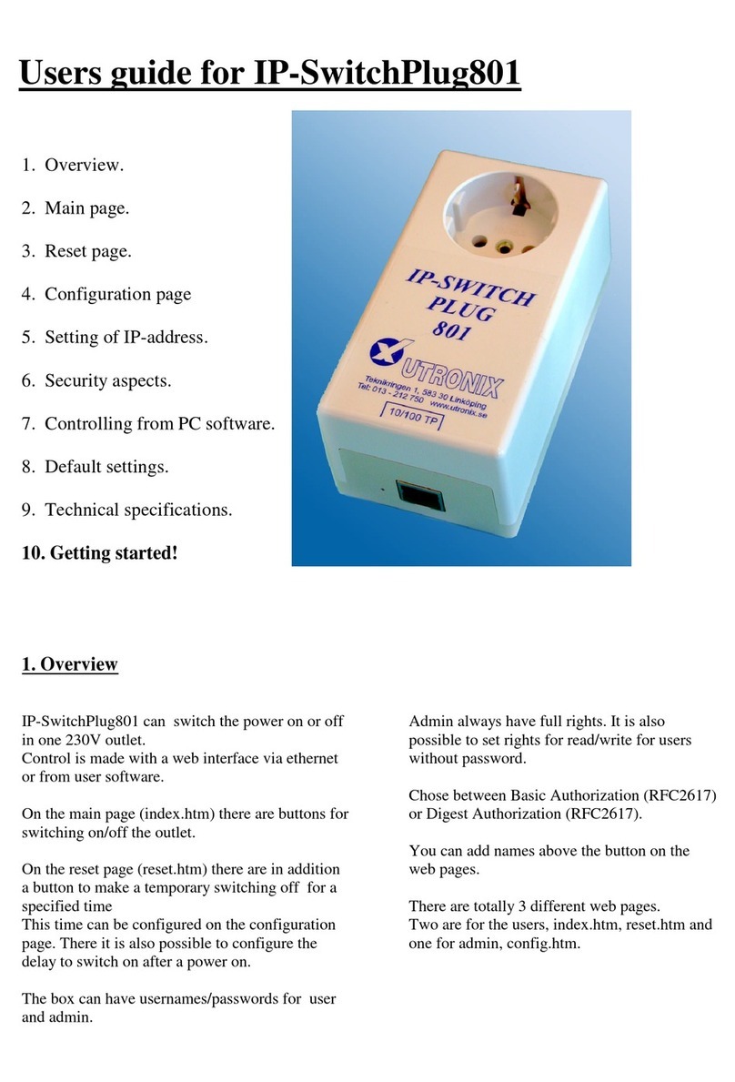
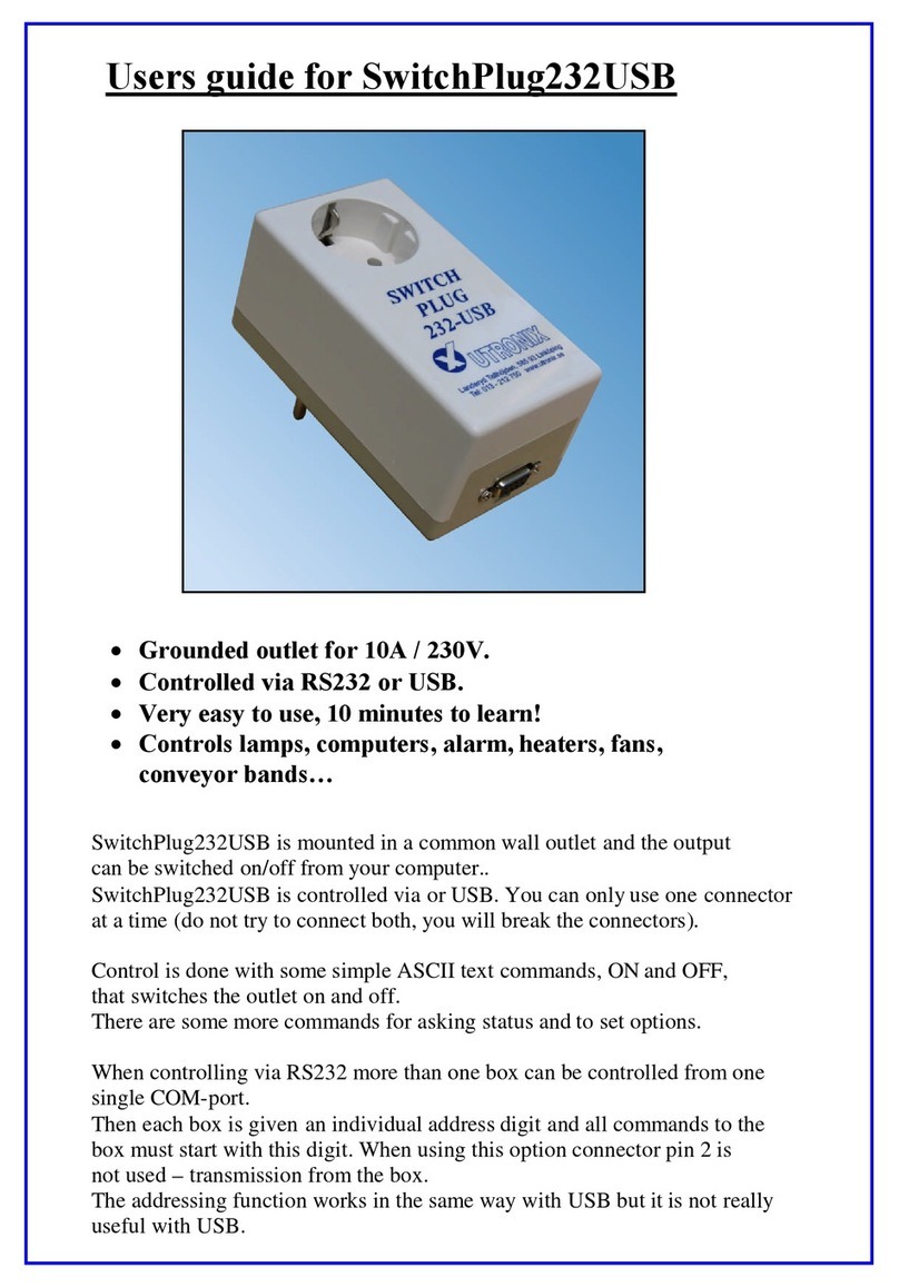
Utronix IP-SwitchBox902 User manual

Users guide for IP-SwitchBox902
1. Overview
2. Main page.
3. Reset page.
4. Telnet -RS232 page.
5. Configuration pages.
5.1 Config main.
5.2 Switches.
5.3 User manager.
5.4 Access rights.
6. The RS232 port.
6.1 Remote control via telnet.
6.2 Control via RS232.
6.3 Configuring via RS232.
7. Many simultaneous users.
8. Safety aspects.
9. Control from user program.
10. Default values.
11. Technical specifications.
12. Get started, fast!
1. Overview
IP-SwitchBox902 can switch 16 relays on or off.
Control is made with a web interface via ethernet
or with simple ASCII text commands via RS232.
It is also possible to control the RS232 port via
Telnet.
On the main page (index.htm) there are buttons for
switching on/off the outputs.
On the reset page (reset.htm) there are in addition
buttons to make a temporary switching off for a
specified time.
This time can be configured for each output.
At power on the outputs are switched on after a
delay. This delay can be configured for each
output, from 0s up to 600s.
In this way connected equipment can be started in
sequence after power failure.
The Box can have usernames/passwords for 8
users + admin + telnet.
Each user can have individual access rights for
each output. The rights can be read, write or no.
Admin always has full rights except for telnet.
It is also possible to configure read/write rights for
users without passwords.
You can add names above the buttons on the web
pages and at the top of the web pages.
The box can be reserved for one single user at a
time. When that user not has accessed the box
during the configured time any other user can
access it.

There are totally 8 different web pages.
Three are for the users, index.htm, reset.htm and rs232
The remaining five pages are for configuration of the box and is reached only by admin, they are:
config.htm: For configuration of IP address, port number, title at the user pages, basic or digest
authorization, and the time the box is reserved for one user.
switches.htm: Here the names of the 8 ON/OFF buttons and the delays at power on and the reset delays
is configured.
users.htm: Here is usernames and passwords for the 8 users + admin and Telnet is configured.
rights.htm: Here access rights are configured for all user 1 to 3 and for those not logged in.
r2.htm: Here access rights are configured for users 4 to 8.
2. The main page.
The main page (index.htm) is used to switch the outputs ON/OFF..
When you click at the ON or OFF button a
request for this is sent to the box.
Then the button turns gray until the box has
confirmed the change. When the confirmation
arrives the button indicates current setting again.
In this way you can be sure that the change
request actually has reached the box and been
serviced.
If you click at "refresh screen" then a question
about current status is sent to the box. The
buttons turns gray until the reply is received. This
is particular useful when many user control the
box.
In some cases you might like to switch more
than one output at exactly the same time. The
you untick the box "update box on change".
The nothing is sent to the box until you click
the button "update box".
The digits 1 to 16 above the ON/OFF buttons
may be replace by your own text. This is done
at the configuration page switches.htm.
A title at top of the page can be configured at
the page config.htm.
These changes can only be done after you have
logged in as admin, as described in the
configuration part below.

3. The reset page.
The reset page (reset.htm) has in addition to the ON/OFF buttons also reset buttons for the outputs in
position ON.
On output 5 a reset is started. The Reset can be cancelled by clicking "Turn ON" or "Turn OFF".
By clicking a reset button the output is switched
OFF during a configured time (up to 600s). After
that time it is automatically switched ON again.
The switch off time is controlled by IP-SwitchBox
902 and is hence not dependent of any delays on the
internet.
The time is configured at the configuration page
switches.htm.
These changes can only be done after you have
logged in as admin, as described in the
configuration part below.
During the reset time the "ON" and "Reset"
buttons is replaced by two buttons that can
cancel the reset, "Turn ON" and "Turn OFF".
During the rest time the browser contacts the
IP-Switchbox902 with some seconds interval
and updates the buttons. So after the reset
time the web page is updated and the "ON"
and "Reset" buttons are restored.

4. The Telnet - RS232 page.
You can send and receive characters to/from the RS232 port with any Telnet client, for example Windows
HyperTerminal
This remote control may be used to control equipment remotely, for example as console to a computer,
UPS or other RS232 connected unit.
To be able to control the RS232 port first the telnet port must be configured to something else than 0.
If not, the RS232 port will be used for local control instead.
The Telenet connection gas is own username/password.
More than one user can be active simultaneously with this username.
This is the small Telnet client for the web browser.
At the page RS232.htm there are a small Telnet client. It is a Java applet that starts when you load the
page.
In this way you can send and receive text via the RS232 port of the box with your web browser.
This will only work with older web browsers.
New web browsers needs a Java plug in for this function to work. It also requires that your policy file for
java security is changed to allow more.
The policy file usually can found at a location like this:
”c:\program\java\j2re1.4.1_01\security\java.policy”. The information to add is "permission
java.lang.RuntimePermission "accessClassInPackage.sun.misc";"
Usually a easy way is to use an separate Telnet client software.

5. The configuration pages.
The configuration pages is at config.htm.
5.1 Config main
At config main you configure:
IP address, http port, telnet port, title on the user pages, basic/digest authorization, time to reserve the
box for a single user. The MAC address is also showed.
IP address, port number and title.
The IP address is written in common way with dots
between.
You can also change port number if you want other
port numbers than 80 for http and 23 for Telnet.
After changing IP address/port you have of course
to contact the box at the new IP address/port.
As title you can write text that you like to have at
the top of the user pages. In front of this text the
user name will be placed followed by @.
Without title the username will not be showed.
You can configure a title with a blank only to get
the username only at the top the pages.
RARP / BOOTP.
By setting the IP address to 0.0.0.0 the IP-address is
allocated by RARP. With 0.0.0.1 BOOTP are used.
With 0.0.0.2 both RARP and BOOT is tried.
You can configure access rights also for not logged
in at the "access rights" web page.
One user at a time.
By writing a time (greater than 0) at "lock time" you
prevent access from more than one user at a time.
The box is reserved for the user only for the
specified time after his last access.
Admin has higher priority and can always access
the box, this might lock a present user out.
The configuration is saved by clicking "apply
changes".Admin har dock högre prioritet och
kommer alltid åt boxen och kan därigenom även
spärra ut aktuell användare .
When you have made your chioces then click
"apply changes" to save them.

5.2 Switches
At this page you configure names above the buttons, delay of switch on, and reset times.
Above each ON/OFF button you can configure a text of maximum 32 characters.
With up to 7 characters the layout of the page will be unchanged.
Turn on delay" is used to delay switch on of the outputs for up to 10 minutes after power failure.
This is to activate the outputs in a sequence.
Reset delay" is used to specify the time that the outputs shall be switched of at reset sequences,
when clicking at the reset buttons at the web page "reset.htm".

Here names have been added above the buttons and a title is added at top of the page.
5.3 User manager
At this page you specify usernames and passwords for all 8 users and for admin and telnet.
The characters A-Z, a-z and 0-9 may be used.
By leaving it blank at one "Login" the number of users are reduced by one.
By leaving it blank at "Password" no password is required for that user.
The box is here configured for admin, telnet plus three users of whom one does not need password.

5.4 Access rights
At this page access rights for 3 users and for those not logged in are configured.
Admin always has full rights.
Here administrator has full rights and so has those not logged in.
Five more users can be configured on the page !…more users! (r2.htm).
Access rights is configured for each output.
Choose between:
no -no read or write rights. Corresponding button turns white.
r/o - read only. Present position is showed with slightly grayed ON/OFF buttons.
The outputs can not be changed.
r/w- read/write. Present position is showed with normal ON/OFF buttons. The outputs can be changed.
6. The RS232 port
The RS232 serial port can be used for three purposes:
1) Remote control of the RS232 port via inter/intranet. By Telnet or browser.
2) Local control of the outputs.
3) Configuring of IP-SwitchBox902.
The configuring mode can always be accessed immediately after power on (0,5s).
After that the port is used either for local control or for the remote control..
This has been selected in the configuration.

6.1 Remote control of the RS232 port
You can connect to the RS232 port of the box with Telnet.
This can be done with any Telnet client or with the browser at rs232.htm .
To be able to use the remote control a port number higher than 0 must have been configured for Telnet.
If port 0 is configured then the RS232 port is used for local control.
Usually port 23 is used for Telnet communication.
After approx 5 minutes of inactivity an internal timer automatically disconnects the Telnet connection.
6.2 Local control via RS232.
The IP-Switchbox is controlled by simple text (ASCII) commands via an RS232 port.
To be able to use the local control the portnumber for Telnet has to be configured to 0 (=Telnet not enabled).
Use a terminal or a computer with terminal program for the local controlling, for example Windows "Hyper
Terminal".
The communication parameters is 9600baud, 8 data bits, no parity, one stop bit, no handshake.
Connection to a PC is done with a "straight cable" (that is with pin 1 to pin 1, 2 to 2 etc).
The control commands are:
Switch on output x: ONxx example: ON01
Switch off output x: OFFxx example: OFF02
Make reset on output x: Rxx example: R03
Ask about present positions: ? The answer is, for example, 1110011011100110.
That is 1 for outputs switched ON and 0 for outputs switched off.
6.3 Configuration via RS232.
IP-Switchbox902 may be configured via RS232.
You find the configuration mode by keeping the key "c" down on keyboard at the same time as you switch on
the power (five "c" within the first 0,5 seconds).
A menu will then appear that shows some of the settings and a small menu for the other settings.
Welcome to the IP address configurator for IP-SwitchBox902
==========================================================
Version: 1.00 (Tue, 20 Apr 2004 20:10:52 GMT)
MAC = 00-50-C2-09-64-0D
IP = 10.195.70.218
PORT = 80
TELNET = 23
DIGEST = 0
LOCK = 60.00 seconds
To display settings, type:
"T" for names at web page.
"R" for reset times.
"S" for turn on delays.
"U" for user names.
"W" for passwords.
"A" for access rights.
"Z" for IP, Port number and MAC.
>

Change the setting by, for example, write:
MAC= The serial number and Ethernet address of the box. Can not be changed.
IP=10.195.70.218 The digits are replaced by the new IP address.
Port=80 The digits are changed to the new port number.
Telnet=23 Telnet access is done at port 23. 0=RS232 port is used for local control instead..
Digest=0 0=Basic authorization, 1=Digest authorization
Lock=60 The box is reserved for the user during 60 seconds after last access..
Other users can read the box all the time though.
T0 =Title Write the title to be placed at the top of the web pages.
T1=Output1 Write the text to be placed above the ON/OFF button 1.
T2=Output2 Write the text to be placed above the ON/OFF button 2. etc
The output can have text labels with up to 32 characters. Long names will change the layout of the web page.
U1=User1 Write the username for user 1. etc. Use U0 for admin.
W1=Password1 Write the password for user 1. etc. Use W0 for admin.
R1=10 Specify reset time for output 1 in seconds. etc
S1=0,2 Specify delay for output 1 at power on. etc
A=wwrrnnnnr Specify the access rights for up to 8 users + those not logged in (ninth
user). w = read and write rights, r= read rights, n= no rights.
Z Prints the start menu as above again. Good for checking the settings.
Write one of T,U,W,R,S,A,Z followed by <CR> to print the settings on the screen.
All those command shall be ended with <CR>.
The configuration mode must be quited with "q" to leave the configuration mode.
You have to leave the configuration mode to control the box in normal way again.
7. More than one user at a time.
More than one user can control the IP-Switchbox902 at the same time.
This may be confusing, especially if the reset function is used. If one user operates an output while
it's doing a reset the reset function will be cancelled and the output will be in the requested position.
To avoid complications with two or more users interfere with each other there are a setting in the
configuration for the minimum time that must pass after one user has operated the box until another
user can operate it. See 5.1 "Lock" above.
The remote control of the RS232 port via Telnet can always be accessed by many users.
8. Security aspects.
--------

9. Controlling from your own software.
You can control the IP-SwitchBox from your own programs. Http is used.
There are two "commands" for this, k0 and k1.
Reading.
Send a http request for k0 to get current status.
The reply consists of 17 bytes in hexadecimal format:
Byte 1 …. 4 Tells the setting of the output for example." 4031" (0x34, 0x30, 0x33, 0x31) tells that outputs
1,5,6 and 15 are on. Positions without read rights are reported as off.
Byte 5 … 8 Tells which outputs that currently are doing reset.
Byte 9 …12 Tells the read rights. For example, 000F (0x30, 0x30, 0x30, 0x46) tells that you have read
rights on output 4, 3, 2 and 1.
Byte 13…16 Tells the write rights in the same way.
Byte 17 Is 0 (0x30) if the box is available for control and is 1 (0x31) if the box is reserved for another
user.
Example:
By sending "GET /k0" via http we get the answer "40310000FFFF100F0" that means;
That output 15, 6, 5 and 1 are on.
That no output is doing reset.
That we have read rights on all 16 outputs.
That we have write rights on output 16, 4, 3, 2 and 1.
That we may write to the box.
(If you write it in groups it is easyer to read: 4031 0000 FFFF 100F 1234 0)
Control.
To control the box a http request for k1aaaabbbbccccdddd is sent.
Where a,b,c,d are the parameters.
aaaa Bit mask for switch on. Four bytes of hexadecimal values (0..F).
A bit set to 1 means that the corresponding output shall be switched on. (for
example. "40F1" means that output 15, 8, 7, 6, 5 and 1 shall be on)
bbbb Bit mask for switch off. Four bytes of hexadecimal values (0..F).
A bit set to 1 means that the corresponding output shall be switched off.
The bit mask for switch on has higher priority than the bit mask for switch off.
If both the bit for switch on and switch off is set to 1 the output will be on.
cccc Bit mask for reset. Four bytes of hexadecimal values (0..F).
A bit set to 1 means that the corresponding output shall make a reset sequence.
dddd Bit mask for Four bytes of hexadecimal values (0..F).
canceling reset. A bit set to 1 means that the reset sequence for the corresponding output shall
be canceled.
The bit mask for cancel have higher priority than the bit mask for reset.
Example: By sending "GET /k140F1FFFF0000FFFF" via http:
We switch on output 15, 8, 7, 6, 5 and 1.
We switch off other outputs that might have been on before.
We do not start any reset sequence.
We cancel all current reset sequences.

One example in Perl on how to use those commands can be found at the demo CD in Unix\switchbox902.pl.
The outputs are there changed in sequence just to demonstrate it.
The code is meant to be changed by the user for other purposes.
The same can of course be done in other programming languages.
You have to change to current IP address for the box in the file switchbox902.pl to make the example work.
It is also possible to run the script in Windows environment by using, for example, ActivePerl.
On the CD there are also an example in Visual Basic.
10. Default settings.
IP address: 10.195.70.218
Port, http: 80
Port, telnet: 23
Title at web page: No title.
Authorization: Basic.
Lock time: 0
Name at buttons: 1,2,3,4,5,6,7,8,9,10,11,12,13,14,15,16
Turn on delay: 0/0,2/0,4/0,6/0,8/1,0/1,2/1,4/1,6/1,8/2,0/2,2/2,4/2,6/2,8/3,0s
Reset delay: 10s
Username/Password.
admin: root/root_pwd Change this to prevent unauthorized use.
user1-8: 1/2/3/4/5/6/7/8 No Usernames/Passwords.
Access rights:
user1-8: No access rights.
unauthorized: Full rights on all outputs.

11. Technical specifications.
Power supply:
Connection: From any of the -48V terminals on the rear side
Current consumption: Between 10mA and 400mA depending on number of active relays.
Connection of the relays, as seen from the rear side:
There are 16 similar groups of 3 connections each, one group per relay.
The rightmost connector is for incoming –48V.
In the middle 0V ,ground, is connected.
To the left outgoing –48V is available.
The 0V connection is only used for powering the box.
It is sufficient with only one ground connection used.
Internally the 0V connections are connected with a 2,5mm2 copper cable.
Load current should not be drawn though the internal 0V.
That is if outgoing 0V is connected to the box then also an ingoing 0V has to be
connected to the same connector.
The difference between in- and outgoing –48V is that the box gets its power supply from
the in-going –48V.
It is sufficient if –48V is available on one of the ingoing -48V connections to make the box work.
Max relay current: 15A *)
Max relay voltage: 48V *)
*) The relays themselves are specified 30A 400VAC/70VDC.
The internal connections are made with 2,5mm2 copper.
Signal connections.
RS232.
9-pol D-sub connector with sockets.
Data in at socket 3. Data out at socket 2. Signal ground at socket 5.
A common straight cable may be used for connection to PC.
9600 Baud, 8 data bits, no parity, one stop bit, no handshake.
Ethernet.
10/100M TP
Straight cable is used for connection to hub.
Crossed cable is used for connection to PC.
Red control lamp: Lit at full duplex.
Green control lamp: Normally on. Momentary off at communication (100ms).
Yellow control lamp: Lit at 100Mbit connection.
Dimensions:
Width: 482mm
Depth: 283mm exkl. connectors and handles.
Height: 88mm.
Weight: 5,2kg

12 Getting started! Quick start for control via web interface!
a) Configure the IP address.
To get contact with the box via ether/internet you first have to configure a suitable IP address.
The IP address you get from your ether/internet administrator.
The IP address configuration is done via RS232.*)
For that you need, for example, a PC with terminal program like Windows Hyper terminal.
Configure: right COM port, 9600baud, 8 data bits, no parity,
1 stop bit, no handshake.
Connect the IP-SwitchBox902 with a straight (connection pin 1 to 1, 2 to 2etc) 9-pole serial
cable to the computer.
(to the same port as the terminal is configured to!). Use for example the supplied cable.
(It is now possible to control the box from the terminal with "ON1", "ON2", "OFF1" etc.)
Keep the key "c" down at the same time as you switch on the power to IP-Switchbox902.
Then a setup menu is printed that shows current settings.
Type the IP address like this; IP=10.195.70.218 and push return, the digits shall of course be replaced
by desired IP address. The box answers with the new address.
It is necessary to leave the setup menu by pushing "q" (like quit) to control the box in normal way.
b) Connect IP-SwitchBox902 to the network.
The supplied blue cable is a "straight" cable that is used for connection to hubs, the most common
connection.
If you like to connect directly to the computers network card then you need a "crossed" cable.
They often have red connectors.
c) Start the browser.
Type the address, for example, http://10.195.70.218 (replace the digits with the configured IP address).
Now the browser shall display the main page with the control buttons and you can control the box.
Common control is made from the default page /index.htm.
Control with reset is made from /reset.htm.
Remote control of the RS232 port is made from /rs232.htm.
Configuring is made from /config.htm. Then you have to log in as admin.
Default admin username is "root" password is "root_pwd".
This password should immediately be replaced to unique password for security reasons.
*) It is possible to change IP address from the web pages too. Then you have to have a network from where
you can reach the default IP address of the box: 10.195.70.218.
UTRONIX Elektronikutveckling AB Telephone: +46 13 212 750
Landeryd Tallhöjden, 585 93 Linköping Telefax: +46 13 212 725
Sweden e-mail:[email protected]
web: www.utronix.se
4.02 131009
Table of contents
Other Utronix Switch manuals
Popular Switch manuals by other brands

HP
HP Aruba 8360-48Y6C v2 Disassembly instructions

Eaton
Eaton xComfort CTAA-02/02 Assembly instructions

Edge-Core
Edge-Core ECS4510 Series installation guide

Diamond
Diamond Epsilon-12G2 user manual

SMC Networks
SMC Networks SMC TigerStack 1000 SMC8724ML3 Technical specifications

Cisco
Cisco Catalyst IE3400 Heavy Duty Series installation guide