manuals.online logo
Brands
  1. Home
  2. •
  3. Brands
  4. •
  5. HP
  6. •
  7. Switch
  8. •
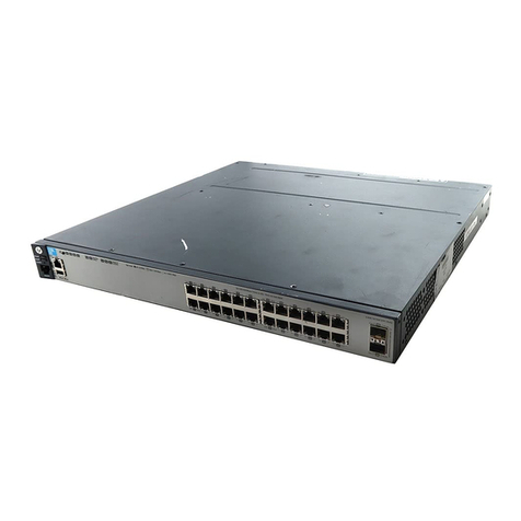
  9. HP Aruba 8360-48Y6C v2 Installation instructions

HP Aruba 8360-48Y6C v2 Installation instructions

This manual suits for next models

1

Other HP Switch manuals

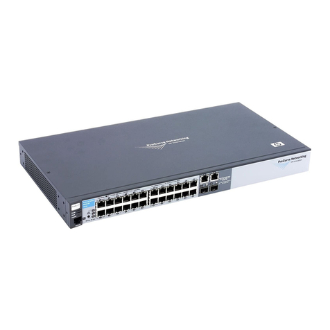
HP A5120 Series Instruction Manual

HP

HP A5120 Series Instruction Manual

HP ProCurve 6120G/XG User manual

HP

HP ProCurve 6120G/XG User manual

HP ProCurve 5400zl Series User manual

HP

HP ProCurve 5400zl Series User manual

HP B-Series User instructions

HP

HP B-Series User instructions

HP SN8000D User manual

HP

HP SN8000D User manual

HP J4902A User manual

HP

HP J4902A User manual

HP ProCurve 8206zl User manual

HP

HP ProCurve 8206zl User manual

HP Cisco MDS 9216 - Fabric Switch User manual

HP

HP Cisco MDS 9216 - Fabric Switch User manual

HP A7533A - Brocade 4Gb SAN Switch Base Instruction Manual

HP

HP A7533A - Brocade 4Gb SAN Switch Base Instruction Manual

HP J4900B User manual

HP

HP J4900B User manual

HP ProCurve Switch 1800-24G User manual

HP

HP ProCurve Switch 1800-24G User manual

HP 316095-B21 - StorageWorks Edge Switch 2/24 User manual

HP

HP 316095-B21 - StorageWorks Edge Switch 2/24 User manual

HP FlexFabric 5930 Series Installation manual

HP

HP FlexFabric 5930 Series Installation manual

HP ProCurve 5304xl User manual

HP

HP ProCurve 5304xl User manual

HP 10500 series User manual

HP

HP 10500 series User manual

HP FlexFabric 12900E series Installation manual

HP

HP FlexFabric 12900E series Installation manual

HP 1420 Series User manual

HP

HP 1420 Series User manual

HP 6400cl User manual

HP

HP 6400cl User manual

HP ProCurve 6120G/XG User manual

HP

HP ProCurve 6120G/XG User manual

HP 5400R zl2 Series User manual

HP

HP 5400R zl2 Series User manual

HP ProCurve 5300xl Programming manual

HP

HP ProCurve 5300xl Programming manual

HP HP ProCurve Series 6600 User manual

HP

HP HP ProCurve Series 6600 User manual

HP OfficeConnect 1850 6XGT 2XGT/SFP User manual

HP

HP OfficeConnect 1850 6XGT 2XGT/SFP User manual

HP StorageWorks T5527A User manual

HP

HP StorageWorks T5527A User manual

Popular Switch manuals by other brands

SMC Networks SMC6224M Technical specifications

SMC Networks

SMC Networks SMC6224M Technical specifications

Aeotec ZWA003-S operating manual

Aeotec

Aeotec ZWA003-S operating manual

TRENDnet TK-209i Quick installation guide

TRENDnet

TRENDnet TK-209i Quick installation guide

Planet FGSW-2022VHP user manual

Planet

Planet FGSW-2022VHP user manual

Avocent AutoView 2000  AV2000BC AV2000BC Installer/user guide

Avocent

Avocent AutoView 2000 AV2000BC AV2000BC Installer/user guide

Moxa Technologies PT-7728 Series user manual

Moxa Technologies

Moxa Technologies PT-7728 Series user manual

Intos Electronic inLine 35392I operating instructions

Intos Electronic

Intos Electronic inLine 35392I operating instructions

Cisco Catalyst 3560-X-24T Technical specifications

Cisco

Cisco Catalyst 3560-X-24T Technical specifications

Asante IntraCore IC3648 Specifications

Asante

Asante IntraCore IC3648 Specifications

Siemens SIRIUS 3SE7310-1AE Series Original operating instructions

Siemens

Siemens SIRIUS 3SE7310-1AE Series Original operating instructions

Edge-Core DCS520 quick start guide

Edge-Core

Edge-Core DCS520 quick start guide

RGBLE S00203 user manual

RGBLE

RGBLE S00203 user manual

Thrustmaster FLIGHT SIMULATOR X quick guide

Thrustmaster

Thrustmaster FLIGHT SIMULATOR X quick guide

Southwire SURGE GUARD 41390 RVC troubleshooting guide

Southwire

Southwire SURGE GUARD 41390 RVC troubleshooting guide

Buhler Nivotemp NT 61 Brief instructions

Buhler

Buhler Nivotemp NT 61 Brief instructions

Kramer VS-41HDCP user manual

Kramer

Kramer VS-41HDCP user manual

Techly IDATA AU-270 user manual

Techly

Techly IDATA AU-270 user manual

Belkin F1U109 user manual

Belkin

Belkin F1U109 user manual

manuals.online logo
manuals.online logoBrands
  • About & Mission
  • Contact us
  • Privacy Policy
  • Terms and Conditions

Copyright 2025 Manuals.Online. All Rights Reserved.

MF877-00 Page 1
Template Revision C, 30-July-2018
Copyright 2018 Hewlett Packard Enterprise Development LP
HPE instructions for this template are available at MF877-01
Product End-of-Life Disassembly Instructions
Product Category: Networking
Marketing Name / Model
[List multiple models if applicable.]
HPE Aruba 8360-48Y6C v2 Switch (JL719C)
Purpose: The document is intended for use by end-of-life recyclers or treatment facilities. It provides the basic instructions
for the disassembly of HPE products to remove components and materials requiring selective treatment, as defined by
Directive 2012/19/EU of the European Parliament and of the Council on Waste Electrical and Electronic Equipment
(WEEE).
1.0 Items Requiring Selective Treatment
1.1 Items listed below are classified as requiring selective treatment.
1.2 Enter the quantity of items contained within the product which require selective treatment in the right column, as
applicable.
Item Description
Notes
Quantity
of items
included
in product
Printed Circuit Boards (PCB) or Printed Circuit
Assemblies (PCA)
With a surface greater than 10 sq cm
4
Batteries
All types including standard alkaline and lithium
coin or button style batteries
1
Mercury-containing components
For example, mercury in lamps, display backlights,
scanner lamps, switches, batteries
0
Liquid Crystal Displays (LCD) with a surface
greater than 100 sq cm
Includes background illuminated displays with gas
discharge lamps
0
Cathode Ray Tubes (CRT)
0
Capacitors / condensers (Containing PCB/PCT)
0
Electrolytic Capacitors / Condensers measuring
greater than 2.5 cm in diameter or height
0
External electrical cables and cords
0
Gas Discharge Lamps
0
Plastics containing Brominated Flame Retardants
weighing > 25 grams (not including PCBs or PCAs
already listed as a separate item above)
0
MF877-00 Page 2
Template Revision C, 30-July-2018
Copyright 2018 Hewlett Packard Enterprise Development LP
HPE instructions for this template are available at MF877-01
Item Description
Notes
Quantity
of items
included
in product
Components and parts containing toner and ink,
including liquids, semi-liquids (gel/paste) and toner
Include the cartridges, print heads, tubes, vent
chambers, and service stations.
0
Components and waste containing asbestos
0
Components, parts and materials containing
refractory ceramic fibers
0
Components, parts and materials containing
radioactive substances
0
2.0 Tools Required
List the type and size of the tools that would typically be used to disassemble the product to a point where components
and materials requiring selective treatment can be removed.
Tool Description
Tool Size (if
applicable)
Torx Screw Drivers
T-10, T-15
Wire snips
Needle nose pliers
3.0 Product Disassembly Process
3.1 List the basic steps that should typically be followed to remove components and materials requiring selective treatment:
1. Unscrew the screws (qty 18) with a T-10 driver, from the top of the chassis (Figure 1)
2. Unscrew the screws (qty 3) with a T-10 driver, from the right side of the chassis (Figure 1)
3. Unscrew the screws (qty 3) with a T-10 driver, from the left side of the chassis (Figure 1)
4. Remove the lid from the chassis base
5. Remove the plastic tab fr chassis (Figure 2)
6. Remove the coin battery from its holder on the right side of the main PCA (Figure 3)
7. Cut cable tie with wire snips, remove the screw (qty 1) with a T-10 driver, from the PCA at the rear right corner of the
switch (Figure 4)
8. Disconnect the cable and remove the PCA (Figure 4)
9. Unscrew the screw (qty 1) with a T-10 driver, and the bracket that were under the rear PCA (Figure 5)
10. Unscrew the screw (qty 2) with a T-10 driver, and remove front PCA (Figure 6)
11. Use force to pull out the flex cable fr the 2 connector (Figure 7)
12. Unscrew the screw (qty 1) with a T-10 driver, from the front left chassis, and remove the shield cover and shield (Figure
8)
13. Unscrew the screws (qty 6) with a T-10 driver, that secure the daughter PCA to the base (Figure 9)
14. Remove the sheet metal parts that is securing the daughter PCA, remove the daughter PCA and then remove the 2
plastic airflow baffle (Figure 10)
15. Remove the DIMM PCA from the daughter PCA (Figure 11)
16. Remove the small heatsink by unclipping the two wire bails from the daughter PCA, then twist and untwist a couple of
times to remove the heatsink from the thermal interface material (Figure 12)
17. Unscrew the screws (qty 2) at the side, with a T-10 driver, and remove the left and right air baffle (Figure 13)
MF877-00 Page 3
Template Revision C, 30-July-2018
Copyright 2018 Hewlett Packard Enterprise Development LP
HPE instructions for this template are available at MF877-01
18. Unscrew the screws (qty 14) with a T-10 driver, that secure the main PCA to the base (Figure 14)
19. Remove the main PCA from the base. Remove the small heatsink by unclipping the two wire bails from the main PCA,
then twist and untwist a couple of times to remove the heatsink from the thermal interface material and unscrew the 8
screws fr the heatsink and remove the heatsink by twisting and untwisting a couple of times. (Figure 15)
20. At the front right corner of the main PCA, remove the front plastic lightpiple (Figure 16)
21. On the empty chassis front right, remove the 2 lightpipe (Figure 17).
3.2 Optional Graphic. If the disassembly process is complex, insert a graphic illustration below to identify the items
contained in the product that require selective treatment (with descriptions and arrows identifying locations).
Figure 1: Chassis screw locations
MF877-00 Page 4
Template Revision C, 30-July-2018
Copyright 2018 Hewlett Packard Enterprise Development LP
HPE instructions for this template are available at MF877-01
Figure 2: Plastic tab location
Figure 4: Rear PCA fastener and
connector
Figure 5: Rear PCA bracket and fastener
Figure 3: Coin battery location
Figure 6: Front PCA and fastener
MF877-00 Page 5
Template Revision C, 30-July-2018
Copyright 2018 Hewlett Packard Enterprise Development LP
HPE instructions for this template are available at MF877-01
\
Figure 7: Flex cable
Figure 8: Shield assembly
Figure 9: Daughter PCA screw location
MF877-00 Page 6
Template Revision C, 30-July-2018
Copyright 2018 Hewlett Packard Enterprise Development LP
HPE instructions for this template are available at MF877-01
Figure 10: Daughter PCA removal
Figure 8: ASIC stacked fin heatsink hardware assemblies
Figure 11: Flex cable
Figure 12: Shield assembly
MF877-00 Page 7
Template Revision C, 30-July-2018
Copyright 2018 Hewlett Packard Enterprise Development LP
HPE instructions for this template are available at MF877-01
Figure 13: Left and right air baffle
reval
MF877-00 Page 8
Template Revision C, 30-July-2018
Copyright 2018 Hewlett Packard Enterprise Development LP
HPE instructions for this template are available at MF877-01
Figure 14: Main PCA screw location
MF877-00 Page 9
Template Revision C, 30-July-2018
Copyright 2018 Hewlett Packard Enterprise Development LP
HPE instructions for this template are available at MF877-01
\
Figure 15: Main PCA and heatsink removal
Figure 16: Light pipe Removal
Figure 17: Front light pipe removal