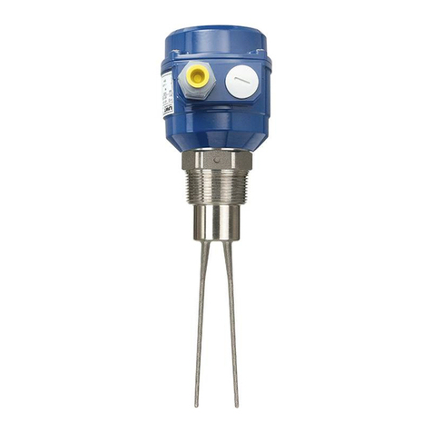
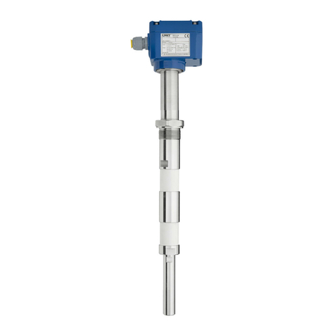
UWT Capanivo CN 7000 Series User manual

Capanivo®1
2
3
4
5
6
7
8
9
10
11
12
CN 7000 gi240621 1
Level limit switch
Series CN 7000 - IO-Link/ PNP/ NPN
Technical Information / Instruction manual
page
Table of contents
Subject to technical change. We assume no liability for typing errors.
Different variations than specied are possible.
Please contact our technical consultants.
Page
Safety notes / Technical support 2
-----------------------------------------------------------------------------------------------------
Introduction 3
-----------------------------------------------------------------------------------------------------
Technical data Electrical data 4
Dimensions 6
Mechanical data 9
-----------------------------------------------------------------------------------------------------
Options/ Accessories 11
-----------------------------------------------------------------------------------------------------
Operating conditions 12
-----------------------------------------------------------------------------------------------------
Approvals 14
-----------------------------------------------------------------------------------------------------
Installation Mechanical installation 15
Electrical installation 20
-----------------------------------------------------------------------------------------------------
Operation Operating elemens / LED's 24
Operation with potentiometer 25
Factory calibration 26
Recalibration 27
Advanced calibration 28
Operation with IO-Link 33
IO-Link data / registers 34
Setting of signal outputs 36
Calibration possibilities 37
Factory calibration 38
Recalibration 39
Advanced calibration 40
-----------------------------------------------------------------------------------------------------
Troubeshooting 46
-----------------------------------------------------------------------------------------------------
Transport and Storage 47
-----------------------------------------------------------------------------------------------------
Maintenance 48
-----------------------------------------------------------------------------------------------------
Disposal 49

Capanivo®
1
2
3
4
5
6
7
8
9
10
11
12
CN 7000
gi240621
2
Level limit switch
Series CN 7000 - IO-Link/ PNP/ NPN
Technical Information / Instruction manual
page
Safety notes / Technical support
Notes
• Installation, maintenance and commissioning may be accomplished only by qualied technical personnel.
• The product must be used only in the manner outlined in this instruction manual.
Special attention must be paid to warnings and notes as follows:
Safety symbols
In manual and on
product
Description
CAUTION: refer to accompanying documents (manual) for details.
Earth (ground) Terminal
Protective Conductor Terminal
Technical support
Please contact your local supplier (for address see www.uwt.de). Otherwise you can contact:
UWT GmbH Tel.: 0049 (0)831 57123-0
Westendstr. 5 Fax: 0049 (0)831 76879
Germany www.uwtgroup.com
WARNING
Relates to a caution symbol on the product: A failure to observe the necessary
precautions can result in death, serious injury and/ or considerable material damage.
WARNING
Relates to a caution symbol on the product: Risk of electric shock
WARNING
A failure to observe the necessary precautions can result in death, serious injury
and/or considerable material damage.
This symbol is used, when there is no corresponding caution symbol on the product.
CAUTION A failure to observe the necessary precautions can result in considerable material
damage.

Capanivo®1
2
3
4
5
6
7
8
9
10
11
12
CN 7000 gi240621 3
Level limit switch
Series CN 7000 - IO-Link/ PNP/ NPN
Technical Information / Instruction manual
page
Introduction
The Capanivo series CN 7000 is a capacitance switch for:
• Level detection of liquids, solids (powder and granules), slurries and foam.
• Interface detection (for example, oil / water or foam / liquid)
It works in all types of vessels, pipes and silos within a wide range of appliations like:
• Food, brewery, dairy, beverage and pharmaceuticals
• Chemical and petrochemical
• Water and waste water
• Machine building industry
It can also be used for leckage detection in double walled vessels, tanks and silos or in
moldings and collecting ponds.
Applications
Measurement
principle
The Capanivo series CN 7000 detects the capacitance around its probe. Due to the active
shield technology it has an increased insensitivity to material buildup on the probe.
Features
Process • Measurement independent from inuence of the vessel wall
• Factory provided precalibration allows measurement of most applications without
sensitivity setting on site
• Active shield electrode for compensation of material buildup
• Potted construction protects from shock, vibration, humidity, condensation
• Dielectric constant of 1.5 or more
• Process temperature up to 125°C
• Approvals CE, FM, FMc, WHG
Electronics • IO-Link, IEC 61131-9 SDCI standard
• PNP, NPN or Push-Pull output (congurable)
• Terminal or M12 plug
• Sensitivity setting by IO-Link or by potentiometer (congurable)
Mechanics • Corrosion resistant construction with enclosure made of thermoplastic polyester,
wetted parts made of PPS, PVDF, PEEK and 316L stainless steel
• Compact probe lenght
• Pipe extension (max. 4m), optional sliding sleeve allows to change the switch point
easily during operation of the device
• Various process connections: threaded (including G½“ hygienic), anged (screwed)
or Tri-clamp

Capanivo®
1
2
3
4
5
6
7
8
9
10
11
12
CN 7000
gi240621
4
Level limit switch
Series CN 7000 - IO-Link/ PNP/ NPN
Technical Information / Instruction manual
page
Technical data
Electrical data
Power supply 10 - 30 V DC incl. 10% of EN 61010-1
Operation with IO-Link requires min. 18V
Current consumption: <55mA
Signal outputs
Electrical ratings
Out 1 and Out 2:
Max. current: One output active: 200 mA
Both outputs active: 100 mA each
(short-circuit proof)
Voltage drop: <2V
Out 1
Conguration
SIO mode*:
Factory setting PNP (FSL)
Other than factory setting can be congured via IO-Link as follows:
PNP (FSH) or
NPN (FSH or FSL) or
Push/pull (FSH or FSL)
COM-mode IO-Link communication
*Note: If there is no IO-Link communication, the device operates in the SIO mode
Out 2
Conguration
Factory setting PNP (FSH)
Note: Out 2 PNP is opposite to Out 1 PNP (antivalent)
Other than factory setting can be congured via IO-Link as follows:
PNP (FSL) or
NPN (FSH or FSL) or
Push/pull (FSH or FSL)
Diagnostics Self diagnostics present
Safety operation
(FSL,FSH)
Congurable via IO-Link
Signal delay Congurable via IO-Link. Factory setting
Probe uncovered -> covered ca. 0.5 sec
Probe covered -> uncovered ca. 0.5 sec
Indicating light Build in LEDs:
Power (green), Signal output (yellow), Sensor status / Diagnostics (white)
Sensitivity Factory setting Adjustable by potentiometer
alternative Programmable by IO-Link
Electrical connection With enclosure Ø65mm:
Terminal block, terminals (0.14 - 1.5 mm2 (AWG 28-16)
With enclosure Ø65mm and Ø35mm:
M12x1 according to IEC 61076-2-101, male, 4-pole, coding A-standard
Cable entry With enclosure Ø65mm:
M20 x 1.5 screwed cable gland
Clamping range (diameter) of factory provided cable glands: 6..12 mm (0.24 .. 0.47")
or
NPT 1/2“ conduit
Overvoltage category II
Protection class III

Capanivo®1
2
3
4
5
6
7
8
9
10
11
12
CN 7000 gi240621 5
Level limit switch
Series CN 7000 - IO-Link/ PNP/ NPN
Technical Information / Instruction manual
page
Technical data
Dimensions
CN 7120 - Short extension length
Enclosure
Ø65mm
Top view
G 1/2" hygienic
All dimensions in mm (inch)
G 1/2" hygienic
Top view
Stainless steel process connection
Top view
Top view
Enclosure
Ø35mm
Enclosure
Ø35mm
Enclosure
Ø65mm
see
next
page
see
next
page
CN 7121 - Short extension length
see next
page
G 1/2" G 3/4" G 1"
NPT 3/4"
G 1/2" G 3/4" G 1"
NPT 3/4"
1.4404 (316L)
Probe
PEEK
1.4404 (316L)
Probe
PPS/PVDF
1.4404 (316L)
Probe
PEEK
1.4404 (316L)
Probe
PPS/PVDF
PPS/PVDF
Plastic process connection
Probe
PPS/PVDF
Probe
PPS/PVDF
PPS/PVDF

Capanivo®
1
2
3
4
5
6
7
8
9
10
11
12
CN 7000
gi240621
6
Level limit switch
Series CN 7000 - IO-Link/ PNP/ NPN
Technical Information / Instruction manual
page
Technical data
CN 7130 - Pipe extension
CN 7130
1.4404
(316L)
1/2" NPT
conduit
M20x1,5
cable gland
M12
plug
Top view
see
below
Enclosure
Ø65mm
Possible wiring
Probe
PPS/PVDF
1.4404 (316L)

Capanivo®1
2
3
4
5
6
7
8
9
10
11
12
CN 7000 gi240621 7
Level limit switch
Series CN 7000 - IO-Link/ PNP/ NPN
Technical Information / Instruction manual
page
Technical data
Tri-clamp
Flange is screwed to
process connection
To Top:
Enclosure Ø65mm: 131 (5.2)
Enclosure Ø35mm: 110 (4.3)
Tri-clamp ØD
DN 25 (1") 50,5 (1.99")
DN 40 (1 1/2")
DN 50 (2") 64 (2.52")
Flange
Type Facing
thickness
ASME 150 lbs
ASME 300 lbs 2 mm (0.08")
Raised face
Facing
thickness
Code Type Number
of holes
d2
mm (Inch)
Lk
mm (Inch)
D
mm (Inch)
T
thickness
mm (Inch)
ASME B16.5,
raised face
R1" 150 lbs 4 15,9 (0.63) 79,3 (3.12) 108,0 (4.25) 14,3 (0.56)
S1" 300 lbs 4 19,1 (0.75) 88,9 (3.5) 123,8 (4.87) 17,5 (0.69)
T1½" 150 lbs 4 15,9 (0.63) 98,6 (3.88) 127,0 (5.0) 17,5 (0.69)
U1½" 300 lbs 4 22,2 (0.87) 114,3 (4.5) 155,6 (6.13) 20,6 (0.81)
V 2" 150 lbs 4 19,1 (0.75) 120,7 (4.75) 152,4 (6.01) 19,1 (0.75)
W2" 300 lbs 8 19,1 (0.75) 127,0 (5.0) 165,1 (6.5) 22,2 (0.87)
EN 1092-1
type A, at
faced
NDN25
PN16/40 4 14,0 (0.55) 85,0 (3.35) 115,0 (4.53) 18,0 (0.71)
P
DN40
PN16/40
4 18,0 (0.71) 110,0 (4.33) 150,0 (5.91) 18,0 (0.71)
QDN50
PN16/25/40 4 18,0 (0.71) 125,0 (4.92) 165,0 (6.5) 18,0 (0.71)

Capanivo®
1
2
3
4
5
6
7
8
9
10
11
12
CN 7000
gi240621
8
Level limit switch
Series CN 7000 - IO-Link/ PNP/ NPN
Technical Information / Instruction manual
page
Technical data
CN 7120 - G 1/2" hygienic process connection / EHEDG approval
Flush welding
socket:
Design Detail A:
Sealing area between CN 7120
(PEEK) and the on site process
connection (metal)
Metal type according to hygienic
and further external requirements.
CN 7120
process
connection
Metal
1.4404 (316L)
PEEK
FDA registration number:
21 CFR 177.2415
The ush welding socket must meet the following design:
see Detail A
Flush welding
socket:
Installation
Metal-peek sealing
• The support must be plane and without any
gap. No teon tape (or similar) is allowed to
be in between.
• Fixing torque 30 Nm
The quality of the welding with the
container wall must be according to
the respective regulations (e.g. gaps,
transitions, surface nish).
leackage
borehole
(optional)
EHEDG approval is available with CN7120 with process connection G 1/2" hygienic
EHEDG
versions

Capanivo®1
2
3
4
5
6
7
8
9
10
11
12
CN 7000 gi240621 9
Level limit switch
Series CN 7000 - IO-Link/ PNP/ NPN
Technical Information / Instruction manual
page
Mechanical data
Process connection
and extension
CN 7120 - Stainless steel process connection, version G 1/2" Hygienic:
Material process connection: 1.4404 (316L)
Material probe: PEEK (1,2)
Seal process connection-probe: FKM (optional FFKM) (2)
Thread (3): G 1/2" Hygienic
Wetted sensor surface: Ra ≤ 0.8 μm (31 μin)
Hygienic design: EHEDG
CN 7120 - Stainless steel process connection:
Material process connection: 1.4404 (316L)
Material probe: PPS (glass bre reinforced) (1,2)
Optional PVDF
(1,2)
Seal process connection-probe: FKM (optional FFKM) (2)
Thread (3): G 1/2", G 3/4", G 1“, NPT 3/4"
Adapters for G 1 1/2", NPT 1 1/4", NPT 1 1/2"
Tri-clamp DN25 (1"), DN40 (1 1/2"), DN50 (2")
DIN 32676 Type A (DIN 11851) and
DIN 32676 Type C (ASME BPE 2009)
Flange (screwed) (4) DN 25, 40, 50; ASME 1", 1 1/2”, 2"
CN 7121 -Plastic process connection:
Material process connection: PPS (glass bre reinforced) (1, 2)
Optional PVDF
(1,2)
Material probe: PPS (glass bre reinforced) (1,2)
Optional PVDF
(1,2)
Seal process connection-probe: FKM (optional FFKM) (2)
Thread (3): G 1“, NPT 3/4"
CN 7130 - Pipe extension:
Material process connection: 1.4404 (316L)
Material pipe extension: 1.4404 (316L)
Material probe: PPS (glass bre reinforced) (1,2)
Optional PVDF
(1,2)
Seal pipe-probe: FKM (optional FFKM) (2)
Thread (3): G 3/4", G 1“, NPT 3/4"
Adapters for G 1 1/2", NPT 1 1/4", NPT 1 1/2"
Flange (screwed) (4) DN 25, 40, 50; ASME 1", 1 1/2”, 2"
(1) Discolouration is possible due to inuence of UV and temperature. This has no negative
effect to the material properties.
(2) Food grade, FDA registration number:
Seals 21 CFR 177.2600
PVDF 21 CFR 177.1550
PPS 21 CFR 175.300
PEEK 21 CFR 177.2415
(3) Thread types: G = DIN ISO 228-1 NPT = ASME B 1.20.1
(4) Flange pressure rating: DN25 PN16/40, DN40 PN16/40, DN50 PN16/25/40
ASME 150lbs, ASME 300lbs
Technical data

Capanivo®
1
2
3
4
5
6
7
8
9
10
11
12
CN 7000
gi240621
10
Level limit switch
Series CN 7000 - IO-Link/ PNP/ NPN
Technical Information / Instruction manual
page
Technical data
Extension length "L" CN 7120 Stainless steel process conn.: 92 mm (3.6“)
CN 7121 Plastic process connection: 92 mm (3.6“)
CN 7130 Pipe extension: 300 .. 4000mm (11.8 .. 157")
Tolerance length "L“ CN 7120 Stainless steel process conn.: ±5 mm (±0.2“)
CN 7121 Plastic process connection: ±5 mm (±0.2“)
CN 7130 Pipe extension: ±10 mm (±0.4“)
Material
Enclosure Ø65mm
Material Housing: Thermoplastic polyester (PBT/PC)
Material Lid: Transparent thermoplastic polycarbonate (PC)
Material Seal between housing and lid: VMQ (vinyl-methyl-silicone)
Material Nameplate: polyester lm
Material
Enclosure Ø35mm
Material Housing: 1.4404 (316L)
Material Lid with M12 plug: Transparent thermoplastic polycarbonate (PC)
Material Seal between housing and lid: VMQ (vinyl-methyl-silicone)
Material Nameplate: polyester lm
Ingress protection Type 4X / IP68
Sound level n.a. (no sound is produced)
Overall weight (ca.) CN 7120 Stainless steel process conn.: 0.35 kg (0.77 lbs)
CN 7121 Plastic process connection: 0.25 kg (0.55 lbs)
CN 7130 Pipe extension: 0.6 kg (1.32 lbs) + 0.85 kg/m (1.87 lbs per 39.3“)
All weights with threaded process connection.

Capanivo®1
2
3
4
5
6
7
8
9
10
11
12
CN 7000 gi240621 11
Level limit switch
Series CN 7000 - IO-Link/ PNP/ NPN
Technical Information / Instruction manual
page
Options / Accessories
Sliding sleeve
CN 7130
G 1 1/4" / G 1 1/2" / NPT 1 1/4" / NPT 1 1/2"
Material: 1.4404 (316L)
Sealing material to the extension pipe: FKM
Max. process pressure: –1 to 10 bar (146 psi)
Options
Accessories
Adapter for process
connection
Adapter from G 1" thread to G 1 1/2"
Adapter from NPT 3/4 thread to NPT 1 1/4" / NPT 1 1/2"
Material: 1.4305 (303) or 1.4404 (316L)
Max. process pressure: –1 to 25 bar (363 psi)
Flush welding
socket
For version with EHEDG certicate
Fitting to CN 7120 with process connection G 1/2" hygienic
Flush welding socket ø30/ G 1/2", 1.4404 (316L),
with or without leackage borehole
Details see page 9
Shortening kit For CN 7150 extension cable
Sensguard Outer thread (process connection):
G1" DIN ISO 228-1 or NPT 3/4" ASME B 1.20.1
Internal thread:
G 1/2" (requires CN 7120 with process connection G 1/2" to t in).
Material: PPS
Max. process pressure: –1 to 10 bar (146 psi)
Complementary products (from outside companies)
M12 mating plug 4 pole, for version with M12 plug

Capanivo®
1
2
3
4
5
6
7
8
9
10
11
12
CN 7000
gi240621
12
Level limit switch
Series CN 7000 - IO-Link/ PNP/ NPN
Technical Information / Instruction manual
page
Ambient and
process
temperature
Mounting with long socket
Mounting with short socket
CN 7130
CN 7120
CN 7121
CN 7130
Derating of ambient
temperature with high
process temperature
Ambient- and process temperature limited to
-20°C (-4°F) with option FFKM seal O-ring
Ambient- and process temperature limited to
-20°C (-4°F) with option FFKM seal O-ring
Functional
Dielectric constant Min. 1.5
Factory setting = 2.0
For dielectric constant of applicable materials: see external dielectric constant tables
Switching point Depending on setting of potentiometer and dielectric constant value of measured material.
Repeatability 2 mm (0.08"), for water based liquids
Environment
Operating conditions

Capanivo®1
2
3
4
5
6
7
8
9
10
11
12
CN 7000 gi240621 13
Level limit switch
Series CN 7000 - IO-Link/ PNP/ NPN
Technical Information / Instruction manual
page
Operating conditions
Max. temperature
for CIP
135°C (275°F), duration 60min
150°C (302°F), duration 30min (only for CN 7120 with process connection G 1/2" hygienic)
Ambient temperature limited to 50°C (122°F), unit de-energized.
Max. permitted
mechanical torque
CN 7120 / CN 7121 CN 7130
Max. process pressure CN 7120 Stainless steel process connection: –1 to 25 bar (363 psi)
CN 7121 Plastic process connection: –1 to 10 bar (146 psi)
CN 7130 Pipe extension: –1 to 25 bar (363 psi)
CN 7130 Pipe extension with sliding sleeve: –1 to 10 bar (146 psi)
Observe possible pressure limitation from the used ange type !
Vibration 1.5 (m/s2)2/Hz according to EN 60068-2-64
Pollution degree 4
Relative Humidity 0 - 100%, suitable for outdoor use
Altitude max. 3.000 m (9.843 ft)
Ventilation Ventilation is not required
Expected product
lifetime
Following parameters have a negative inuence on the expected product lifetime:
High ambient- and process temperature, corrosive environment, high vibration, high ow
rate of abrassive bulk material passing the probe.
max. 80Nm
max. 400N
(at 40°C)
max. 400N
(at 40°C)

Capanivo®
1
2
3
4
5
6
7
8
9
10
11
12
CN 7000
gi240621
14
Level limit switch
Series CN 7000 - IO-Link/ PNP/ NPN
Technical Information / Instruction manual
page
General Purpose *
(Ordinary Locations)
CE
UKCA
FM / CSA
TR-CU
Overll and leackage
protection *, **
WHG
VLAREM
EMC EN 61326
RoHS conform According to directive 2011/65/EU
Food grade material Wetted parts with FDA registration. Details see "Mechanical data".
Pressure Equipment
Directive
(2014/68/EU)
The units are not subject to this directive, because they are classied as „pressure-
keeping equipment“ and do not have a pressurized housing (see Art.1, clause 2.1.4).
The units are designed and manufactured in accordance to the Pressure Equipment
Directive.
The unit is NOT intended for use as an “equipment part with safety function (Art.1, clause
2.1.3).
If the units should be used as „equipment part with safety function" please contact the
manufacturer.
* Depending on selected version
** Relevant information for use in applications with WHG/VLAREM: see documentation "Technical Description"
Approvals

Capanivo®1
2
3
4
5
6
7
8
9
10
11
12
CN 7000 gi240621 15
Level limit switch
Series CN 7000 - IO-Link/ PNP/ NPN
Technical Information / Instruction manual
page
Mechanical installation
General Safety Instructions
Process pressure Improper installation may result in loss of process pressure.
Observe possible pressure limitation from the used ange type or in case of use of the
sliding sleeve (CN 7130).
Chemical resistance
against the medium
Materials of construction are chosen based on their chemical compatibility (or inertness) for
general purposes. For exposure to specic environments, check with chemical compatibility
charts before installing.
Fastening of the
threaded process
connection
Mounting torque for the thread may not exceed 40 Nm (metal thread)/ 20 Nm (plastic
thread). Use a open-end wrench. Do not fasten by turning the housing, for this will destroy
the unit.
EHEDG approval/
Food grade material
The materials are available for the use under nornal and predictable applications (according
to directive 1935/2004 Art.3). Other conditions can inuence the safety.
General Mounting instructions
At the end of the
pipe before the
probe
Midway along
the pipe
At the process
connection or
ange
Handling
precautions
To prevent damage of the pipe extension, all CN 7130 units with a pipe longer than 2 m (6.5
ft), must be suppported at these three points when lifting from a horizontal position
Sliding sleeve Tighten both straining screws with 15 Nm to obtain
resistance against pressure
Direction of the
cable glands
(enclosure Ø65mm)
When the unit is mounted from the side, ensure, that the cable glands face downwards and
are closed to avoid water penetration into the housing.
The enclosure can be rotated against the process connection after mounting.
Sealing Ensure proper seal of the process connection thread in case of process pressure.
Hygienic process
connection
Observe that the correct "On site process connection" is present, see page 8.

Capanivo®
1
2
3
4
5
6
7
8
9
10
11
12
CN 7000
gi240621
16
Level limit switch
Series CN 7000 - IO-Link/ PNP/ NPN
Technical Information / Instruction manual
page
Liquid applications - Mounting instructions
Mechanical installation - Liquid applications
Vertical vessel
A Full detector horizontal
B Demand or empty detector horizontal
C Empty detector oblique from the bottom
D Empty detector in outlet pipe
CAUTION
Observe:
• General distances of the probe (see page 17)
• Distance to material ow (lling)
• Max. permitted mechanical load (see page 13)
CN 7120 /
CN 7121
Horizontal vessel
E Full detector vertical
F Demand or empty detector horizontal
G Empty detector vertical from the bottom
Horizontal pipe
H Full detector vertical
J Demand or empty detector horizontal
K Empty detector vertical from the bottom
Vertical pipe
L Full, demand or empty detector horizontal
Bypass
M Full detector horizontal
N Demand or empty detector horizontal

Capanivo®1
2
3
4
5
6
7
8
9
10
11
12
CN 7000 gi240621 17
Level limit switch
Series CN 7000 - IO-Link/ PNP/ NPN
Technical Information / Instruction manual
page
Mechanical installation - Liquid applications
CN 7130
Vertical vessel
Full, demand or empty detector:
A Vertical
B Vertical with sliding sleeve
C Vertical with long mounting socket
D Vertical from bottom
CAUTION
Observe:
• General distances of the probe (see page 17)
• Distance to material ow (lling)
• Max. permitted mechanical load (see page 13)
Horizontal vessel
E Full, demand or empty detector vertical
F Vertical with sliding sleeve
G Vertical with long mounting socket
Bypass
H Full, demand or empty detector vertical
Observe min. distance
• between two probes
• to metal vessel wall
Distances of the
probe
CORRECT
Probe leads
into the product
WRONG
Socket too
long
Observe socket length

Capanivo®
1
2
3
4
5
6
7
8
9
10
11
12
CN 7000
gi240621
18
Level limit switch
Series CN 7000 - IO-Link/ PNP/ NPN
Technical Information / Instruction manual
page
Mechanical installation - Solid applications
A Full detector horizontal or oblique.
Slight incline mounting helps remaining material to
fall off more easily.
B Demand or empty detector horizontal or oblique.
Slight incline mounting helps remaining material to
fall off more easily. Protective angle recommended
depending on load and abrasion of the material
C Empty detector oblique from the bottom
D Empty detector in the silo outlet
CN 7120 /
CN 7121
CN 7130
A Full detector vertical
B Full detector with sliding sleeve
C Full detector horizontal or oblique. Slight incline
mounting helps remaining material to fall off more
easily
D Demand or empty detector horizontal or oblique.
Slight incline mounting helps remaining material to
fall off more easily. Protective angle recommended
depending on load and abrasion of the material
CAUTION
Observe:
• General distances of the probe (see page 19)
• Distance to material ow (lling)
• Max. permitted mechanical load (see page 13)
• Wearing due to abrasive bulk material
CAUTION
Observe:
• General distances of the probe (see page 19)
• Distance to material ow (lling)
• Max. permitted mechanical load (see page 13)
• Wearing due to abrasive bulk material
Solid applications - Mounting instructions

Capanivo®1
2
3
4
5
6
7
8
9
10
11
12
CN 7000 gi240621 19
Level limit switch
Series CN 7000 - IO-Link/ PNP/ NPN
Technical Information / Instruction manual
page
Distances of
the probe
CORRECT
Probe leads
into the product
WRONG
Socket too
long
Oblique
mounting
Observe mounting angle to ensure, that
the active tip of the probe has enough
distance to the metal silo wall
Mechanical installation - Solid applications
Perpendicular
mounting
Observe socket length
Observe min. distance
• between two probe
• to metal vessel wall
• to protective angle
CORRECT
Probe leads
into the product
WRONG
Socket too
long

Capanivo®
1
2
3
4
5
6
7
8
9
10
11
12
CN 7000
gi240621
20
Level limit switch
Series CN 7000 - IO-Link/ PNP/ NPN
Technical Information / Instruction manual
page
Electrical installation
Handling In the case of inexpert handling or handling malpractice the electric safety of the device
cannot be guaranteed.
Installation
regulations
The local regulations or VDE 0100 (Regulations of German Electro technical Engineers) must
be observed.
Power supply switch A power-supply-disconnecting switch must be provided and marked near the device.
Wiring diagram The electrical connections have to be made according to the wiring diagram.
Supply voltage Compare the supply voltage applied with the specications given on the name plate before
switching the device on.
The unit must be supplied from a SELV source providing electrical isolation between the
input and output, in order to meet the applicable safety requirements of IEC 61010-1.
Observe reduced supply voltage ratings in wet locations. A wet location is a location where
water or other conductive liquid may be present and is likely to increase the risk of electric
shock.
Cable gland
and
Field wiring cables
With use of terminal block and cable gland:
The screwed cable gland must have following specications:
• Ingress protection IP68
• Temperature range from -40°C to 10 K above max. ambient temperature
• UL or VDE certied (depending on the country where the unit is installed)
• Pull relief
Make sure that the screwed cable gland safely seals the cable and that it is tight (danger of
water intrusion).
The eld wiring cables must have following specications:
• The diameter has to match to the clamping range of the used cable gland.
• The cross section has to match with the clamping range of the connection terminals and
consider the max. current.
• The temperature rating must be at least 10 K above max. ambient temperature.
Cut the eld wiring cables to appropriate length to t properly into the housing.
M12 mating plug
and
Field wiring cables
With use of M12 plug:
The mating plug must must have following specications
• M12x1 according to IEC 61076-2-101, female, 4-pole, coding A-standard
• Ingress protection IP68
• Temperature range from -40°C to 10 K above max. ambient temperature
The eld wiring cables must have following specications:
• The diameter and cross section has to match to the specication of the mating plug.
• The temperature rating must be at least 10 K above max. ambient temperature.
• Install the eld wiring cables according to the instructions of the mating plug
Signal output contact
protection
Provide protection for signal output to protect the device against spikes with inductive loads
(e.g. when connecting external relays).
Protection against
static charging
The unit must be earthed in any case to avoid static charging of the unit, especially on
applications with pneumatic conveying. Functional earthing is satisfactory to protect against
static charging, see page 21.
General Safety Instructions
Other manuals for Capanivo CN 7000 Series
1
This manual suits for next models
3
Table of contents
Other UWT Switch manuals

UWT
UWT Vibranivo VN 4000 Series User manual

UWT
UWT RFnivo RF 8000 Series User manual

UWT
UWT Vibranivo VN 1000 Series User manual

UWT
UWT RF 3000 Series User manual

UWT
UWT Rotonivo RN 4000 Series User manual

UWT
UWT Rotonivo RN 4000 Series User manual

UWT
UWT Capanivo CN 4000 Series User manual

UWT
UWT Vibranivo VN 1000 Series User manual

UWT
UWT Capanivo CN 4000 Series Instruction Manual

UWT
UWT RN 3000 Series User manual