Carefully inspect your new motorized storage unit for any possible damage and/or
shortage of parts. Separate all major components and parts as detailed below and on
the next page. Do not attempt installation if parts are damaged or missing. If parts of your
GGR125 are missing or appear damaged call V-Bro customer service at 1-888-GATOR-
08, Monday - Friday, 8:00 AM to 5:00 PM Eastern Time. Before calling carefully check the
carton as parts may be in the packing material.
5
CARTON INVENTORY tinUegarotSdezirotoMrotaGegaraG
(A) Motor Mounting Plate
MAJOR COMPONENTS
5
parts of your GG125 are missing or appear damaged call V-Bro customer service at
1-800-954-6745, Monday – Friday, 8:00 AM to 5:00 PM Eastern Time. Before calling
carefully check the carton as parts may be in the packing material.
MAJOR COMPONENTS
Motor Mounting Plate (A)
Motor Hoist (B)
Spacer Channel Bar (C) Spacer Channel Pulley Bar (D)
Hook Bar Connector x2 (F)
Hook Bar End x2 (G)
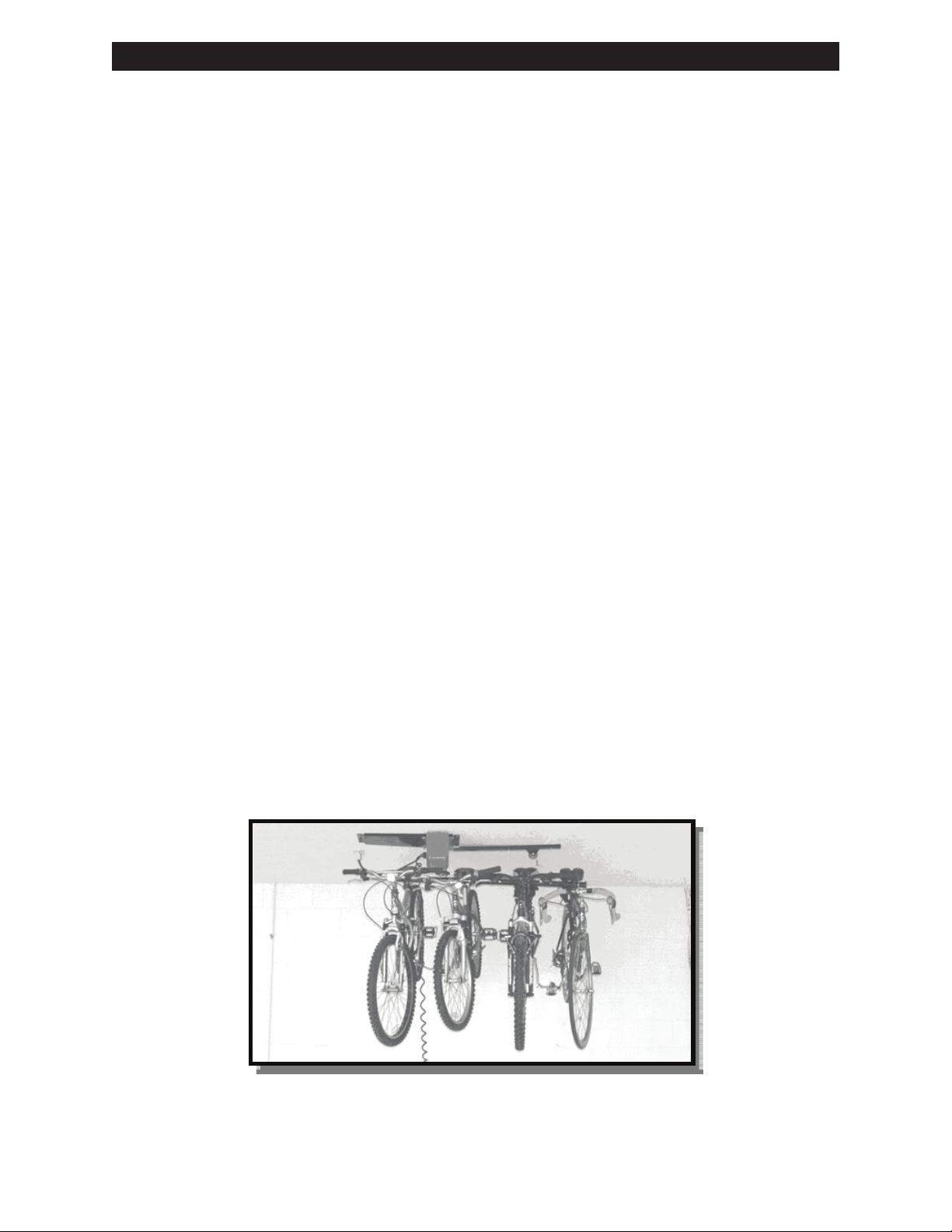
Hooks x4 (H) Bike Cables x2 (I) Bonus Storage Net (J)
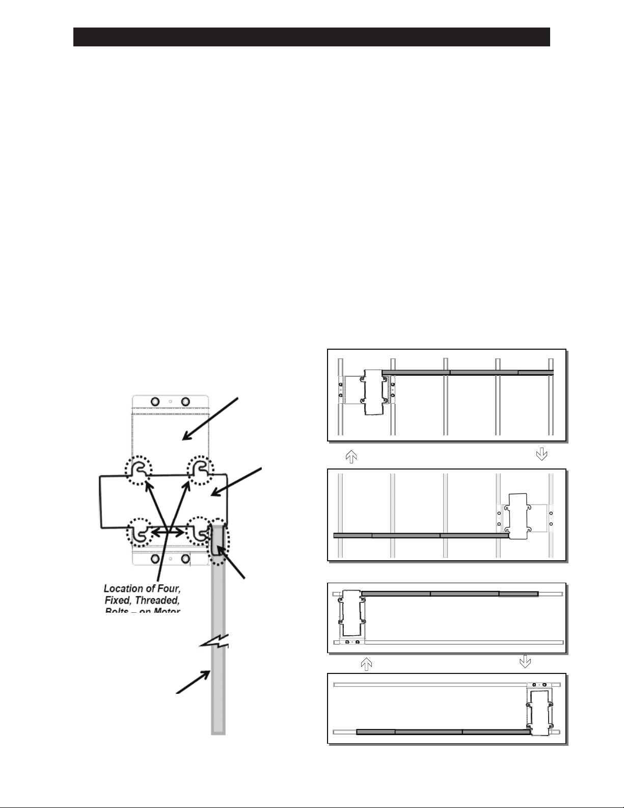
IMPORTANT NOTE
The motor mounting plate (A)
and motor hoist (B) are bolted
together when shipped. IT IS
NECESSARY to remove the
motor hoist from the motor
mounting plate by loosening (it
is not necessary to remove) the
nuts from the fixed, threaded
bolts on the motor mounting
plate. Once loosened, the
motor hoist can easily be slid off
the motor mounting plate.
(B) Motor Hoist
(C) Spacer Channel Bar (D) Spacer Channel Pulley Bar
(F) Hook Bar Connector x2
(H) Hooks x4 (I) Bike Cables x2
IMPORTANT NOTE
The motor mounting plate (A)
and motor hoist (B) are bolted
together when shipped. IT IS
NECESSARY to remove the
motor hoist from the motor
mounting plate by loosening (it
is not necessary to remove) the
bolts on the motor mounting
plate. Once loosened, the motor
hoist can easily be slid off the
motor mounting plate.
5
parts of your GG125 are missing or appear damaged call V-Bro customer service at
1-800-954-6745, Monday – Friday, 8:00 AM to 5:00 PM Eastern Time. Before calling
carefully check the carton as parts may be in the packing material.
MAJOR COMPONENTS
Motor Mounting Plate (A)
Motor Hoist (B)
Spacer Channel Bar (C) Spacer Channel Pulley Bar (D)
Hook Bar Connector x2 (F) Hook Bar End x2 (G)
Hooks x4 (H) Bike Cables x2 (I) Bonus Storage Net (J)
IMPORTANT NOTE
The motor mounting plate (A)
and motor hoist (B) are bolted
together when shipped. IT IS
NECESSARY to remove the
motor hoist from the motor
mounting plate by loosening (it
is not necessary to remove) the
nuts from the fixed, threaded
bolts on the motor mounting
plate. Once loosened, the
motor hoist can easily be slid off
the motor mounting plate.
5
parts of your GG125 are missing or appear damaged call V-Bro customer service at
1-800-954-6745, Monday – Friday, 8:00 AM to 5:00 PM Eastern Time. Before calling
carefully check the carton as parts may be in the packing material.
MAJOR COMPONENTS
Motor Mounting Plate (A)
Motor Hoist (B)
Spacer Channel Bar (C) Spacer Channel Pulley Bar (D)
Hook Bar Connector x2 (F)
Hook Bar End x2 (G)
Hooks x4 (H) Bike Cables x2 (I) Bonus Storage Net (J)
IMPORTANT NOTE
The motor mounting plate (A)
and motor hoist (B) are bolted
together when shipped. IT IS
NECESSARY to remove the
motor hoist from the motor
mounting plate by loosening (it
is not necessary to remove) the
nuts from the fixed, threaded
bolts on the motor mounting
plate. Once loosened, the
motor hoist can easily be slid off
the motor mounting plate.
5
parts of your GG125 are missing or appear damaged call V-Bro customer service at
1-800-954-6745, Monday – Friday, 8:00 AM to 5:00 PM Eastern Time. Before calling
carefully check the carton as parts may be in the packing material.
MAJOR COMPONENTS
Motor Mounting Plate (A)
Motor Hoist (B)
Spacer Channel Bar (C) Spacer Channel Pulley Bar (D)
Hook Bar Connector x2 (F) Hook Bar End x2 (G)
Hooks x4 (H) Bike Cables x2 (I) Bonus Storage Net (J)
IMPORTANT NOTE
The motor mounting plate (A)
and motor hoist (B) are bolted
together when shipped. IT IS
NECESSARY to remove the
motor hoist from the motor
mounting plate by loosening (it
is not necessary to remove) the
nuts from the fixed, threaded
bolts on the motor mounting
plate. Once loosened, the
motor hoist can easily be slid off
the motor mounting plate.
5
parts of your GG125 are missing or appear damaged call V-Bro customer service at
1-800-954-6745, Monday – Friday, 8:00 AM to 5:00 PM Eastern Time. Before calling
carefully check the carton as parts may be in the packing material.
MAJOR COMPONENTS
Motor Mounting Plate (A)
Motor Hoist (B)
Spacer Channel Bar (C) Spacer Channel Pulley Bar (D)
Hook Bar Connector x2 (F) Hook Bar End x2 (G)
Hooks x4 (H) Bike Cables x2 (I) Bonus Storage Net (J)
IMPORTANT NOTE
The motor mounting plate (A)
and motor hoist (B) are bolted
together when shipped. IT IS
NECESSARY to remove the
motor hoist from the motor
mounting plate by loosening (it
is not necessary to remove) the
nuts from the fixed, threaded
bolts on the motor mounting
plate. Once loosened, the
motor hoist can easily be slid off
the motor mounting plate.
(G) Hook Bar End x2
(J) Bonus Storage Net
Mounting plate is attached together
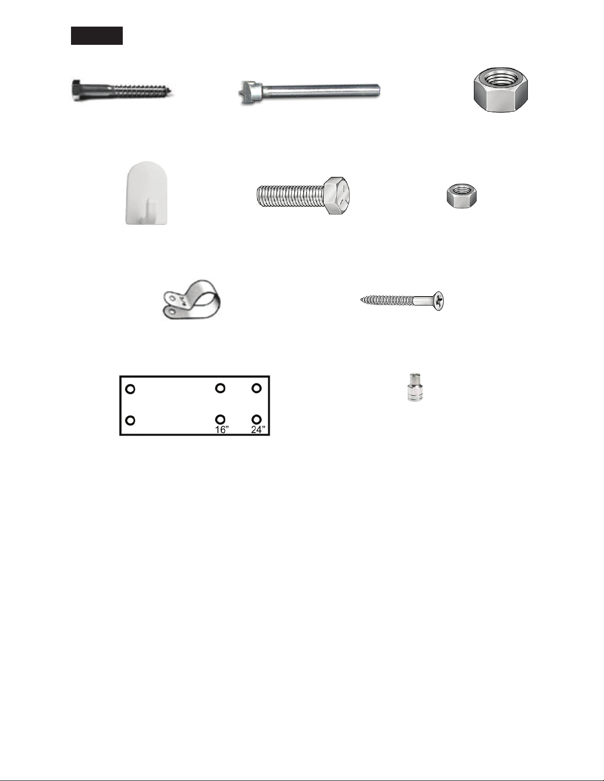
by using 3 of (P) bolts.