V-Bro Products Garage Gator GGR220 Installation instructions

SAVE THIS MANUAL FOR FUTURE REFERENCE
Distributed Exclusively by: V- BRO PRODUCTS, LLC
www.garagegator.com
For technical questions and replacement parts,
Please call 1-888-GATOR-08 -- Local: 352-343-5438
YouTube installation videos can be found at: www.garagegator.com
BY V-BRO PRODUCTS
RESIDENTIAL
MOTORIZED
STORAGE UNIT
Model:GGR220
INSTALLATION, OPERATING,
AND SAFETY INSTRUCTIONS
www.garagegator.com
888-GATOR-08

SAVE THIS MANUAL FOR FUTURE REFERENCE
TABLE OF CONTENTS Garage Gator Motorized Storage Unit
2
Safety Information.....................................................................................3
Tools Needed............................................................................................4
Carton Inventory .......................................................................................5
Major components......................................................... 5
Parts ............................................................................... 6
Installation Instructions .............................................................................7
1 – Determine motor mounting plate location on the ceiling ......7
2 – Install the motor mounting plate to the ceiling.......................8
3 – Attach the motor hoist to the motor mounting plate .............9
4 – Connect and install the rst spacer channel bar ...................10
5 – Connect and install the second spacer channel bar .............11
6 – Connect and install the spacer channel pulley bar ...............12
7 – Install the cable over the channel bar pulley.........................13
8 – Assemble the hook bar .........................................................14
9 – Attach the hook bar to the cables.........................................14
10 – Install the hand control switch holder hook ........................15
11 – Plug in the unit ....................................................................15
12 – Test the unit.........................................................................15
13 – Using the key lock feature...................................................15
Operating Instructions ............................................................................16
Contact Information................................................................................17
Maintenance ...........................................................................................17
Specications..........................................................................................17
Limited Warranty.....................................................................................18

SAVE THIS MANUAL FOR FUTURE REFERENCE
SAFETY INFORMATION Garage Gator Motorized Storage Unit
3
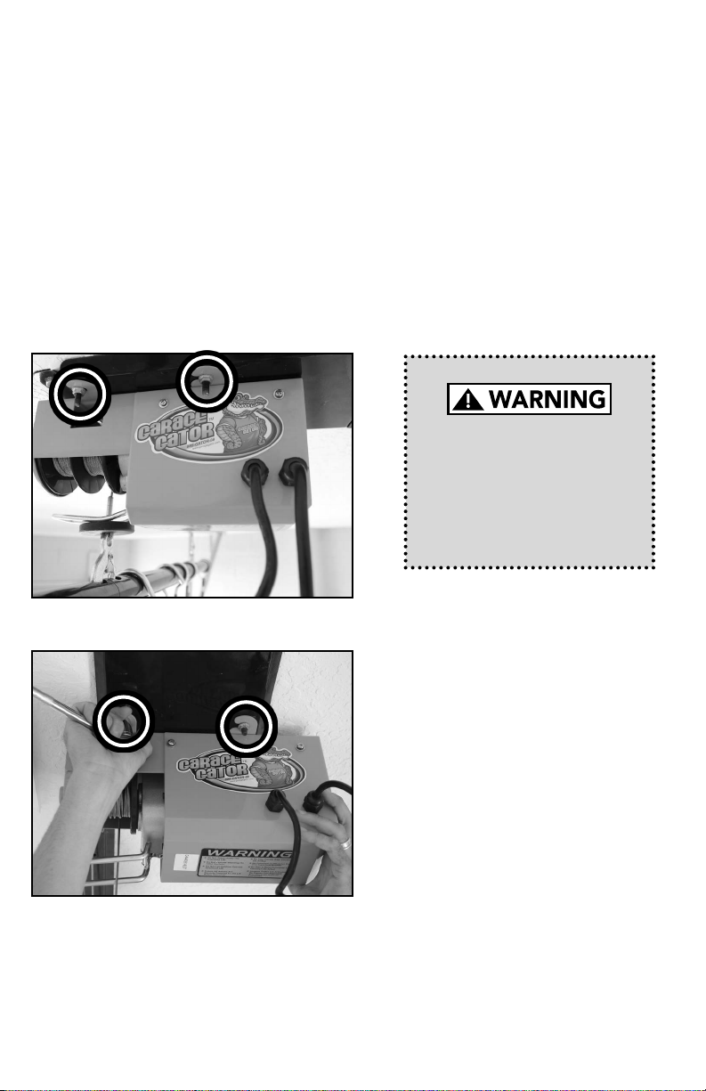
When you see the WARNING safety symbol on the following pages this will
alert you of the possibility of serious injuries or death if you do not comply
with the corresponding instructions. The hazard may come from something
mechanical or from electric shock. Read the instructions carefully!
To reduce the risk of
severe injury or death:
1. READ AND FOLLOW ALL SAFETY, INSTALLATION AND OPERATION
INSTRUCTIONS. If you have any questions or do not understand an
instruction contact V-Bro Products.
2. Do not use to lift people or animals.
3. Do not use to support a load over people or animals.
4. Never operate while hand(s) are near moving parts.
5. Do not stand under lift.
6. Let unit cool down for 5 minutes after every cycle.
7. Install on a at level ceiling, or open rafters. Will not operate correctly if
installed on an angle.
8. Visually inspect trusses for damage before installing your GGR220.
WARNING: THIS IS A DO IT YOURSELF (DIY) PROJECT. DO NOT ATTEMPT THIS INSTALLATION
WITHOUT A BASIC UNDERSTANDING OF THE CONTENTS IN THESE ASSEMBLY
INSTRUCTIONS. IF YOU ARE NOT CONFIDENT WITH LOCATING AND ANCHORING THE
GARAGE GATOR TO THE CEILING JOISTS, DO NOT ATTEMPT THIS INSTALLATION WITHOUT
SOMEONE WHO IS.
WARNING: DO NOT EXCEED THE WEIGHT LIMITS (Based on model used)
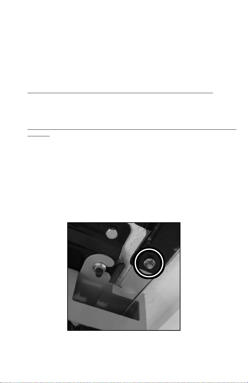
WARNING: This weight limit is based on all lag bolts being secured in the CENTER of the joists a
wood framed garage. The joists must have a minimum 2” x 6” (standard lumber) cross section, 24”
(or less) apart, with at least 2” of penetration from each lag screw used. For truss framed garage
ceiling structures, joists with a 2” x 4” (bottom truss cord) cross section is acceptable.
Do not climb on or (if you have a platform) do NOT hang from.
BOTTOM LINE...BE CAREFUL, THESE INSTRUCTIONS, WARNINGS AND NOTES DO NOT
REPLACE YOUR SOUND JUDGMENT AND DECISION MAKING. IF, FOR ANY REASON, YOU
FEEL THE QUALITY OF YOUR CEILING STRUCTURE IS IN QUESTION, DISCONTINUE THE
INSTALLATION PROCESS IMMEDIATELY. USE THE GARAGE GATOR WISELY AND ENJOY
RECLAIMING YOUR GARAGE!

SAVE THIS MANUAL FOR FUTURE REFERENCE
TOOLS NEEDED Garage Gator Motorized Storage Unit
4
Power drill with 1 16” wood drill bit
Step ladder
Pliers
Safety glasses
Ratchet and ½” socket
Adjustable, open ended wrench
Phillips screwdriver
Tape measure
Pencil
Stud nder (optional)
Gloves when handling the cable

SAVE THIS MANUAL FOR FUTURE REFERENCE
CARTON INVENTORY Garage Gator Motorized Storage Unit
5
Carefully inspect your new motorized storage unit for any possible damage and/or shortage
of parts. Separate all major components and parts as detailed below on the next page.
Do not attempt installation if parts are damaged or missing. If parts of your GGR220 are
missing or appear damaged, call V-Bro customer service at 1-888-GATOR- 08,or Locally at
352-343-5438, Monday - Friday, 9:00 AM to 5:00 PM Eastern Time. Before calling carefully
check the carton as parts may be in the packing material.
MAJOR COMPONENTS
Motor Mounting Plate (A)
Spacer Channel Bar x2 (C)
Hook Bar Center x1 (E)
Hooks x8 (H)
Motor Hoist (B)
Spacer Channel Pulley Bar (D)
Hook Bar Connector x2 (F)
Bike Cables x4 (I)
Hook Bar End x2 (G)
Bonus Storage Net (J)
IMPORTANT NOTE
The motor mounting plate (A)
and motor hoist (B) are bolted
together when shipped. IT IS
NECESSARY to remove the
motor hoist from the motor
mounting plate by loosening (it
is not necessary to remove) the
nuts from the xed, threaded
bolts on the motor mounting
plate. Once loosened, the
motor hoist can easily be slid
off the motor mounting plate.

SAVE THIS MANUAL FOR FUTURE REFERENCE
6
PARTS
K
N
R
T
S
O P Q
L M
Drawings & photos for illustrative purposes only – actual parts may vary from those
pictured. Parts are not shown actual size.
3” Lag bolt x12 5/16” nut x4
(shipped attached to part A)
hand control switch holder hook x1
power cord cable clamps
x2
2” wood screws x2 ¼” X ½” bolt x2 6mm nut x3
¾” hole saw drill bit x1 paper motor mounting template x1
13mm socket x1

SAVE THIS MANUAL FOR FUTURE REFERENCE
INSTALLATION INSTRUCTIONS Garage Gator Motorized Storage Unit
7
Step 1
Determine motor mounting plate location on the ceiling
• Choose a location in your garage where you would like to install your Garage Gator
model GGR220. An unobstructed operating space of at least 3 feet by 9 feet is
required. The motor mounting plate (A) should be installed at least 3 feet away from
walls or any other obstructions.
• The GGR220 is designed to be installed either perpendicular or parallel to the
ceiling joists and can be installed using 16” or 24” spacing.
• Select an installation location close to a power supply (preferably a ceiling outlet).
• In the chosen installation area, determine the direction of the ceiling joists and the
exact location of the ceiling joists by using a stud nder or a very ne drill bit.
• Four installation options are illustrated below. Note how the motor mounting plate
(A) and motor hoist (B) are positioned for your installation. In particular, the location
of the 4 xed, threaded bolts on the motor mounting plate and the 4 1/2” spacer
channel bar attachment tab on the motor hoist.
• Layout on oor before installing to be sure all components are present. This will
also make it easier to visualize how the unit will install. Be sure to remember that the
actual installation will be overhead, therefore the oor layout will be upside down.
Perpendicular To Joint Installations
OPTION
B
Perpendicular To Joint Installations
OPTION
C
OPTION
D

SAVE THIS MANUAL FOR FUTURE REFERENCE
8
Step 2
Install the motor mounting plate to the ceiling
• Position the paper motor mounting template (S) in the installation area and mark
with a pencil the four locations where the lag bolts will be fastened.
• It is very important that the lag bolts are fastened to the center of the joists.
Use the hole saw drill bit (R) or cut away the drywall with a utility knife to obtain
an unobstructed view of the width of the joists so the exact center can easily be
determined (covered ceilings only). It may be necessary to again use the motor
mounting template and a pencil to mark where the lag bolts are to be fastened.
• Using a power drill with a 1/8” drill bit attached drill four pilot holes into the center
of the joists.
• Identify your installation option by referring to the illustrations on page 7. Determine
how the motor mounting plate should be rotated – where the xed, threaded bolts
should be located – prior to fastening to the joists. Ensure your motor mounting
plate is rotated properly before placing the motor mounting plate on the ceiling.
(SEE ILLUSTRATIONS ON PAGE 7)
• Place the motor mounting plate (A) without the motor hoist (B) attached over the
screw holes. (To remove the motor hoist from the motor mounting plate loosen (it is
not necessary to remove) the nuts from the xed bolts on the motor mounting plate
and slide off the motor hoist.)
Use the ratchet or drill and 1/2” socket fasten four of the 3” lag bolts (K) into the joists
until the motor mounting plate is securely fastened. (SEE FIG. 1)
Motor mounting plate must
be fastened to wooden joists
in the building framing. Do
not fasten to drywall, particle
board, plaster or other such
materials.
FIG. 1

SAVE THIS MANUAL FOR FUTURE REFERENCE
9
Step 3
Attach the motor hoist to the motor mounting plate.
• Identify your installation option by referring to the illustrations on page 7. Determine
how the motor hoist should be rotated – which direction the 4 1/2” spacer channel
bar attachment tab should be pointing. Ensure your motor hoist is rotated
properly before placing the motor hoist on the motor mounting plate. (SEE
ILLUSTRATIONS ON PAGE 7)
• Slide the mounting tabs on the motor hoist (B) over top of the four xed, threaded
bolts on the motor mountain plate (A). (If there is not enough room between the
nuts and the motor mounting plate for the motor hoist mounting tabs it will be
necessary to loosen the nuts by turning them counter clockwise.)
• Once the motor hoist is properly positioned on the motor mounting plate you can
tighten the nuts with a ratchet or adjustable wrench until the motor hoist is securely
attached to the motor mounting plate. (SEE FIG. 3)
Slide motor hoist until the
tabs are rmly against the
threaded bolts. Do not leave
any space between the bolts
and the enclosed end of the
mounting tabs.
FIG. 3
FIG. 3A

SAVE THIS MANUAL FOR FUTURE REFERENCE
10
Step 4
Connect and install the rst spacer channel bar
• Press the spacer channel bar ush with the ceiling and mark with a pencil where a
lag bolt will be used to attach the bar to the joist.
– Perpendicular joist installation (option A or B on page 7). Make a mark at either
the 16” hole or 24” hole depending on your joist spacing. Remove the spacer
channel bar.
– Parallel joist installation (option C or D on page 7). Make a mark at the 21” hole.
Remove the spacer channel bar.
• It is very important that the lag bolt is fastened to the center of the joist. Use
the hole saw drill bit (R) or cut away the drywall with a utility knife to obtain an
unobstructed view of the width of the joist so the exact center can easily be
determined. It may be necessary to reposition the spacer channel pulley bar and
mark with a pencil where the lag bolt is to be fastened.
• Using a power drill with a 1/8” drill bit attached drill a pilot hole into the center of
the joist.
• Insert the ared end (the end without a x nut) of a spacer channel bar onto the
xed bolt coming down from the motor plate tab above the cable spools on the
motor hoist. (SEE FIG. 4)
• Attach a 6mm nut (Q) to the xed bolt and tighten with a ratchet or adjustable
wrench until the spacer channel bar is securely fastened to the motor hoist. (SEE
FIG. 4)
• Place a lag bolt(s) (K) and using the ratchet fasten the bolt(s) into the joist(s) until
the spacer channel bar is securely fastened.
FIG. 4

SAVE THIS MANUAL FOR FUTURE REFERENCE
11
Step 5
Connect and install the second spacer channel bar
• Line up the hole in the ared end (the end without a xed nut) of the spacer channel
bar (C) over the hole in the installed spacer channel pulley bar. Thread a 1/4” x 1/2”
bolt (P) into the hole and nger tighten. (SEE FIG. 5)
• Press the spacer channel bar ush with the ceiling and mark with a pencil where the
lag bolt(s) will be used to attach the bar to the joist(s).
– Perpendicular joist installation (option A or B on page 7). There are holes in
the spacer channel bar at 16”, 24” and 32” from the lag bolt in the rst installed
spacer channel bar. Measure from the lag bolt and determine the appropriate
hole(s) depending on your joist spacing. (Installations with 16” spacing will insert
two lag bolts in this spacer channel bar – at 16” and 32” from the rst lag bolt.
Installations with 24” spacing will have one lag bolt). Remove the spacer channel
bar.
– Parallel joist installation (option C or D on page 7). Make marks at the 5” and
21” holes on the spacer channel bar – measuring from the ared end of this
spacer channel bar. Remove the spacer channel bar.
• It is very important that the lag bolts is fastened to the center of the joist(s). Use
the hole saw drill bit (R) or cut away the drywall with a utility knife to obtain an
unobstructed view of the width of the joist(s) so the exact center can easily be
determined. It may be necessary to reposition the spacer channel pulley bar and
mark with a pencil where the lag bolt(s) are to be fastened.
• Using a power drill with a 1/16” drill bit attached drill pilot hole(s).
• Line up the hole in the ared end (the end without a xed nut) of the spacer
channel bar (c) over the hole in the installed spacer channel pulley bar. Thread a
1/4” x 1/2” bolt into the hole and tighten with a ratchet or adjustable wrench until
the spacer channel bar is securely fastened. (SEE FIG. 5)
• Place a lag bolt(s) (K) and using the ratchet fasten the bolt(s) into the joist(s) until
the spacer channel bar is securely fastened.
FIG. 5

SAVE THIS MANUAL FOR FUTURE REFERENCE
12
Step 6
Connect and install the spacer channel pulley bar
• Press the spacer channel bar ush with the ceiling and mark with a pencil where the
lag bolts will be used to attach the bar to the joist.
– Perpendicular joist installation (option A or B on page 7). There are sets of
holes on each side of the spacer channel bar at 16” and 24” from the last lag bolt
installed. Measure from the last lag bolt and determine the appropriate holes
depending on your joist spacing. Remove the spacer channel pulley bar.
– Parallel joist installation (option C or D on page 7). Make marks at one hole
before the pulley and one hole after the pulley. Remove the spacer channel pulley
bar.
• It is very important that the lag bolts are fastened to the center of the joist. Use
the hole saw drill bit (U) or cut away the drywall with a utility knife to obtain an
unobstructed view of the width of the joist so the exact center can easily be
determined. It may be necessary to reposition the spacer channel pulley bar and
mark with a pencil where the lag bolts are to be fastened.
• Using a power drill with a 1/8” drill bit attached drill two pilot holes into the center
of the joists.
• Line up the hole in the end opposite the pulley of the spacer channel pulley bar
(D) over the hole in the second spacer channel pulley bar. Thread a 1/4” x 1/2”
bolt into the hole and tighten with a ratchet or adjustable wrench until the spacer
channel pulley bar is securely fastened. (SEE FIG. 6)
• Place a washer (L) over the lag bolts (K) and using the hex key (W) fasten the screws
into the joist until the spacer channel pulley bar is securely fastened to the joist.
FIG. 6

SAVE THIS MANUAL FOR FUTURE REFERENCE
13
Step 7
Install the cable over the channel bar pulley
• Plug in the motor hoist (B) to the nearest 110
volt power outlet.
• Use the hand control switch and safely lower
the cables until 9 feet of cable is visible.
• Unplug the power cord from the outlet.
• Temporarily remove the pulley at the end of
the spacer channel pulley bar (D). (use pliers
to remove the cotter pin then remove the
clevis pin to release the pulley)
(SEE FIG. 7A & 7D)
• Place the cable coming out of the rectangular
opening closest to the spacer channel bar
(indicated by arrow in gure 7B) over the top
of the pulley at the end of the spacer channel pulley bar. (SEE FIG. 7B & 7C)
CAUTION: Use care when handling the cables – frayed or rough spots on the
cable could cause injury.
• Once the cable has been placed over the pulley reinstall the pulley to its original
position, insert the clevis pin and refasten the cotter pin. (SEE FIG. 7D)
FIG. 7D
FIG. 7A FIG. 7B FIG. 7C
To reduce the risk of electrical
shock, this equipment has
a grounded type plug that
includes a third (grounding)
pin. This plug will only t a
grounded type outlet. If you
do not have a grounded outlet,
contact a qualied electrician
to install one. DO NOT alter
the plug in any way.
FIG. 7E
Cotter Pin
Pulley
Cable
Clevis Pin

SAVE THIS MANUAL FOR FUTURE REFERENCE
14
Step 8
Step 9
Assemble the hook bar
• Assemble the three middle pieces of the hook bar by lining up the spring clips from
the hook bar center (E) to the holes of the hook bar connectors (F). (SEE FIG. 8A)
• Slide hooks (H) and bike cables (I) onto the assembled piece. (SEE FIG. 8B & 8C)
• Attach each hook bar end (G) to the assembled middle section by lining up the
slotted holes from the hook bar end to the holes of the hook bar connectors.
(SEE FIG. 8D)
Attach the hook bar to the cables
• Attach the hooks at the end of the cables to the hook
bar by pressing in the spring clip and inserting the hook
into the opening on the hook bar. (SEE FIG. 9) Insert
each hook so the spring clip on the hook is pointing
toward the hook bar center (E).
NOTE: You may wish to slide a hook or bike cable to the
hook bar end sections – the area on the far side of the
hook – before attaching the hook to the bar.
Be sure the spring clips
are fully inserted into the
connector bars.
FIG. 9
FIG. 8A
FIG. 8B FIG. 8C FIG. 8EFIG. 8D

SAVE THIS MANUAL FOR FUTURE REFERENCE
15
Step 10
Step 11
Step 12
Step 13
Install the hand control switch holder hook
• Secure the hand control switch holder hook
(M) to a convenient location on the closest
appropriate wall by removing the protective
paper from the adhesive strip then adhere
the hook to the wall by applying pressure
with your ngers. (SEE FIG. 10)
Plug in the unit
• Plug in the motor hoist (B) to the nearest 110 volt power outlet. You may wish to
use the power cord cable clamps (N) and the 2” wood screws (S) to secure the
power cord or extension cord (not provided) to the ceiling or wall.
Test the unit
• Press and hold the rocker switch on the hand control
to raise and lower the hook bar. When the hook bar
reaches the uppermost travel point the ring above
the cable hook will trigger the limit switch ceasing
upward movement. (SEE FIG. 11)
Using the lock key feature
• To prevent unauthorized use the GGR220 is
equipped with a key lock feature. (SEE FIG. 12)
• When the key is turned of the “OFF” position and
removed from the hand control switch the unit will
not function until the key is reinserted and turned to
the “ON” position.
FIG. 10 FIG. 10A
FIG. 11
FIG. 11A
FIG. 12
FIG. 12A

SAVE THIS MANUAL FOR FUTURE REFERENCE
Bikes – (2) options
Option One:
• ** Use the hooks to hold bikes securely in place, by
placing the red end of the hook around the neck of
the bike seat. See fig 13.
Option Two:
• Loop one piece of the bike cable through the rim of
the front tire then connect the clip to the oblong ring attached to the hook bar.
• Loop the second piece of the bike cable through the rim of the back tire then
connect the clip to the oblong ring attached to the hook bar.
Golf Bags
• Golf bags should be hung by the carrying handle – NOT the shoulder strap.
Canoe/Kayak – (capacity on hook bar must not exceed 200 pounds)
Spare Tires
Storage Net – ideal for balls, toys, helmets, etc.
Ladders
Tools
OPERATING INSTRUCTIONS Garage Gator Motorized Storage Unit
16
TO RAISE OR LOWER THE HOOK BAR:
TO LOAD THE HOOK BAR:
Examples of items that can be stored:
• **Do not stand under the lift.
• Turn the key in the hand control switch to the “ON” position.
• Press and hold the rocker switch in the direction you want the hook
bar to travel.
• Release the switch when desired location is reached.
• Lower the hook bar to a comfortable height.
• **Evenly distribute the weight of articles stored.
• Do not overload the hook bar – maximum capacity is 220 pounds.
• Be sure items are secured before raising the hook bar.
• **Make sure load is secure before lifting.
DO NOT OVERLOAD THE HOOK BAR.
Maximum capacity is 220 pounds for all articles on the hook bar. Be sure to distribute weight evenly.
THE GGR3672PS
(PLATFORM SERIES) IS AVAILABLE.
FIG. 13
FIG. 13

SAVE THIS MANUAL FOR FUTURE REFERENCE
CONTACT INFORMATION Garage Gator Motorized Storage Unit
17
V-Bro Products is on call. Installation and service information as well as ordering repair parts
is as near as your telephone Monday - Friday 9:00 AM to 5:00 PM Eastern Time (subject to
holidays). Contact us toll free.
V-Bro Products
28114 County Road 561
Tavares, Florida 32778
888-GATOR-08
Locally: 352-343-0702
fax: 352-742-0702
email: info@garagegator.com
1-888-GATOR-08
Locally: 352-343-5438
MAINTENANCE / SAFETY CHECK Garage Gator Motorized Storage Unit
1. Check to be sure the motor is properly attached to its mounting plate. Make sure
that the nuts bolts are tight. Frequently check the hardware as vibration may cause
loosening of nuts and bolts.
2. Periodically check the condition of the electrical cords, plugs and controls.
3. Be sure to distribute weight evenly.
4. Check crimps and cables to be sure that everything is intact – be sure to wear gloves
when doing this.
SPECIFICATIONS Garage Gator Motorized Storage Unit
Model .........................................................................................Garage Gator 220
Load Capacity.............................................................................................. 220 lbs
Lifting Height..........................................................................................117 inches
Lifting Speed .............................................................................................33 ft/min
Cable Length..........................................................................................165 inches
Cable Diameter ...................................................................................... 0.118 inch
Voltage ................................................................................120V / 60HZ 4.5 Amps
Motor............................................................................................................ 3/5 HP
www.garagegator.com
888-GATOR-08

SAVE THIS MANUAL FOR FUTURE REFERENCE
LIMITED WARRANTY
What is covered: Any defect in material and workmanship from personal, normal household
use in accordance with the Owner’s Manual.
For how long: Garage Gator Model 220. One year from date of purchase.
Who gets the warranty: The warranty is limited to the consumer who originally purchased
the product.
Geographic scope: This warranty applies only to the Residential Motorized Storage Unit
purchased in the United States and Canada.
What we will do: If your Residential Motorized Storage Unit is defective, we will send
replacement parts or, at our option, replace it at no charge to you. If we send replacement
parts for your Residential Motorized Storage Unit, we may use new or reconditioned parts.
If we choose to replace your Residential Motorized Storage Unit, we may replace it with a
new or reconditioned one of the same or similar design.
Limitations: IMPLIED WARRANTIES, INCLUDING THOSE OF FITNESS FOR A PARTICULAR
PURPOSE AND MERCHANTABILITY (AN UNWRITTEN WARRANTY THAT THE PRODUCT
IS FIT FOR ORDINARY USE) ARE LIMITED TO ONE YEAR FROM DATE OF PURCHASE. WE
WILL NOT PAY FOR: LOSS OF USE OF YOUR RESIDENTIAL MOTORIZED STORAGE UNIT
OR ITS FAILURE TO WORK ANY SPECIAL, INCIDENTAL OR CONSEQUENTIAL DAMAGES;
ANY DAMAGES RESULTING FROM MISUSE OR MODIFICATION OF YOUR RESIDENTIAL
MOTORIZED STORAGE UNIT. Some states and provinces do not allow limitations on how
long an implied warranty lasts or the exclusion of incidental or consequential damages, so
the above exclusions may not apply.
How to get warranty service: To get warranty service for your Residential Motorized
Storage Unit, you must provide proof of date and place of purchase of the product. Trained
representatives will assist in diagnosing the problem and will arrange to supply you with
required parts for repair.
What this warranty does not cover: This warranty does not cover installation, commercial
use, defects resulting from accidents, damage while in transit to our service location
or damage resulting from alterations, misuses or abuse, lack of proper maintenance,
unauthorized repair or modications of the product, afxing of any attachment not provided
with the product, staples through wiring, pinched or broken wires, broken cables, power
outages, use of extension cords, missing or damaged parts or discounted, clearance, nal
sale or taped cartons, re, ood, acts of God, or failure to follow the Owner’s Manual. This
warranty is the only one we will give on your Residential Motorized Storage Unit, and it
sets forth all responsibilities regarding your Residential Motorized Storage Unit. There
are no other express warranties.
State and Province rights: This warranty gives you specic legal rights, and you may also
have other rights that vary from state to state and province to province.
18
Other manuals for Garage Gator GGR220
1
Table of contents
Other V-Bro Products Storage manuals
Popular Storage manuals by other brands

Smacq Technologies
Smacq Technologies PCI-1132 user manual

Tennsco
Tennsco 1870 Assembly Instructions/Parts Manual

Newer Technology
Newer Technology Guardian Maximus owner's manual

Western Digital
Western Digital WD Elements WDE1UBK10000 quick guide

The Handy
The Handy 01694 quick start guide

Seagate
Seagate ST336737LW product manual