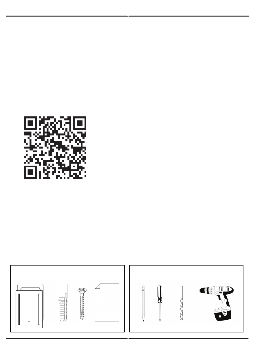
V-TAC VT-8505 User manual

WARNING!
1. Please make sure to turn off the power before starting the installation.
2. Proper grounding should be ensured throughout the installation.
4. Installation should only be done by a certified electrician.
3. The light source of this luminaire is not replaceable, when the light source
reaches its end of life the whole luminaire should be replaced.
WEEE Number: 80133970
INSTALLATION INSTRUCTION
MIRROR LIGHTS
This marking indicates that this
product should not be disposed
of with other household wastes.
Caution, risk of electric
shock.
TECHNICAL DATA:
IN CASE OF ANY QUERY/ISSUE WITH THE PRODUCT, PLEASE REACH OUT TO US AT: SUPPORT@V-TAC.EU
FOR MORE PRODUCTS RANGE, INQUIRY PLEASE CONTACT OUR DISTRIBUTOR OR NEAREST DEALERS.
V-TAC EUROPE LTD. BULGARIA, PLOVDIV 4000, BUL.L.KARAVELOW 9B
2
YEARS
WARRANTY
*
Anti-fog
MODEL WATTS LUMENS BEAM
ANGLE CRI VOLTAGE/FREQUENCY UNIT SIZE IP
RATING
DEMISTER
PAD
BODY
TYPE
VT-8505 17W 600LM 120° >80 AC:200–240V, 50/60Hz H500xW390xD35mm IP44 330×160mm Iron
VT-8700 30W 750LM 120° >80 AC:200–240V, 50/60Hz H700xW500xD35mm IP44 450×250mm Iron
VT-8701 25W 750LM 120° >80 AC:200–240V, 50/60Hz H700xW500xD35mm IP44 450×250mm Iron
VT-8800 38W 700LM 120° >80 AC:200–240V, 50/60Hz H800xW600xD35mm IP44 560×330mm Iron
VT-8601 25W 750LM 120° >80 AC:200–240V, 50/60Hz øD:600xD35mm
øD:600xD35mm
IP44 Dia360mm Iron
VT-8602 25W 750LM 120° >83 AC:220-240V, 50Hz IP44 Dia360mm Iron

INTRODUCTION & WARRANTY
Thank you for selecting and buying V-TAC product. V-TAC will serve you the
best. Please read these instructions carefully before starting the installation
and keep this manual handy for future reference. If you have any another
query, please contact our dealer or local vendor from whom you have
purchased the product. They are trained and ready to serve you at the best.
The warranty is valid for 2 years from the date of purchase. The warranty
does not apply to damage caused by incorrect installation or abnormal wear
and tear. The company gives no warranty against damage to any surface due
to incorrect removal and installation of the product. The products are suitable
for 10-12 Hours Daily operation. Usage of product for 24 Hours a day would
void the warranty. This product is warranted for manufacturing defects only.
IMPORTANT SAFETY INFORMATION
• Please read these instruction carefully before attempting to install this
product. It is advisable to keep these instructions in a safe place for future
reference.
• We recommend that you consult a qualified electrician. All electrical installa
tion must be carried out in accordance with the current IEE wiring regulations
(BS7671) and the latest relevant building regulations.
• This product must not be modified, if any modifications are made, it may
invalidate the warranty and may render the product unsafe.
- This product is for indoor use only.
COMPONENTS TOOLS REQUIRED
Multi-Language Manual QR CODE
Please scan the QR code to access the manual
in multiple languages.

SAFETY INSTRUCTIONS
1. Installation should only be done by a certified electrician.
2. Before commencing installation or maintenance, isolate the main electrical.
supply for appropriate circuit at the fuse board.
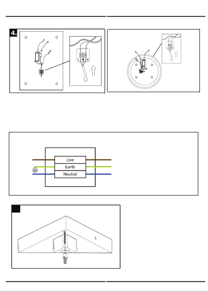
3. This product is only suitable for connecting to a 240V 50Hz supply.
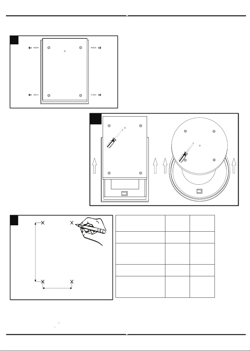
4. The mirror light should be mounted onto a secure surface.
5. When installing, please take care to avoid water pipes, joints, and electrical
cables.
6. This product has a rating of IP44.
7. Do not exceed or stretch cables.
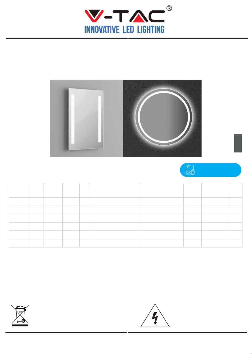
PRODUCT OVERVIEW
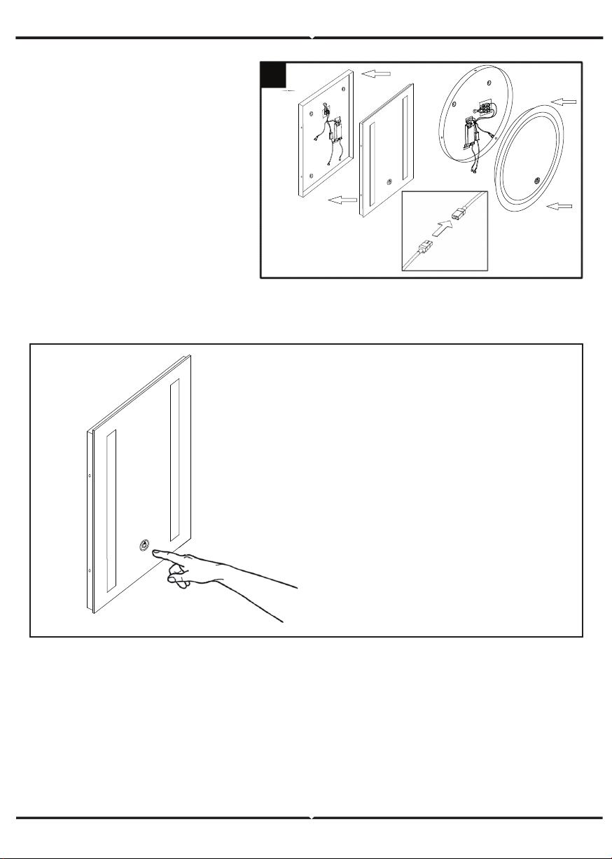
• This illuminated LED mirror is a sleek addition to any bathroom, providing
beautiful lighting.
• The mirror light features stylish soft-edge corners, as well as an illuminated
front face, which is perfect for everyday tasks.
• The mirror light is built-in with demister pad which guarantees that the
mirror light will always stay perfectly clear.
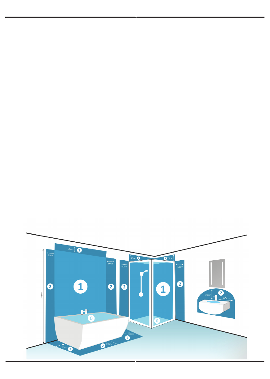
TYPES OF BATHROOM LIGHTING ZONES:
0 - Inside the bath or shower. Must be SELV (12V Max) due to water submer-
sion. Minimum rating of IP67.
1 - 225cm above the bath or shower. Minimum rating of IP44.
2 - The area stretching to 60cm outside the bath or shower, and 60cm from
the water outlet of the sink. An IP Rating of at least IP44 is required.
Outside Zones - Anywhere outside zones 0, 1 and 2, where water jets are not
used for cleaning purposes, the general rules of BS7671 apply.
NOTE: V-TAC Mirror Lights are IP44 rated and suitable for installation
in zone 2 and the outside zones ONLY.

INSTALLATION INSTRUCTIONS
Step 1: Lay the mirror face down and
remove the screws with a Philips head
screw driver.
Note: Be careful to lay the mirror
on a padded surface, that will not
cause any scratches or abrasions.
1.
Step 2: Carefully separate
the back box from the
glass mirror and pierce
the rubber grommet.
Note: The rubber
grommet will isolate
and trap any steam
to ensure the mirror
remains protected.
3.
A(mm) B(mm)
ITEM NO
VT-8505
VT-8700
VT-8701
VT-8800
VT-8601
VT-8602
300 500
400 600
268 268
200 300
B
A
Step 3: Carefully mark your desired position for the mirror using the
dimensions shown above. Then proceed to drill the holes for the Rawl plugs
and screws.
Note: Be careful before drilling to avoid any wiring or water pipes.
3.
2.

Step 4: Thread a 3-core mains cable through the rubber grommet in the back
box and connect it to the junction box.
Note: Please refer to the wiring diagram as shown below.
Step 5: Insert the Rawl
plugs into the pre-drilled
holes and then secure the
back box to the wall using
the four screws provided.
4.
5.
L N
WIRING DIAGRAM
Live Supply can be Red or Brown.
Earth Supply is Green and Yellow.
Neutral Supply can be Blue or Black.
Luminaire Main Supply
L N

TOUCH SWITCH AND CCT CHANGING OPERATIONS:
MAINTENANCE & CAREFULLY
1. Ensure that the power is disconnected prior to cleaning.
Note: The touch switch and CCT changing operation is only designed
for VT-8701 and VT-8602. The other models [VT-8505, VT-8700,
VT-8800, VT-8601] work with a normal switch.
2. To keep the finish of this product, wipe out with soft cloth periodically.
3. Do not use harsh chemical solvents, this may dis-colour or damage the finish.
4. Do not over-tighten screw on the terminal block
Touch Sensor
1. On/Off - Touch to turn the light ON/OFF
2. Colour Temperature - Press and
hold the bottom to change the colour
temperature between cool white and
warm white.
Step 6: Connect the male and
felmale connectors for the
demister pad and LED,proceed
to slot the glass panel over the
back box.Finally,re-insert the
screw to fasten the two parts
together.
(Applicable only for Model No.VT-8701 & VT-8602)
6.
This manual suits for next models
5
Table of contents