Installation instructions
Induction hob
CookTop Teppan Yaki I40
1097806-04
27/07/2023
2
Designation Art. no.
Anthracite silicone FA880 (310ml) B11556
White silicone FA880 (310ml) 1031313
Stone grey silicone FA880 (310ml) 1031314
Marble smoothing agent AA320 (1000ml) B11557
Fugenboy (silicone finishing tool) B75158
Electrical connection
Electrical connections must be carried out by qualified personnel in accordance with the guidelines and standards
for low-voltage installations and the specifications of the local electricity supply companies.
Refer to the identification plate for information on the required mains voltage and current type.
A plug-in appliance may only be connected to a socket outlet with earthing contact, installed according to specifications. An
all-pole mains isolating device with 3 mm contact opening should be provided in the house wiring system. Switches, plug and
socket devices, circuit breakers and fusible cut-outs which are accessible after installation and which have all-poles switching
are permissible as isolating devices. Effective earthing and separately installed neutral and earth conductors ensure safe and
fault-free operation. After installation, live parts and cables with basic insulation must not be accessible. Check old installa-
tions.
▸If the hobs are used at an altitude of over 2,000metres,a reduced performance must be expected.
The appliance is equipped with a connection cable which must be connected to an on-site junction box.
Installation pipe Distribution boxClamp
black
black
yellow/green
N
L1
PE/
220–240 V~
1 1 1 1 1 1 1 1
2 2 2 2 2 2 2 2
Error message U400
Faulty connection:
A pole conductor has been connected to the connection terminal for neutral conductors.
Quickly disconnect the appliance from the mains!
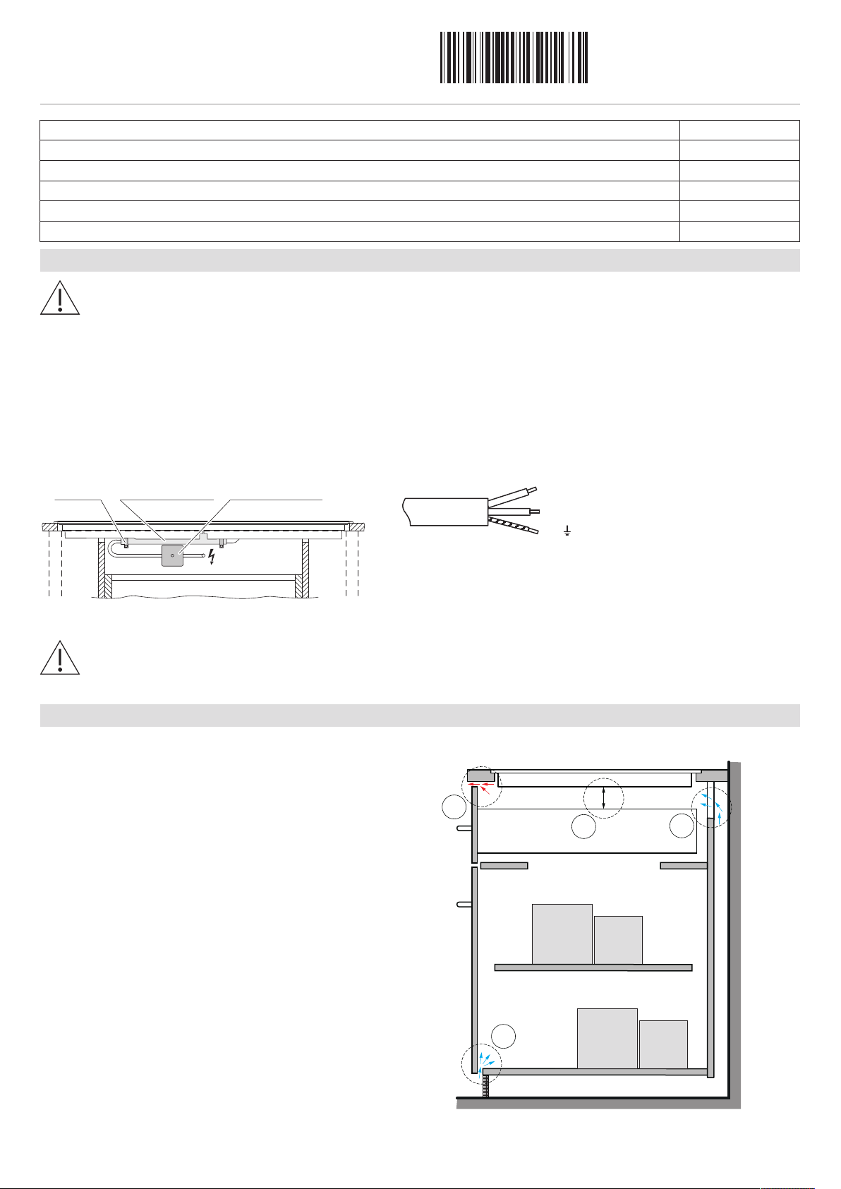
Ventilation
For installation of a V-ZUG induction hob, the following minimum requirements apply:
1. The hot air exhaust should be provided by a ventilation slit
of ≥2mm at the front.
2. A space of ≥10mm in height is required beneath the appli-
ance.
3. Not only exhaust air but also replacement air in the cabinet
should be taken into account. There are different ways to
do this, including:
a) The rear panel of the base unit must be open around
the work surface cut-out to guarantee continuous air circu-
lation through the ventilation slits. The air must be drawn in
from outside the cabinet and be able to circulate freely
from inside the cabinet to the hob. The lower plinth must
not be hermetically sealed. This can be achieved through a
shadow gap at the plinth panel or through the use of a
ventilation grille.
b) Alternatively, a concealed fresh air supply can ensure
air circulation inside the cabinet. In order that enough cold
air can be drawn in, there must be a continuous circulation
of fresh air that extends outside the cabinet. The lower
drawer panel should therefore not hermetically seal the
cabinet.


