manuals.online logo
Brands
  1. Home
  2. •
  3. Brands
  4. •
  5. V-ZUG
  6. •
  7. Hob
  8. •
  9. V-ZUG GAS421 Series User manual

V-ZUG GAS421 Series User manual

Installation instructions
Built-in variants of gas hob
Multi-Sliders GAS411/421
1037456-05
26/07/2023
1037456-05
1
According to the Gas Safety Ordinance of Hong Kong, any gas installation works, including the installation of appli-
ances and connection tubing, must be undertaken by registered gas installers who are registered for the appropriate
classes and are employed by registered gas contractors.
Check that the local connection conditions (gas type and gas pressure) and the appliance setting match before con-
necting the appliance.
The default values for this appliance are provided on the information plate (or on the identification plate).
This appliance is not connected to a combustion by-product outlet. It must be set up and connected according to the
applicable installation conditions. Particular attention must be paid to the relevant ventilation requirements.
If installing into a combustible material, the guidelines and standards for low-voltage installations and fire protection
must be strictly observed.
All leak tests should be done with a soapy water solution. Never use an open flame to check for leaks!
When installing a built-in gas hob on top of a stove cabinet, please check that there is provision for ventilation at the
cabinet to ensure proper operation of the gas hob.
Use approved gas tubing bearing the EMSD approval marking (such as: EMSD APPROVAL
GTXXXX) for connection to appliances.
Do not store any flammable materials, sprays or pressurized containers inside the stove cabinet.
Validity
These installation instructions apply to the following models:
Type Model number Appliance class
31063 GAS411GSBZ Class 3
DIN EN 30-1-1
31064 GAS421GSBZ
General notes
Identification plate
The identification plate is located on the underside of the
hob.
Identification plate
Depending on
appliance, plate
with additional
information
▸Affix the second identification plate (supplied) in an accessible position behind the front of the fitted cabinet beneath the appliance.
Care and maintenance
▸Follow the care and cleaning advice in the operating instructions.
▸Follow the basic maintenance advice in the operating instructions.
Installation instructions
Built-in variants of gas hob
Multi-Sliders GAS411/421
1037456-05
26/07/2023
1037456-05
2
Installation accessories provided
For all installation variants:
Designation Art. no.
4 adjusting braces H61561
Flush installation:
Designation Art. no.
Cementing-in instructions J004133
Sealing strip set H63283
Spacer set H60330
Accessories
Surface-mounted installation:
Designation Article no.
Stainless steel intermediate support for the surface-mounted combination of several hobs 1014361
Black intermediate support for the surface-mounted combination of several hobs 1019199
Flush installation:
Designation Article no.
Steel angle set, hob size: 40 H63771
Designation Art. no.
Instant adhesive for installation of the steel angle (50ml) B11657
Straight mixing nozzle B11656
TREMCLEAN isopropyl alcohol (1000ml) 1056609
Black silicone FA880 (310ml) B11555
Anthracite silicone FA880 (310ml) B11556
White silicone FA880 (310ml) 1031313
Stone grey silicone FA880 (310ml) 1031314
Marble smoothing agent AA320 (1000ml) B11557
Intermediate support kit for the flush-mounted combination of several hobs (contains two intermediate
supports)
H63789
Gas connection
Designation Art. no.
Sealing ring for gas connection 18 × 13 × 5 mm, for long thread. 1030096
Installation instructions
Built-in variants of gas hob
Multi-Sliders GAS411/421
1037456-05
26/07/2023
1037456-05
3
Surface-mounted installation
The layout of the hob to be fitted may differ from the hob illustrated!
H
Y – Y
B
Drawer/
cabinet Side panel
S* ≥81
T≥90
373±1
GAS411GSBZ GAS421GSBZ
600
≥400
≥50
≥50
490±1
600
Ra
H
384
501
Y
Y
Ri
600
≥400
≥50
≥50
490±1
600
Ra
373±1
H
384
501
Ri
Y
Y
* The required clearance must be observed!
Model number B H Corner radius Ra/Ri
GAS411GSBZ, GAS421GSBZ ≥95mm 84 mm 0–5/2mm
BRequired clearance for service replacement over the entire cut-out area.
HDimension from the top of the work surface to the underside of the gas connection
Ri Corner radii of appliance for base plate Ra Outer corner radii of cut-out
SMinimum distance between the top of the work surfaces and any drawer
TMinimum distance between the cut-out in the back and any drawer
Installation
Do not damage the sealing bead.
The sealing bead must lie all around the edge of worktop.
▸Create an accurate installation cut-out.
▸Carefully put the appliance in the installation cut-out and press against the worktop with sufficient overlap.
▸Fit the four adjusting braces along the circumference of the appliance to the bore holes provided and tension the appliance against
the worktop.
Combination installation
The intermediate support 1014361 or 1019199 is required for surface-mounted combination installation.
Installation instructions
Built-in variants of gas hob
Multi-Sliders GAS411/421
1037456-05
26/07/2023
1037456-05
4
Flush installation
The layout of the hob to be fitted may differ from the hob illustrated!
H
Y – Y
B
S* ≥85
T≥90
Drawer/
cabinet Side panel
H
384
501
Y
Y
Ri
GAS411GSBZ
H
384
501
Y
Y
Ri
GAS421GSBZ
600
600
≥400
≥41.5
507±1
Z
390±1
≥41.5
600
≥400
≥41.5
507±1
600
Z
390±1
≥41.5
Ra
8.5
0
-1
8.5
0
-0.5
Steel angle bonded
or screw mounted
Detail Z
R0–5
6.5
+1
0
6.5
+1
0
C
D
* The required clearance must be observed!
Model number B H Corner radius Ra/Ri C/D
GAS411GSBZ, GAS421GSBZ ≥195mm 118 mm 5/2mm 373/490 mm
BRequired clearance for service replacement over the entire cut-out area.
HDimension from the top of the work surface to the underside of the gas connection
Ri Corner radii of appliance for base plate Ra Outer corner radii of cut-out
SMinimum distance between the top of the work surfaces and any drawer
TMinimum distance between the cut-out in the back and any drawer
Installation
▸Create an accurate installation cut-out.
–The mounting surface can be reamed out or created by installing wood/stone supports or using the steel angle set (see Ac-
cessories).
Access to the appliance from below via the entire cut-out area must be guaranteed. For servicing purposes, the appliance
base can be removed from below.
▸Prepare the cut-out and appliance according to the specifications in the enclosed cementing-in instructions and align the appliance
in the cut-out.
▸Fit the four adjusting braces along the circumference of the appliance to the bore holes provided and tension the appliance against
the worktop.
▸Carefully cement the appliance in and leave the silicone sealant to dry for at least 24 hours.
▸Connect to the electrical mains connection before inserting the appliance, if necessary.
Combination installation
The intermediate support kit H63789 is required for flush-mounted combination installation.
Installation instructions
Built-in variants of gas hob
Multi-Sliders GAS411/421
1037456-05
26/07/2023
1037456-05
5
Electrical connection
Electrical connections must be carried out by qualified personnel in accordance with the guidelines and standards
for low-voltage installations and the specifications of the local electricity supply companies.
A plug-in appliance may only be connected to a socket outlet with earthing contact, installed according to specifications. An
all-pole mains isolating device with 3 mm contact opening should be provided in the house wiring system. Switches, plug and
socket devices, circuit breakers and fusible cut-outs which are accessible after installation and which have all-poles switching
are permissible as isolating devices. Effective earthing and separately installed neutral and earth conductors ensure safe and
fault-free operation. After installation, live parts and cables with basic insulation must not be accessible. Check old installa-
tions.
▸Refer to the identification plate for information on the required mains voltage, current type and fuse protection.
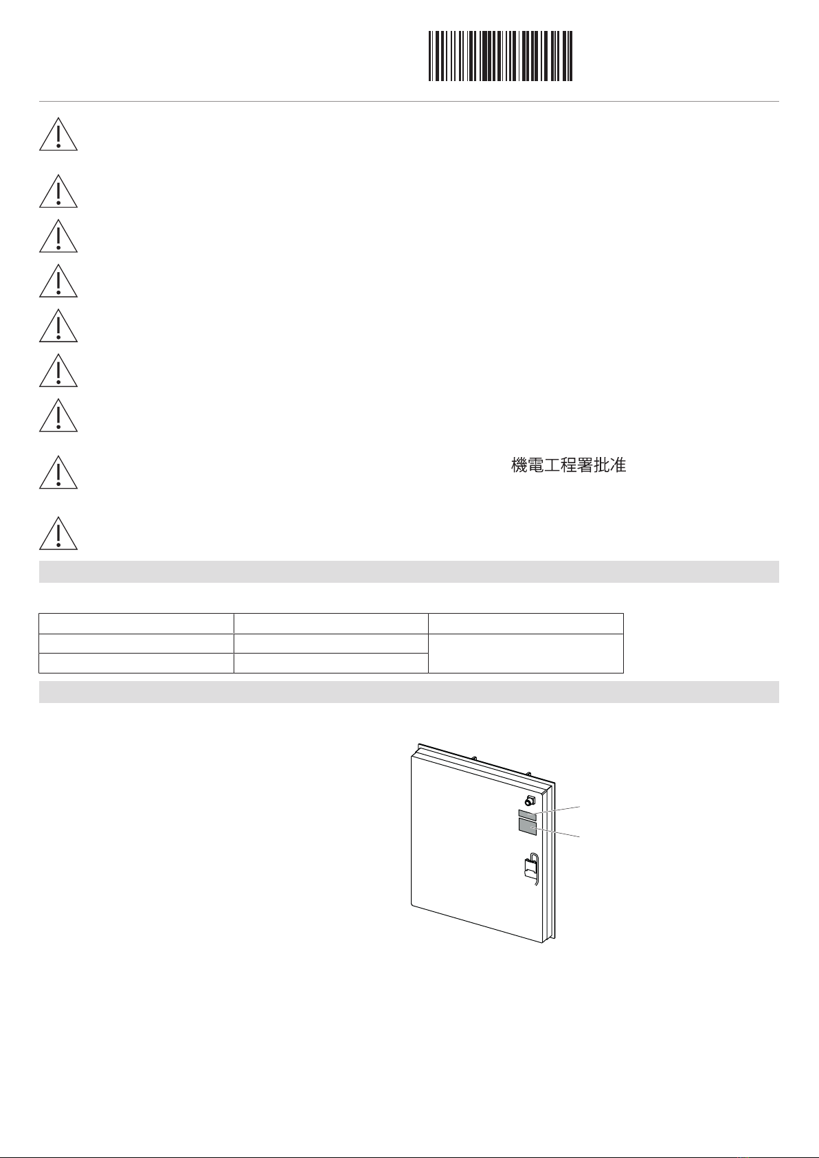
The connection cable has either a plug or three stranded wires.
Plug-in appliances must be connected to an easily accessible power socket.
Appliances with stranded wires must be connected by a qualified electrician via a junction box according to local regulations.
Installation pipe Distribution boxClamp
The mains plug must not be cut off.
Error message U400
Incorrect connection:
Pole conductor connected to connection terminal for neutral conductor or voltage too high.
▸Quickly disconnect the appliance from the mains!
Ventilation
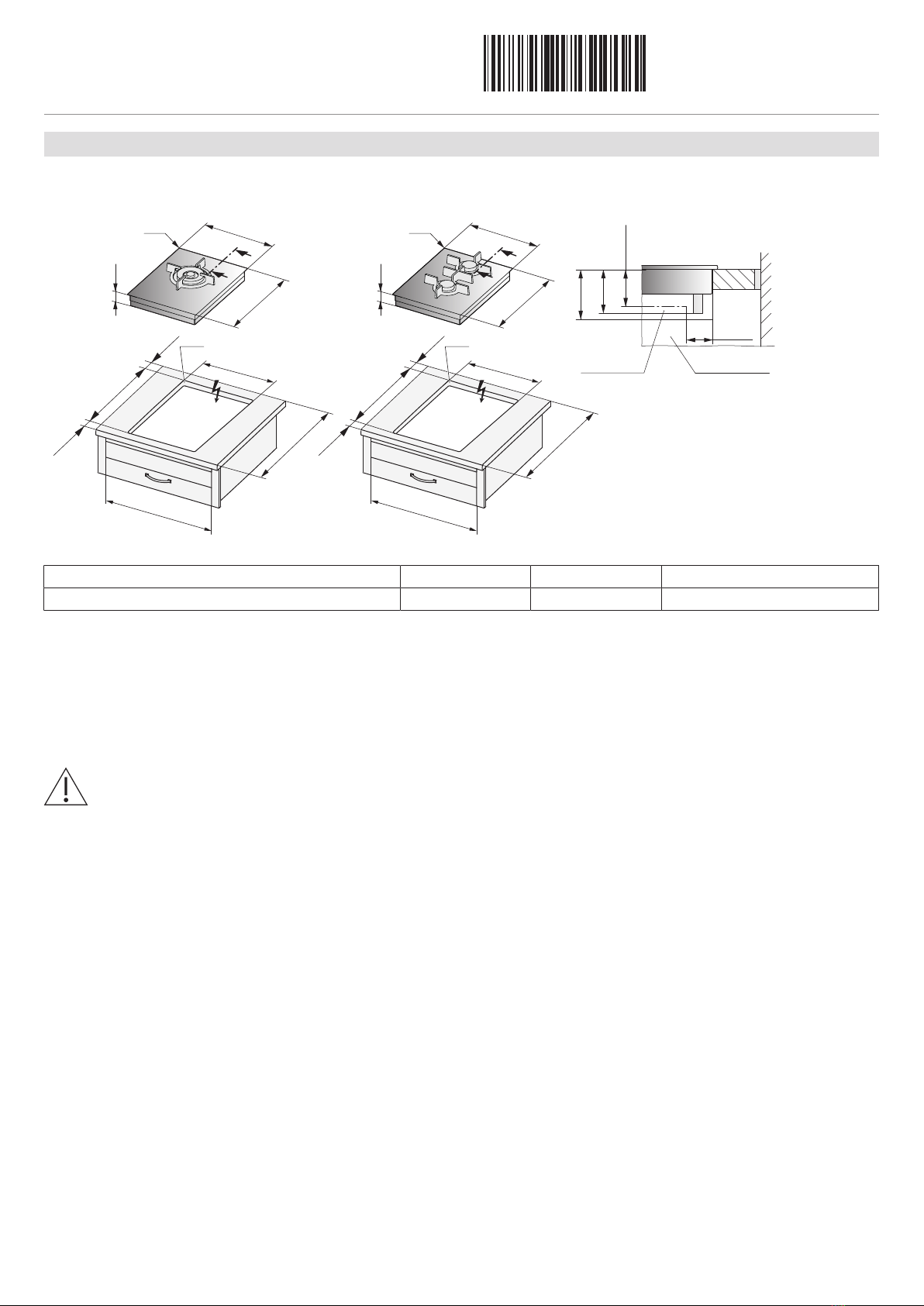
In order to guarantee minimum ventilation, a space of ≥20mm height is ne-
cessary beneath the appliance.
B
A
≥20
AThe rear panel of the base unit must be open around the work surface
cut-out to guarantee continuous air circulation through the ventilation
slits. The air must be drawn in from outside the cabinet and be able to
circulate freely from inside the cabinet to the hob. The lower plinth
must not be hermetically sealed. This can be achieved through a
shadow gap at the plinth panel or the use of a ventilation grille.
BAlternatively, a concealed fresh air supply can ensure air circulation in-
side the cabinet. In order that enough cold air can be drawn in, there
must be a continuous circulation of fresh air that extends outside the
cabinet. The air must be drawn in from outside the cabinet and be able
to circulate freely from inside the cabinet to the hob. The lower drawer
panel should therefore not hermetically seal the cabinet.
Installation instructions
Built-in variants of gas hob
Multi-Sliders GAS411/421
1037456-05
26/07/2023
1037456-05
6
Minimum distances and installation conditions
The distance from the appliance cut-out to the back wall must be ≥50mm and to the side walls ≥200mm. Parts such
as side walls and reinforcing strips which protrude into the installation space under the cooking zone must be made
of fire-resistant material.
The distance between the underside of the appliance tray and any part of the cabinet beneath that is made of com-
bustible material must be ≥20mm.
≥750
≥450
When a range hood is installed above the gas hob, the minimum distance given for
the particular range hood must be observed.
Furthermore, the minimum distances illustrated must be strictly complied with if a
lower value is stated for the range hood.
▪The worktop must be flat in order that it is sufficiently sealed against the ingress of
liquids.
▪In order to guarantee good ventilation, a space of at least 20mm in height is ne-
cessary beneath the appliance.
▸If the hobs are used at an altitude of over 2,000metres,a reduced performance
must be expected.
Gas connection
67
187 52.5
G ”
65
67
187
GAS411GSBZ GAS421GSBZ
▸The gas connection must be positioned so that the gas isolation valve and the supply connection point are accessible with the appli-
ance installed.
▸The gas connection must be positioned so that it does not get detrimentally hot during operation. In particular, the gas hose assem-
blies and the appliance’s connection fittings must be clear of hot exhaust gases (e.g. from an oven).
▸It must be ensured that the gas hose and the mains connection do not touch any hot parts of the appliance, otherwise the gas hose
and the mains cable could become damaged through heat.
▸A flexible connection lead (max. length 2 m) must be positioned so that it runs freely and does not come into contact with any mov-
able parts of the kitchen cabinets (e.g. a drawer).
▸No external pressure reducer is required for town gas if the connection pressure corresponds to the details on the identification
plate.
Gas type Test gas Connection pressure Remark
Hong Kong town gas G110 15 mbar No external pressure reducer is required.
Installation instructions
Built-in variants of gas hob
Multi-Sliders GAS411/421
1037456-05
26/07/2023
1037456-05
7
Connecting the appliance
The gas connection of the appliance has a G ½” cylindrical
thread with an internal conus.
Connection can be made by:
– A flexible gas connection pipe (must not exceed 2 m in
length)
Use approved gas tubing bearing the EMSD approval marking
(such as: EMSD APPROVAL GTXXXX)
for connection to appliance.
According to the Gas Safety Ordinance (Registration of Gas
Installers and Gas Contractors) Regulations, any gas installa-
tion work including the installation of appliances and connect-
ing tubing, must be undertaken by a registered gas installer
who is registered for that appropriate class and is employed
by a registered gas contractor.
G½” cylindrical thread
XX
internal conus
After the gas has been connected, leak and function testing must be carried out by a registered gas installer.

This manual suits for next models

5

Other V-ZUG Hob manuals

V-ZUG 005 Series User manual

V-ZUG

V-ZUG 005 Series User manual

V-ZUG Toptronic GK45TEBSC User manual

V-ZUG

V-ZUG Toptronic GK45TEBSC User manual

V-ZUG 1037885 User manual

V-ZUG

V-ZUG 1037885 User manual

V-ZUG GK11TIFKZ User manual

V-ZUG

V-ZUG GK11TIFKZ User manual

V-ZUG CookTop V2000 I604 User manual

V-ZUG

V-ZUG CookTop V2000 I604 User manual

V-ZUG GK46TIAKS User manual

V-ZUG

V-ZUG GK46TIAKS User manual

V-ZUG GK46TIAKS User manual

V-ZUG

V-ZUG GK46TIAKS User manual

V-ZUG GK47TIMAS Series User manual

V-ZUG

V-ZUG GK47TIMAS Series User manual

V-ZUG CookTop V4000 I704 User manual

V-ZUG

V-ZUG CookTop V4000 I704 User manual

V-ZUG GK16TIWSF User manual

V-ZUG

V-ZUG GK16TIWSF User manual

V-ZUG GAS641 User manual

V-ZUG

V-ZUG GAS641 User manual

V-ZUG GK11TTG User manual

V-ZUG

V-ZUG GK11TTG User manual

V-ZUG CookTopInduction V4000 CTI4T64 Series User manual

V-ZUG

V-ZUG CookTopInduction V4000 CTI4T64 Series User manual

V-ZUG GAS411 Series User manual

V-ZUG

V-ZUG GAS411 Series User manual

V-ZUG 31089 User manual

V-ZUG

V-ZUG 31089 User manual

V-ZUG GK26ID User manual

V-ZUG

V-ZUG GK26ID User manual

V-ZUG Toptronic User manual

V-ZUG

V-ZUG Toptronic User manual

V-ZUG GK36TIS User manual

V-ZUG

V-ZUG GK36TIS User manual

V-ZUG Home User manual

V-ZUG

V-ZUG Home User manual

V-ZUG GK46TIMXS User manual

V-ZUG

V-ZUG GK46TIMXS User manual

V-ZUG CombiCookTop V2000 I804 User manual

V-ZUG

V-ZUG CombiCookTop V2000 I804 User manual

V-ZUG CookTopInduktion V4000 User manual

V-ZUG

V-ZUG CookTopInduktion V4000 User manual

V-ZUG GK37TIMSF User manual

V-ZUG

V-ZUG GK37TIMSF User manual

V-ZUG GK21TI User manual

V-ZUG

V-ZUG GK21TI User manual

Popular Hob manuals by other brands

DeDietrich DTI1113X user manual

DeDietrich

DeDietrich DTI1113X user manual

ETNA A566ZT manual

ETNA

ETNA A566ZT manual

Lamona LAM1802 Instructions and installation

Lamona

Lamona LAM1802 Instructions and installation

elvita CIH9660S Instruction and installation manual

elvita

elvita CIH9660S Instruction and installation manual

Lincat IH21 Installation, operating and servicing instructions

Lincat

Lincat IH21 Installation, operating and servicing instructions

Silverline RS5322B01 user manual

Silverline

Silverline RS5322B01 user manual

Cylinda IHI7260 user manual

Cylinda

Cylinda IHI7260 user manual

Pelgrim CK1064KR manual

Pelgrim

Pelgrim CK1064KR manual

ETNA KI680 Instructions for use

ETNA

ETNA KI680 Instructions for use

Tricity Bendix TBC 650 F Operating & installation instructions

Tricity Bendix

Tricity Bendix TBC 650 F Operating & installation instructions

Karinear KNC-D22058 Instruction manual / installation manual

Karinear

Karinear KNC-D22058 Instruction manual / installation manual

Indesit KJ6G2/R user manual

Indesit

Indesit KJ6G2/R user manual

Elba 74-200 SS manual

Elba

Elba 74-200 SS manual

Electrolux EGT6242 user manual

Electrolux

Electrolux EGT6242 user manual

BORETTI BIKP-91 operating instructions

BORETTI

BORETTI BIKP-91 operating instructions

Gorenje IQook Instructions for use, installation, and connection

Gorenje

Gorenje IQook Instructions for use, installation, and connection

Electrolux EHF6241FMK user manual

Electrolux

Electrolux EHF6241FMK user manual

AEG CERAMIC HOB 6010 K operating instructions

AEG

AEG CERAMIC HOB 6010 K operating instructions

manuals.online logo
manuals.online logoBrands
  • About & Mission
  • Contact us
  • Privacy Policy
  • Terms and Conditions

Copyright 2025 Manuals.Online. All Rights Reserved.