V-ZUG WT-ATLWPZ 958 User manual

Installationsanleitung
Komfortschublade
für Wäschetrockner
J283.050-3
13.8.09 ITH
1
Diese Installationsanleitung gilt für die Modelle: 283–286, 296, 954–959
* Material wird beim Wäschetrockner nicht benötigt.
Sockelblende W5.2014 (für optische Anpassung).
Vorbereitung
1. Netzstecker ausstecken oder Wandschalter ausschalten.
Installation
2. Gerät aus der Nische hervorziehen und die Installations-
platte vom Boden entfernen; diese wird nicht mehr
benötigt.
3. Komfortschublade 1am gleichen Standort platzieren
und Schublade 2entfernen, dazu die schwarzen
Schienenfedern 4seitlich hochdrücken.
4. Installationsschablone 3zwischen den vorderen
Verstellfüssen mittig auf den Boden kleben.
Die Installation darf nur durch fachkundiges Personal ausgeführt werden. Alle Arbeitsschritte müssen der Reihe nach
vollständig ausgeführt und kontrolliert werden.
Gültigkeitsbereich
Allgemeine Hinweise
Eine einwandfreie Reparatur kann nur gewährleistet werden, wenn jederzeit eine zerstörungsfreie Deinstallation des komplet-
ten Gerätes möglich ist.
Mitgeliefertes Installationszubehör
Bezeichnung Stückzahl Bezeichnung Stückzahl
Bodenfixierteller inkl. Doppelkleberondellen 2 U-Scheiben St EZN * 4
Nylondübel Delta Gr. 6 2 Kombischlüssel 19 mm 1
Senkholzschrauben 5 × 30 2 Kombischlüssel 27 mm * 1
Installationsschablone für Bodenfixierteller 1 6-kt Rohrschlüssel * 1
6-kt Muttern 0,8D St EZN * 4 In-6kt Schlüssel * 1
Optionen
Abmessungen
Installation
Die Hebe- und Platzierarbeiten des Wärmepumpentrockners müssen von 2 Personen ausgeführt werden. Der Wärmepumpen-
trockner sollte während der Installation nicht über 45° aus der Vertikalen geneigt werden, da das Gerät sonst vor der Inbetrieb-
nahme ca. 2 Stunden in der betriebsüblichen Position stehen gelassen werden muss.
43021
~340
550
595
Ansicht von oben
4
2
1
3

Installationsanleitung
Komfortschublade
für Wäschetrockner
J283.050-3
13.8.09 ITH
2
5. Bodenfixierteller ankleben
AAbdeckfolie von Fixiertellern abziehen.
AKomfortschublade und Gerät vorne anheben und zum Aufkleben der Fixierteller wegschieben.
AKlebestelle mit Reinbenzin oder Aceton reinigen.
ADie Befestigungsposition von der Installationsschablone 3übernehmen und die Fixierteller auf den
Boden kleben.
Bodenfixierteller anschrauben
AKomfortschublade zum Bohren der Fixierteller wegschieben.
ADie Mitte der Löcher mit Hilfe der Installationsschablone 3anzeichnen.
ALöcher ø 6 mm bohren und Dübel einsetzen. Fixierteller anschrauben. Mittels exzentrischem Loch
im Fixierteller kann eine Ungenauigkeit beim Bohren ausgeglichen werden.
6. Die Komfortschublade aus der Nische hervorziehen und die Installationsschablone entfernen.
7. Verstellfüsse von Hand herausdrehen, bis die gefaltete
Installationsschablone 3an allen 4 Ecken unter das
Gerät 5passt (siehe Detail X).
8. Gerät hochheben und die vorderen Verstellfüsse von oben in
das Abschlussprofil 6der Komfortschublade schieben.
9. Hintere Verstellfüsse in Positionierteller 7 absetzen. Falls
notwendig, Gerät nivellieren, damit sich ein gleichmässiger
Spalt zwischen Gerät und Komfortschublade von 2 mm ergibt.
10. Gerät und Komfortschublade platzieren.
11. Schublade einsetzen und soweit einschieben, bis Schienen-
federn wieder einrasten.
12. Sockelblende W5.2014, falls vorhanden, installieren.
Hilfsmittel: Kombi-Schlüssel 19 mm 8(mitgeliefert) und Wasserwaage 9
Hintere Nivellierfüsse
AKontermutter 10 lösen.
AKomfortschublade – durch Drehen des Fusses von Hand – lotrecht ausrichten.
AKontermutter fest anziehen.
Vordere Nivellierfüsse
AGerät in Bodenfixierteller stellen.
AKontermutter 10 lösen.
AKomfortschublade – durch Drehen des Fusses von Hand – lotrecht ausrichten.
– Komfortschublade und Gerät dürfen nicht wackeln.
AKontermutter fest anziehen.
Um eine Beschädigung der Komfortschublade zu vermeiden, müssen die Verstellfüsse vor dem Aufeinanderstellen mit Hilfe
der Installationsschablone 3auf die korrekte Höhe von 22 mm eingestellt werden.
Nivellieren
Für einen einwandfreien Betrieb muss die Komfortschublade mit dem Gerät lotrecht mit allen Füssen fest auf dem Boden
stehen und die Kontermuttern 10 müssen fest angezogen sein.
3
==
5
7
3
22
2
6
Detail X
8
9
10

Notice d’installation
Tiroir confort
pour sèche-linge
J283.050-3
13.8.09 ITH
3
Cette notice d’installation est valable pour les modèles: 283–286, 296, 954–959
* Cet outillage n’est pas utilisé pour le sèche-linge.
Cache de socle W5.2014 (pour adaptation optique).
Préparation
1. Débrancher la fiche d’alimentation ou déclencher l’interrupteur mural.
Installation
2. Tirer l’appareil de la niche et retirer la plaque
d’installation du sol; celle-ci n’a plus lieu d’être.
3. Placer le tiroir confort 1au même emplacement et
retirer le tiroir 2. Pour ce faire, presser vers le haut les
languettes noires 4de rails situées sur le côté.
4. Coller le gabarit d’installation 3de façon centrée sur
le sol entre les pieds d’ajustage avant.
L’installation doit impérativement être exécutée par un personnel qualifié. Toutes les étapes doivent être réalisées en intégralité
dans l’ordre et contrôlées.
Domaine de validité
Indications générales
Une réparation impeccable ne pourra être effectuée que si l’appareil complet peut être démonté non destructif à tout moment.
Supplied installation accessories
Désignation Unité Désignation Unité
Disques de fixation au sol, rondelles adhésives double face 2 Rondelles St EZN * 4
Chevillon Nylon Delta taille 6 2 Clé combinée 19 mm 1
Vis à bois à tête conique 5 × 30 2 Clé combinée 27 mm * 1
Gabarit d’installation pour disques de fixation au sol 1 Clé à tube hexagonale * 1
Ecrous hexagonaux 0,8D St EZN * 4 Clé à six pans creux * 1
Options
Dimensions
Installation
Les opérations de levage et de placement du sèche-linge à pompe à chaleur doivent être exécutées par 2 personnes. Pendant
l’installation, le sèche-linge à pompe à chaleur ne doit pas être penché de plus de 45° par rapport à la verticale, faute de quoi
l’appareil doit être laissé au repos pendant env. 2 heures dans la position d’utilisation courante avant qu’il soit possible de
procéder à la mise en service.
43021
~340
550
595
Vue de dessus
4
2
1
3

Notice d’installation
Tiroir confort
pour sèche-linge
J283.050-3
13.8.09 ITH
4
5. Coller les disques de fixation au sol
ARetirer le film protecteur des disques de fixation.
ASoulever le tiroir confort et l’appareil à l’avant et écarter pour coller les disques de fixation.
ANettoyer l’emplacement de collage avec de l’essence pure ou de l’acétone.
AReprendre la position de fixation du gabarit d’installation 3et coller les disques de fixation sur le sol.
Visser les disques de fixation au sol
AEcarter le tiroir confort pour percer les disques de fixation.
AEsquisser le centre des trous à l’aide du gabarit d’installation 3.
APercer des trous de ø 6 mm et mettre en place les chevilles. Visser les disques de fixation. Un trou
excentrique dans le disque de fixation permet de compenser un perçage imprécis.
6. Tirer de la niche le tiroir confort et retirer le gabarit d’installation.
7. Dévisser les pieds d’ajustage à la main jusqu’à ce que le
gabarit d’installation plié 3aille sous l’appareil 5aux 4
angles (voir détail X).
8. Soulever l’appareil et les pieds d’ajustage avant par le
haut et introduire le profilé de fermeture 6du tiroir confort.
9. Placer les pieds d’ajustage arrière dans les disques de
positionnement 7. Si nécessaire, procéder au nivellement
de l’appareil afin d’obtenir une fente régulière de 2 mm
entre l’appareil et le tiroir confort.
10. Mettre en place l’appareil et le tiroir confort.
11. Mettre en place le tiroir et l’introduire jusqu’à ce que les
languettes de rails s’enclenchent à nouveau.
12. Installer le cache de socle W5.2014, si existant.
Aide: clé combinée 19 mm 8(fournie) et niveau à bulle d’air 9
Pieds arrière de nivellement
ADesserrer le contre-écrou 10.
AMettre le tiroir confort d’aplomb – en tournant le pied à la main.
ASerrer à fond le contre-écrou.
Pieds avant de nivellement
APlacer l’appareil dans les disques de fixation au sol.
ADesserrer le contre-écrou 10.
AMettre le tiroir confort d’aplomb – en tournant le pied à la main.
– Le tiroir confort et l’appareil ne doivent pas vaciller.
ASerrer à fond le contre-écrou.
Pour éviter un endommagement du tiroir confort, les pieds d’ajustage doivent être réglés à la hauteur correcte de 22 mm à
l’aide du gabarit d’installation 3avant la superposition.
Nivellement
Pour un fonctionnement irréprochable, le tiroir confort doit être solidement d’aplomb avec l’appareil et ses pieds et les contre-
écrous 10 doivent être vissés fermement.
3
==
5
7
3
22
2
6
Détail X
8
9
10

Istruzioni d’installazione
Cassetto comfort
per asciugatrici
J283.050-3
13.8.09 ITH
5
Queste Istruzioni d’installazione riguardano i modelli: 283–286, 296, 954–959
* Per l’asciugatrice non è necessario alcun materiale.
Pannello dello zoccolo W5.2014 (per rifinitura ottica).
Preparazione
1. Sfilare la spina dalla presa della rete elettrica o spegnere l’interruttore a parete.
Installazione
2. Estrarre l’apparecchio dalla nicchia e togliere la piastra
d’installazione dal pavimento. Questa non serve più.
3. Posizionare il cassetto comfort 1presso lo stesso
posto e togliere il cassetto 2, a questo scopo premere
lateralmente verso l’alto le molle delle guide nere 4.
4. Incollare sul pavimento la sagoma d’installazione 3
centrandola tra i piedini di regolazione anteriori.
L’installazione può essere eseguita solo da personale specializzato. Tutte le sequenze di lavoro devono essere eseguite
completamente una dopo l’altra e controllate.
Campo di validità
Indicazioni generali
Una riparazione impeccabile potrà essere effettuata soltanto se l’apparecchio completo può essere smontato non distruttivo in
qualsiasi momento.
Accessori d’installazione inclusi nella fornitura
Denominazione Quantità Denominazione Quantità
Piatto di fissaggio al pavimento incluse rondelle adesive doppie 2 Rondelle St EZN * 4
Tasselli di nailon Delta grandezza 6 2 Chiave combinata 19 mm 1
Vite da legno a testa svasata 5 × 30 2 Chiave combinata 27 mm * 1
Sagoma d’installazione per il piatto di fissaggio al pavimento 1 Chiave per tubi esagonale * 1
Dadi esagonali 0,8D St EZN * 4 Brugola * 1
Opzioni
Dimensioni
Installazione
I lavori di sollevamento e di collocazione dell’asciugatrice con pompa di calore devono essere eseguiti da 2 persone. Durante
l’installazione, l’asciugatrice con pompa di calore non dovrebbe essere inclinata di oltre 45° rispetto alla verticale, altrimenti
l’apparecchio dovrà essere tenuto fermo nella posizione d’esercizio usuale per ca. 2 ore prima della messa in esercizio.
43021
~340
550
595
Ansicht von oben
4
2
1
3

Istruzioni d’installazione
Cassetto comfort
per asciugatrici
J283.050-3
13.8.09 ITH
6
5. Incollare il piatto di fissaggio al pavimento
AStaccare il foglio di protezione dai piatti di fissaggio.
ASollevare il cassetto comfort e l’apparecchio dal davanti e spostarlo per permettere l’incollaggio dei
piatti di fissaggio.
APulire il posto d’incollaggio con benzina bianca o con acetone.
ARiprendere la posizione di fissaggio dalla sagoma d’installazione 3e incollare i piatti di fissaggio al
pavimento.
Avvitare i piatti di fissaggio al pavimento
APer perforare i piatti di fissaggio, spostare il cassetto comfort.
ATracciare il centro dei fori servendosi della sagoma d’installazione 3.
APerforare i fori ø 6 mm e inserire i tasselli. Avvitare il piatto di fissaggio. Il foro eccentrico del piatto
di fissaggio permette di compensare eventuali sprecisioni della perforazione.
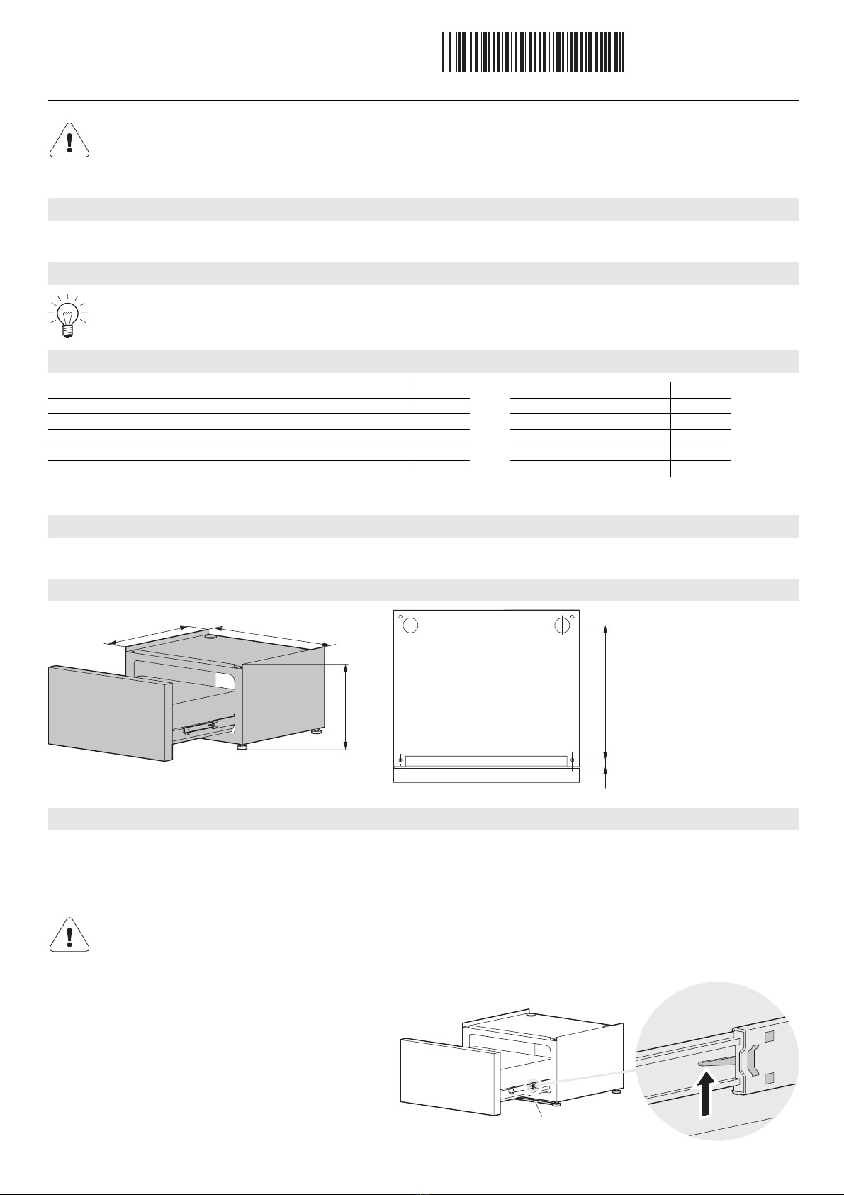
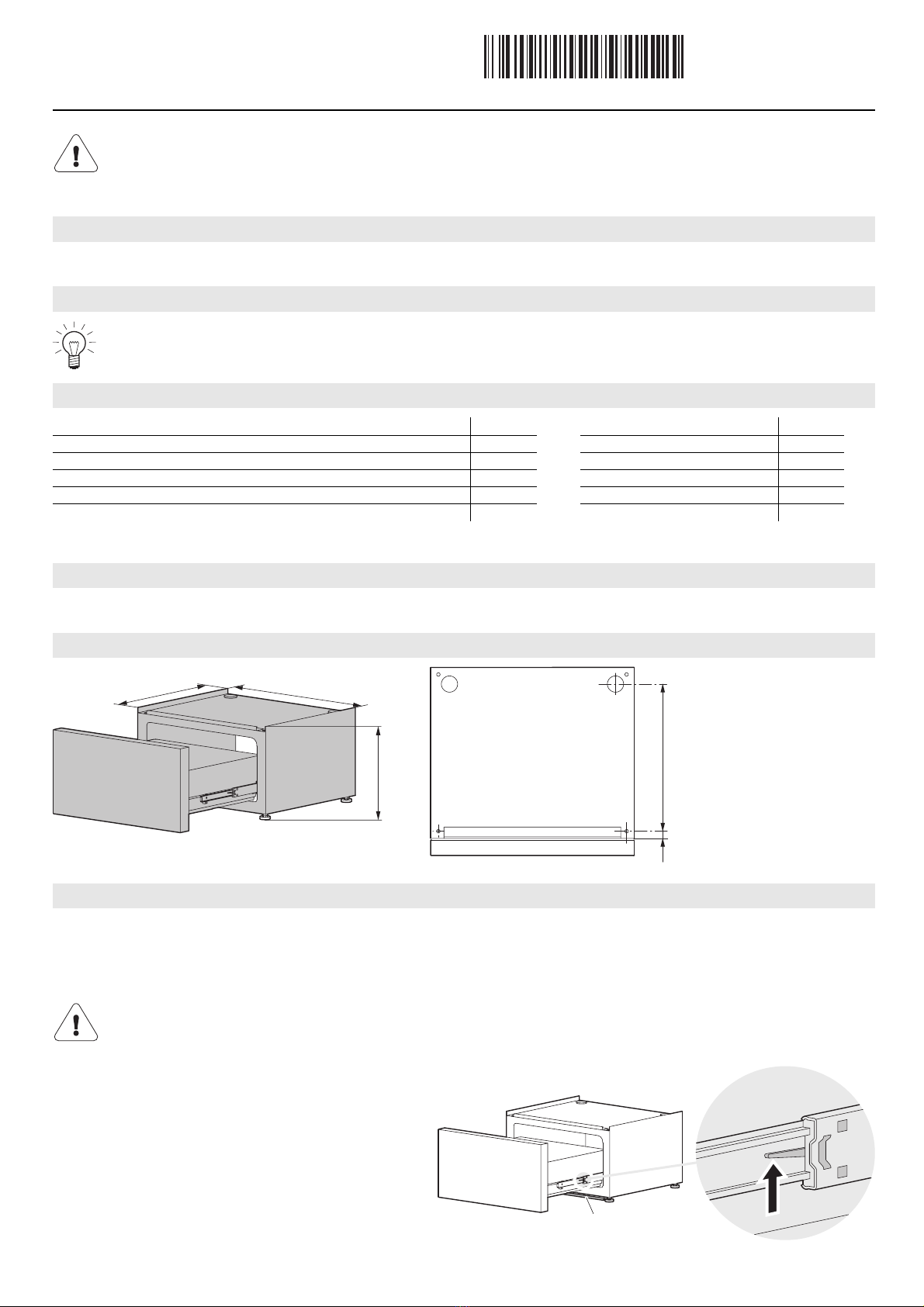
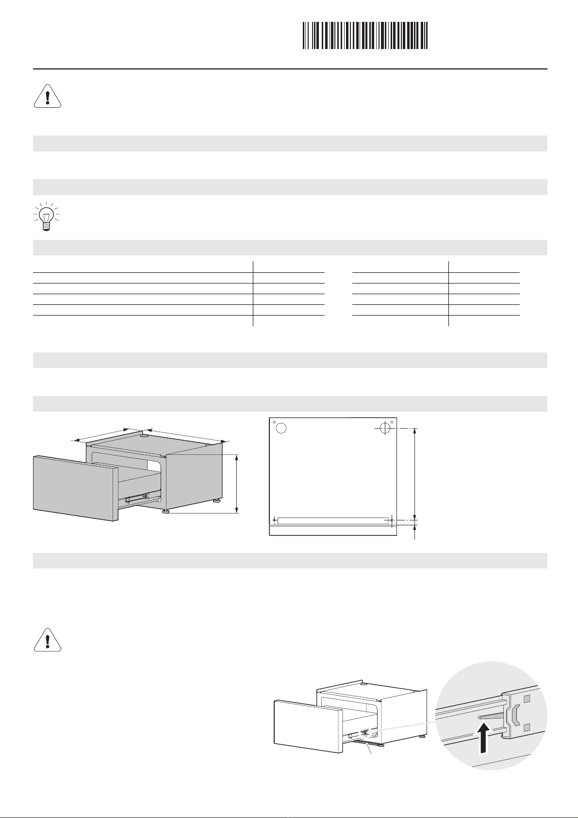
6. Estrarre il cassetto comfort dalla nicchia e togliere la sagoma d’installazione.
7. Svitare i piedini di regolazione manualmente quanto basta
affinché la sagoma d’installazione ripiegata 3si adatti presso
tutti i 4 angoli sotto l’apparecchio 5(vedere dettaglio X).
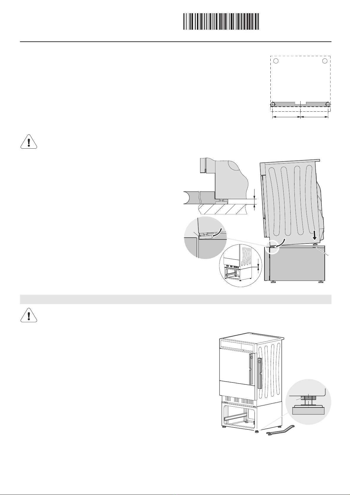
8. Sollevare l’apparecchio e, procedendo dall’alto, infilare i
piedini di regolazione anteriori dall’alto nel profilo di
collegamento 6del cassetto comfort.
9. Appoggiare i piedini di regolazione posteriori nei piatti di
posizionamento 7. Se necessario, livellare l’apparecchio, fino
a creare una fessura omogenea di 2 mm tra l’apparecchio e il
cassetto comfort.
10. Posizionare l’apparecchio e il cassetto comfort.
11. Inserire il cassetto e infilarlo fino a quando le molle della
guida agganciano nuovamente.
12. Installare il pannello dello zoccolo W5.2014, se esiste.
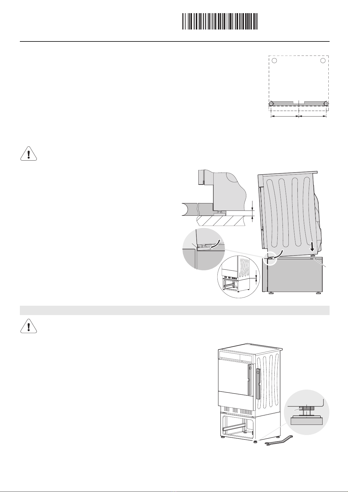
Mezzi ausiliari: Chiave combinata 19 mm 8(compresa nella fornitura) e livella a bolla
d’aria 9
Piedini di livellamento posteriori
AAllentare il controdado 10.
AAllineare verticalmente il cassetto comfort, girando il piedino manualmente.
AStringere saldamente il controdado.
Piedini di livellamento anteriori
APorre l’apparecchio nel piatto di fissaggio al pavimento.
AAllentare il controdado 10.
AAllineare verticalmente il cassetto comfort, girando il piedino manualmente.
– Il cassetto comfort e l’apparecchio non devono traballare.
AStringere saldamente il controdado.
Per evitare di danneggiare il cassetto comfort, prima di sovrapporre gli apparecchi occorre regolare i piedini di regolazione con
l’aiuto della sagoma d’installazione 3all’altezza esatta di 22 mm.
Livellare
Per un esercizio ineccepibile, il cassetto comfort deve appoggiare con tutti i piedini saldamente e perpendicolarmente sul
terreno e i controdadi 10 devono essere ben stretti.
3
==
5
7
3
22
2
6
Dettaglio X
8
9
10

Installation instructions
Convenient storage drawer
for tumble driers
J283.050-3
13.8.09 ITH
7
These installation instructions apply to the models: 283–286, 296, 954–959
* Material is not required with the tumble drier.
Plinth W5.2014 (for visual adaptation).
Preparation
1. Unplug the mains connection plug or switch off at the wall switch.
Installation
2. Pull the appliance out of the niche and remove the
installation plate from the floor; this is no longer required.
3. Place the convenient storage drawer 1on the same spot
and remove the drawer 2by lifting the black rail springs 4
at the side.
4. Stick the installation template 3to the floor centrally
between the adjustable feet.
The appliance should be installed by qualified personnel only. Each step must be carried out and checked in full in the order
specified.
Validity
General notes
A full repair can only be guaranteed providing the non-destructive deinstallation of the complete appliance is possible at any
time.
Installation accessories included
Designation Number of items Designation Number of items
Floor mounting plate incl. double sided adhesive discs 2 U-washers St EZN * 4
Nylon plug Delta size 6 2 Combi spanner 19 mm 1
Countersunk head wood screws 5 × 30 2 Combi spanner 27 mm * 1
Installation template for floor mounting plate 1 Hexagon box spanner * 1
Hexagon nuts 0.8D St EZN * 4 Allen key * 1
Options
Dimensions
Installation
Lifting and positioning of the tumble drier must be carried out by 2 persons. During installation the tumble drier must not be
tilted from the vertical by more than 45°, otherwise the appliance will have to be left standing in its normal operating position
for about 2 hours prior to startup.
43021
~340
550
595
Top view
4
2
1
3

Installation instructions
Convenient storage drawer
for tumble driers
J283.050-3
13.8.09 ITH
8
5. Affixing the floor mounting plates
ARemove the protective film from the mounting plates.
ALift up the convenient storage drawer and the appliance at the front and move it aside in order to
stick the mounting plates in position.
AClean the adhesive zone with pure benzine or acetone.
ATaking the fixing position from the installation template 3, stick the mounting plates to the floor.
Screwing the floor mounting plates
AMove the convenient storage drawer aside to drill the mounting plates.
AMark the centre of the holes, using the installation template 3.
ADrill ø 6 mm holes and insert plugs. Screw the mounting plate in place. Drilling inaccuracies can
be compensated by means of the eccentric hole in the mounting plate.
6. Pull the convenient storage drawer out of the niche and remove the installation template.
7. Unscrew the adjuster feet by hand until the folded installation
template 3fits under the appliance 5at all 4 corners (see
detail X).
8. Lift the appliance and push the front adjuster feet from above
into the finished profile 6of the convenient storage drawer.
9. Place the rear adjuster feet in the positioning plate 7. Where
necessary, level the appliance to obtain a uniform gap of 2 mm
between the appliance and the convenient storage drawer.
10. Place appliance and convenient storage drawer in position.
11. Insert the drawer and slide in until the rail springs re-engage.
12. Mount plinth W5.2014 where applicable.
Tools: Combi spanner 19 mm 8(supplied) and spirit level 9
Rear adjuster feet
ALoosen lock nuts 10.
AAlign convenient storage drawer vertically by turning the foot by hand.
ATighten the lock nuts firmly.
Front adjuster feet
APlace the appliance in the floor mounting plate.
ALoosen lock nuts 10.
AAlign convenient storage drawer vertically by turning the foot by hand.
– Convenient storage drawer and appliance must be absolutely stable.
ATighten the lock nuts.
To avoid damaging the convenient storage drawer, set the adjuster feet to the correct height of 22 mm, using the installation
template 3, before placing the appliance in position.
Levelling
For fault-free operation the convenient storage drawer must stand perpendicular to the appliance with all feet firmly on the
ground and the lock nuts 10 must be firmly tightened.
3
==
5
7
3
22
2
6
Detail X
8
9
10
Other manuals for WT-ATLWPZ 958
1
This manual suits for next models
10
Table of contents
Languages:
Other V-ZUG Laundry Accessories manuals
Popular Laundry Accessories manuals by other brands

GE
GE Profile WE25M46 installation instructions

BetterLiving
BetterLiving Compact Clothes Line Setup and operation

Maytag
Maytag 12001736 instruction sheet

Whirlpool
Whirlpool 279827 Installation and wiring instructions

Amana
Amana LAUNDRY WORKSURFACE Use and care guide

Simoniz
Simoniz 039-8708-0 Use and care guide