VACGEN OMNIAX Series Manual

Page 1 of 35
[email protected] www.vacgen.com +44 (0) 1424 856 333
Operating and Maintenance Handbook
OMNIAX TRANSLATOR SERIES
Copyright Notice 2015 by VACGEN. All rights reserved. Information contained in this handbook is
subject to change without notice and does not represent a commitment on the part of VACGEN. No
part of this document may be copied or distributed, transmitted, transcribed, stored in a retrieval
system or translated into any human or computer language, in any form or by any means, electronic,
mechanical, magnetic, optical, manual or otherwise or disclosed to third parties without the express
written permission of VACGEN, Maunsell Road, Castleham Industrial Estate, St, Leonards on Sea,
East Sussex, TN38 9NN, UK

Page 2 of 35
[email protected] www.vacgen.com +44 (0) 1424 856 333
WARRANTY
1. Subject to fair wear and tear and the due, observance of any installation user, storage, operating or
maintenance instructions the Seller undertakes to replace or, at its option repair free of charge to the
purchaser, any goods which the purchaser can establish are defective by reason of defective
workmanship or materials which are returned to the Seller, carriage paid, within 12 months of the date
of dispatch by the Seller. In the event, however, that the Seller supplies spare parts either direct, or
that are fitted or installed or replaced by the Sellers' service center such spare parts will be subject to
a warranty period of six months only.
2. The Purchaser cannot return any product for warranty repair without the prior approval of VACGEN
and the issue of a Goods Return Number (GRN). This shall be obtained by contacting the service
center at VACGEN. All returned products must be accompanied by a completed Declaration of
Contamination form. Customers must, in the first instance, contact the local selling agent.
3. We reserve the right to decline to service equipment, we consider is in any way hazardous until a
clearance or safety certificate, in a form satisfactory to VACGEN, has been completed and returned
by the customer.
REPAIR
The following additional terms and conditions apply in the event that the customer elects to use the
services of VACGEN workshop on a chargeable basis.
1. At its own cost the customer shall dispatch the equipment to the workshop, carriage paid, suitably
packaged, protected and insured, bearing, a Goods Return Number (GRN)and a completed
Declaration of Contamination certificate obtained from VACGEN in advance of shipment.
2. During the period that the equipment is on VACGEN premises, VACGEN will insure the equipment
against all risks.
3. Vacuum Generator will provide an acknowledgement of the receipt together with an estimate of the
repair charges. Such estimates are carried out on a visual basis and are therefore intended as a
guide only. Formal fixed price repair quotations are available and involve the disassembly of the
equipment to determine the full extent of
the work necessary to restore the equipment to an acceptable standard. In the event that the
customer chooses not to proceed with the repair VACGEN will make a charge to cover this
examination effort.
Note:
The above are extracts from VACGEN Conditions of sale. Complete copies can be obtained from:
VACGEN, Maunsell Road, Castleham Industrial Estate St. Leonards on Sea, East Sussex, TN38
9NN, United Kingdom.

Page 3 of 35
[email protected] www.vacgen.com +44 (0) 1424 856 333
1. INTRODUCTION
1.1 HEALTH AND SAFETY INFORMATION
This equipment is a component for use with vacuum systems. Whilst every effort has been made to
eliminate hazards, its safe use is also dependant on the system to which it will be connected.
The owner of the equipment must ensure that all users are aware of the Health and Safety
information contained in this handbook. If the equipment is sold or passed to another owner, this
handbook must be included with the equipment.. If in doubt contact VACGEN.
Warning: This equipment must be installed by qualified personnel.
Warning: It is the responsibility of the user to consider the safety requirements of hazardous
materials used with this equipment and the consequence of any leakage, however caused. Consider
possible reactions with materials of construction. Any equipment returned to VACGEN must have the
correct Declaration of Contamination securely fastened to the outside of the packaging.
Warning: Harmful gases may be evolved if this equipment is heated to temperatures above the
maximum specified bakeout temperature.
Warning: Lubricants used in this assembly may cause irritation to sensitive skin. Wear protective
clothing.
Warning: Where cryogenic liquids are used with the equipment, it is the responsibility of the user to
ensure that the correct safety precautions are taken when handling and storing these materials.
Warning: Safe disposal of the equipment is the responsibility of the user.
Warning: It is the responsibility of the user to fit emergency stops to automated equipment.
Warning: Keep clear of moving pans.
Warning: Do not use this equipment with positive internal pressure above the specified maximum.
Warning: Some equipment may develop extreme hot or cold surfaces. Wear protective clothing.
Warning: Equipment must be fully earthed to prevent dangerous electrostatic charge build-up.

Page 4 of 35
[email protected] www.vacgen.com +44 (0) 1424 856 333
1.2 GENERAL
The OMNIAX is a high precision, high rigidity, UHV specimen translator of modular construction,
suitable for a range of X, Y and Z motions. The modular construction means that the specification can
be upgraded or modified by the addition or replacement of well defined modules.
The OMMAX has been designed for ease of use and most functions should be straightforward. This
handbook outlines the general considerations for installation, use and maintenance.
Most manipulator configurations utilising the OMNIAX translator will also use drives and
instrumentation that are not included in this handbook. This handbook should therefore be read in
conjunction with documentation supplied for the other equipment.
1.3 SPECIFICATIONS
Support tubes:
Omniax translators can be supplied with either 50mm bore (54mm OD) or
29 mm bore (32mm OD) options.
Positional control:
X, Y: Micrometer or stepper motor
Z: Handwheel or stepper motor
Pressure range:
1 bar to 10-11mbar
Operating temperature:
-20oC to +55oC
Baking temperature:
230oC (motors, instrument cables and other non-bakeable ancillary
hardware removed.)
Standard base flange:
NW100CF (151.5mm (6") OD) or NW150CF ( 202.5mm (8") OD).
Traveling flange:
NW63CF (114mm (4.5") OD)
Environment:
This equipment is intended for use in clean, dry environments. For use in other conditions, please
contact VACGEN Technical Sales.
Materials of Construction:
All units are manufactured mainly from austenitic stainless steel or aluminum alloy. Stainless steel is
used for parts that form the vacuum envelope. Demountable vacuum seals use copper gaskets.
Bearings surfaces may include martensitic stainless steel, bronze alloys and PTFE polymer
compounds. Atmosphere side bearing surfaces are normally lubricated with high temperature
'Carbaflo' grease or fluid. The micrometers are conditioned for bakeout to 230oC. Motors contain non-
bakeable plastic and must be removed for bakeout. Atmosphere side fixing screw threads are treated
with ZTL thread lubricant.

Page 5 of 35
[email protected] www.vacgen.com +44 (0) 1424 856 333
1.4 BASIC DIMENSIONS
Figure 1 - Basic dimensions and layout of Omniax

Page 6 of 35
[email protected] www.vacgen.com +44 (0) 1424 856 333
1.5 Z MOTION
Z Travel
A1
C
Weight
(1) (kg)
100
184 to 284
374
40
200
186 to 386
477
42
400
186 to 586
677
46
600
229 to 829
920
52
800
273 to l073
1164
56
1000
317 to 1317
1408
61
Caution: these limits are not protected by limit stops or switches
Notes
(1) The weight of the Omniax
manipulator will vary depending on
configuration details.
(2) Motor specifications assume the
use of a VACGEN motor
drive-controller.
(3) Repeatability assumes the drive
is always from the same direction,
and at constant temperature
conditions.
(4) The T208 XY stage can only be
used with the 028mm ID support
tube. If used with the 50mm ID
support tube, travel
must be limited to ±15mm
vectorial.
(5) The XY travel is limited by the
vectorial sum of the X and Y
movement, i.e: (X2+Y2). Some
examples are shown in the table
below.
Examples of vectorial sums
For ±1 2.5mm; Xmax = 12.5 10 8.8 5 3
(X2+Y2)=12.5 Ymax = 0 7.5 8.8 11.4 12.1
For ±25mm; Xmax = 25 20 17.6 12 3
(X2+Y2)=25.0 Ymax = 0 15 17.6 21.9 24.8 1
Z-SLIDE SPECIFICATIONS:
Resolution 10 microns manual
0.5 microns motorised (2)
Repeatability (3) 10 microns manual (3)
1 micron motorised (2)(3)
Maximum Speed 4mm/s motorised (2)
1.6 XY MOTION
Basic code Bellows
XY Travel of XY stage A2 bore OD
±0 T000 80 95
±12.5(5) T108 135 85
±25.0(4)(5) T208(4) 167 85(4)
±25.0(1) T211 175 108
XY STAGE SPECIFICATIONS:
Resolution 5 microns manual
0.5 microns motorised (2)
Repeatability (3) 5 microns manual (3)
1 micron motorised (2)(3)
Maximum Speed 4mm/s motorised (2)

Page 7 of 35
[email protected] www.vacgen.com +44 (0) 1424 856 333
2. INSTALLATION
2.1 IMPORTANT - READ BEFORE UNPACKING
Warning: Take care when lifting the unit that the weight and position do not exceed comfortable
limits. When installing the device make sure that it is adequately supported at all times.
Warning: Do not operate any of the controls until the XY shipping pin and all transit items have been
removed. Failure to do so may result in serious damage to both the translator and vacuum system.
a. With two or more persons, lift out the translator using the lifting handles. DO NOT use bellows,
drives or instrumentation as lifting points. Take care not to hit or damage any protruding parts of the
translator. Lie the translator on its back or stand vertically on the attached frame.
b. Carefully inspect the translator for visual signs of damage. The packaging is designed to with
stand shock and vibration but some of the fixing screws may become loose, more especially with air
freight shipment. All parts should be secure and there should be no 'play' in any of the movements. All
screws should be securely fastened but not excessively tight.
c. Any damage in transit should be, reported to the carrier and to VACGEN at Hastings, or your local
agent, within three days. Retain the packaging.
d. Remove the shipping pin and all transit items before operating any of the controls.
2.2 INSTALLATION GUIDELINES
Warning: This equipment must be installed by qualified personnel.
Warning: It is the responsibility of the user to consider the safety requirements of hazardous
materials used with this equipment and the consequence of any leakage, however caused. Consider
possible reactions with materials of construction. Any equipment returned to VACGEN must have the
correct Declaration of Contamination securely Fastened to the outside of the packaging.
Warning: Lubricants used in this assembly may cause irritation to sensitive skin. Wear protective
clothing.
Warning: It is the responsibility of the user to fit emergency stops to automated equipment.
Warning: Equipment must be fully earthed to prevent dangerous electrostatic charge buildup.
a. The OMNIAX will operate when mounted in any orientation. However, because of the weight of the
translator, very careful consideration must be given to ensuring that the level of stress exerted onto
the chamber and within the translator itself is as low as possible. Where practical the translator should
be vertically mounted. For horizontally mounted units, special mounting arrangements are required.
See Appendix A.
b. It is not possible to generalize on mounting arrangements for other orientations. Any supporting
cradle must allow for X & Y motions as well as supporting the weight of the frame. Also the centre of
gravity will vary as the Z motion is used. Normally this is not significant but must be considered where
very long Z travels (800mm and greater) are used or where heavy equipment is being moved on the Z
slide.
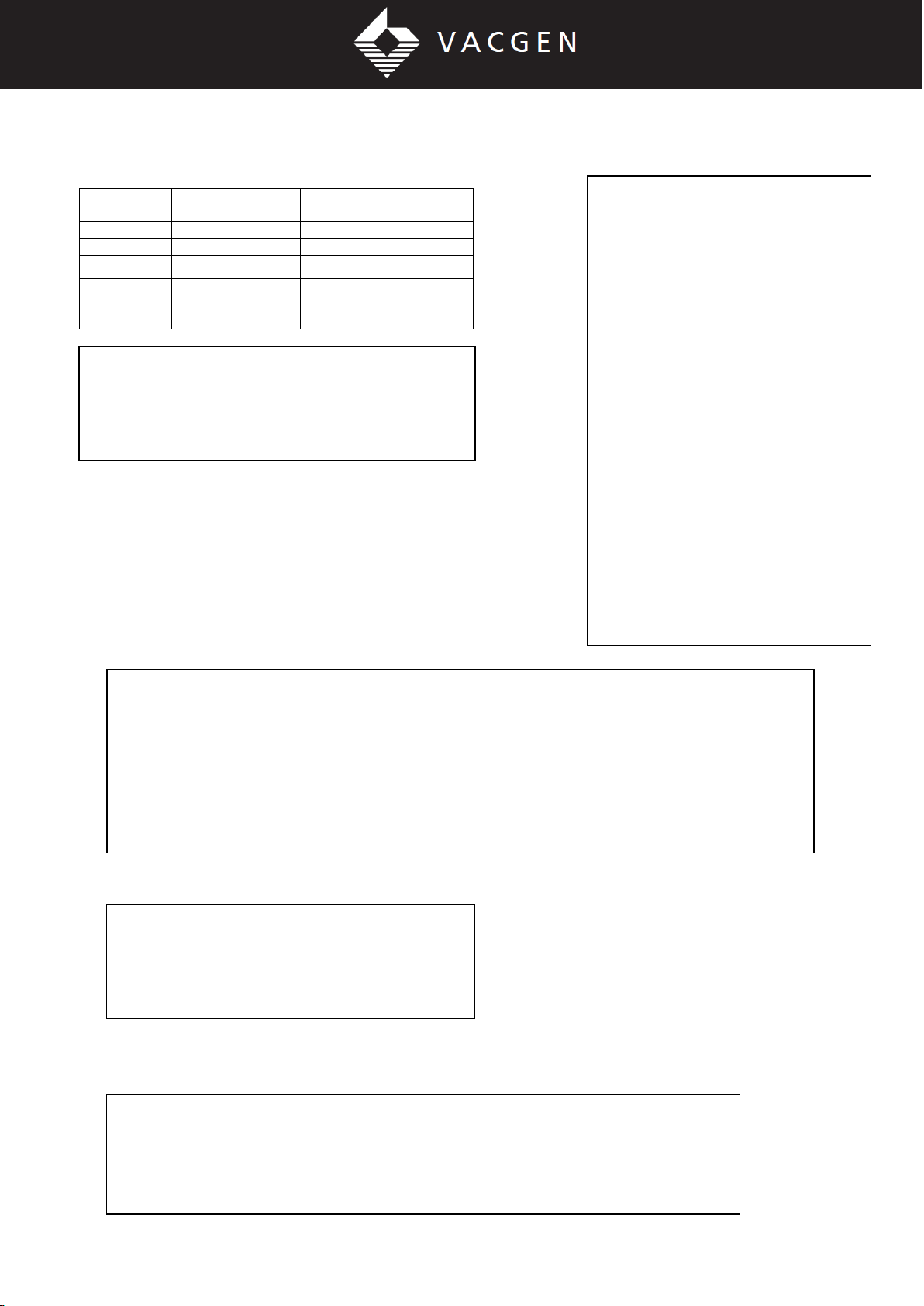
c. Bolt to the system flange using the correct size bolts and gaskets as indicated in the table below.
For tapped flanges use a thread lubricant, such as VACGEN ZTL on the bolt threads. Use washers
under bolt heads or nuts.

Page 8 of 35
[email protected] www.vacgen.com +44 (0) 1424 856 333
Flange details
Flange Size: NW63CF NW100CF NW150CF NW200CF
(4.5” OD) (6” OD) (8” OD) (10” OD)
Gasket size (VG reel): ZCU64 ZCU100 ZCU150 ZCU200
Tapped holes: M8 M8 M8 M8
Clearance holes (mm): O8.4 O8.4 O8.4 O8.4
d. Install equipment to the top flange, using the same guidelines as the base flange.
e. Fit and adjust the micrometers or motors as described in the sections below. When installing use
only the lifting handles. These are found at the base and top of all manipulators and should remain
attached until the translator is correctly mounted.
f. Before operation, remove the lifting handles and the shipping pin.
2.3 XY MICROMETER INSTALLATION
Caution: Note the vectorial limits of travel as given in the 'XY Motion' section of the introduction.
Exceeding these limits can permanently damage the bellows. There are NO stops fitted to restrict
vectorial movement.
a. Some micrometers are supplied with the barrels intentionally loose in the housing. With the
shipping pin in position, adjust the micrometers to read the central position of the stage. The
graduated thimble can be rotated to 'zero' the scale. Tighten the clamp and remove the shipping pin
for use.
Warning: It is the responsibility of the user to fit emergency stops to automated equipment. (Note:
VACGEN stepper motor controllers have a facility for adding emergency stops.)
2.4 XY MOTOR INSTALLATION
a. Motor wiring details are given in Appendix B.
b. Bolt the stainless steel block and lead screw assembly to the slide.
c. Screw the anti-backlash assembly onto the lead screw.
d. Carefully fit the main mounting block over this assembly. Secure the anti-backlash assembly by
tightening the single lead screw, located under the plate, against the central spacer. It may be
necessary to unscrew the anti-backlash assembly to achieve this.
c. Rotate the anti-backlash assembly so that the mounting block is within 1mm of the side of the XY
Table. (Tip: The pulley can be turned around and used as a convenient handwheel.)
f. Remove the shipping pin and loosen the stainless steel block holding the lead screw.
g. Bolt the mounting block to the side of the Table using 3 x M6 bolts.

Page 9 of 35
[email protected] www.vacgen.com +44 (0) 1424 856 333
Figure 2 - Motor on T108, T208 and T211 tables
2.5 XY MOTOR LIMIT SWITCHES
a. Remove the shipping pin and switch off any power to the motors.
b. Use the manual knob to move either motor from the central position to either limit of travel.
c. Loosen the limit protection microswitch and adjust its position until the switch can be heard to
operate (click) at the limit position. Repeat for the other limit of travel.
d. Return the first motor to the central position before attempting to set the second pair of
microswitches.
Caution: Microswitches do not protect against vectorial limits unless they are set to the 45ovector, i.e.
X=Y=5.5mm for =612.5mm stages, or X=Y=17.6mm for +25.0 stages. It is important that both
microswitches are correctly adjusted so that there is no risk of driving into the end stops as this may
damage the support tube, XY bellows or drive mechanism.
Caution: Microswitches are intended for emergency use only. Do not use microswitches as position
indicators or datum markers. Stepper motors may overrun by several steps when a microswitch is
activated, particularly if traveling at speed. Always check the datum position and reset as necessary.
2.6 Z MOTOR INSTALLATION
Note: Changing the side to which the motor is fitted is possible, but will cause the direction of motion
to reverse. It is therefore necessary to reverse the microswitches.

Page 10 of 35
[email protected] www.vacgen.com +44 (0) 1424 856 333
a. The motor is assembled with a housing and the sprung part of an Oldham coupling. This assembly
is fitted over the locator which is permanently mounted to the Z slide of the Omniax.
b. As the motor is being fitted, rotate the motor shaft by hand to engage the coupling. Once
positioned, tightened the thumbscrew into the groove on the locator to secure the motor.
Figure 3 - Z Motor arrangements
2.7 Z MOTOR LIMIT SWITCHES
Caution: It is important that both microswitches are correctly adjusted so that there is no risk of
driving the knee into the end stops as this may damage the drive mechanism or lead screw.
Caution: Microswitches are intended for emergency use only. Do not use microswitches as position
indicators or datum markers. Stepper motors may overrun by several steps when a microswitch is
activated, particularly if traveling at speed. Always check the datum position and reset as necessary.
The microswitches are located inside the cover extrusion and are removed for bakeout with the
extrusion. Move the knee away from the switches by at least 25mm before removal or replacement of
this cover. The microswitches should be factory set. Check by slowly driving the Z-slide to either end
of travel until the switch operates, preventing further movement in that direction. To reset the
microswitches;
a. Position the knee at the limit position required.
b. Loosen the two screws holding the microswitch mounting bracket to the cover extrusion and slide
the bracket to a position where the microswitch makes contact.
c. Re-tighten the two screws and check, by slowly running the knee onto the switch, that contact is
being made consistently.

Page 11 of 35
[email protected] www.vacgen.com +44 (0) 1424 856 333
Figure 4 - Z slide Microswitch layout (schematic)
3. OPERATION
3.1 NORMAL USE
3.1.1 Important information
Warning: Do not use this equipment with positive internal pressure above the specified maximum.
Warning: Keep clear of moving parts.
Caution: Do not operate unless the shipping pin is removed (see figure 1).
Caution: The Omniax uses precision guidance mechanisms: avoid undue strain due to clashes with
fixed objects, exceeding the vectorial limit, overloading the top flange, leaning on the equipment, etc.
Caution: Where motors are fitted, the motor connector must not be disconnected unless the power to
the drive has first been switched off. Allow a few seconds for the circuits to discharge.
Caution: Microswitches are intended for emergency use only. Do not use microswitches as position
indicators or datum markers. Stepper motors may overrun by several steps when a microswitch is
activated, particularly if traveling at speed. Always check the datum position and reset as necessary.
3.1.2 Operation
• The unit must be correctly installed, and the information above followed carefully.
• Manual operation is straightforward and needs no special consideration.

Page 12 of 35
[email protected] www.vacgen.com +44 (0) 1424 856 333
• Operation with the stepper motor is dependant on the motor controller used, and the user should
refer to the controller instructions.
• If any movement becomes tight, or if backlash (play) becomes visible, the unit will require
maintenance.
• Routine maintenance is required. See section 4.1
3.2 BAKEOUT
3.2.1 Bakeout guidelines
Warning: Harmful gases may be evolved if this product is heated above the maximum specified
bakeout temperature.
• Heater tape should not be used over the bellows and should be avoided on all manipulation
equipment as it can cause local hot spots.
• The temperature sensing element controlling the heaters must be suspended in air near the
translator and at a level approximately 50 -100 mm below the highest part of the translator.
• In no event should the temperature sensing element be in contact with or attached to any part of the
translator or the vacuum system, i.e. it must always sense the air temperature.
• Centralize the XY stage and, on horizontally mounted translators, position the Z slide at mid-travel.
• Remove all microswitches and motors as described below..
• Remove all non-bakeable equipment from the bakeout zone.
3.2.2 Removing motors for bakeout
a. Switch off the controller before disconnecting any motor.
b. For the XY motors, remove the three screws securing the motor mounting plate and remove the
motor, microswitches, drive belt and all cabling from the bakeout zone.
c. For the Z motor, first move the knee away from the limit positions by a minimum of 25mm. Unplug
the connector between the motor and microswitch cover. Loosen the single thumb screw on the motor
housing and remove the motor. Remove the cover extrusion that encloses the microswitches by
unscrewing the two screws securing it to the side of the Z-slide. Remove all cabling from the bakeout
zone.

Page 13 of 35
[email protected] www.vacgen.com +44 (0) 1424 856 333
4. MAINTENANCE
4.1 ROUTINE MAINTENANCE
4.1.1 Inspection schedule
The following inspections and procedures should be performed after 150 to 200 hours of accumulated
bakeout or when the Z-slide has traveled 150m.
4.1.2 Screw fixings
Check that all screws are secure: not slack nor excessively tight. It will be noted during any
dismantling that Belville washers (disc springs) have been fitted under certain screw heads. It is
important that these washers are refitted in the correct locations.
4.1.3 Gravity compensation springs
(Horizontally mounted units only):
Warning: The spring compensators are pre loaded and have sharp edges do not attempt to
dismantle.
a. Visually inspect the springs to cheek that no spring leaves have broken. Any broken springs must
be replaced as soon as possible. Contact VACGEN Service Department for information.
b. Check that the springs correctly support the payload by operating the vertical (Y) micrometer (or
manually operate the Y motor). It will be possible to find a position where the resistance to raising the
stage is the same as the resistance to lowering it. This is the neutral position.
c. Check that the neutral position is within 5mm of the central position. If the neutral position is
beyond this limit, the compensator is not balanced, and action is required to correct it. Contact
VACGEN Service Department for information.
4.1.4 XY Micrometer or motor stiffness
a. Compare the action of the X and Y drives by hand operation at the neutral position (see above to
establish the neutral position). Both movements should feel smooth and have the same degree of
stiffness. If a movement is believed to be stiffer than normal, proceed as follows:
b. At the neutral position, loosen (but do not remove) the screw(s) that secure the micrometer or
motor housing to the XY table. Repeat the check for stiffness.
c. If the drive is now significantly smoother or less stiff than previously, the slides may have loosened
or the drive may be misaligned with the XY table.
d. Check for loosened slides.
e. Check for misalignment by observing the gap between the micrometer (or motor) and the housing
when the bolts are just loosened. An uneven gap indicates misalignment. This can be rectified by
fitting shims: e.g..
a thin sheet or foil between the housings at the correct position to eliminate misalignment.
f. If the drive remains stiff, this may be due to incorrect lubrication, wear of the drive, or damage.
4.1.5 Monitoring the Two-Part Nut on the Z slide
The two-part nut helps prevent collapse of the Z-slide into the chamber in cases of extreme thread
wear. The diagram below shows the arrangement.
Warning: It is essential for safety reasons that regular checks are made.
• The rate of wear depends on many factors such as lubrication, usage, applied load and orientation.
• When failure of the main nut occurs the gap between the two nuts (shown as 'h' in the figure) will
become zero as the full load is taken on the follower nut. Warning: The slide must not be used in this
condition; if usage continues, a dangerous collapse is possible.

Page 14 of 35
[email protected] www.vacgen.com +44 (0) 1424 856 333
• The condition of the nut must be monitored to ensure
that wear of the main nut is never such that the follower
nut is needed to support the load.
• The state of wear of the main nut can be checked by
monitoring the following three conditions:
a. The gap distance, h: If the gap reduces by 0.5mm from
that measured when first installed, the nut should be
replaced.
b. The torque required to turn the worm gear shaft: If the
torque required reaches a level of 40Ncm (60 oz.in), the
nut should be replaced.
c. The free play of the follower nut on the pin connecting
it to the main nut: If the follower nut has no free play on
the pin, the nut should be replaced.
4.1.6 Lubrication
Warning: Lubricants used in this product may cause irritation to sensitive skin. Wear protective
clothing.
Note that Carbaflo grease discolours with time, particularly where regular bakeouts are applied to the
equipment. This is normal and does not affect the behavior of the lubricant.
a. Z slide lead screw, linear guide shafts, worm and wheel gears:
Clean dirty and excess grease off the components. Lubricate with Carbaflo grease, ensuring that all
contact surfaces are covered by a film of grease. Should the slide develop a dry squeak, lubricate
immediately.
Warning: Keep clear of moving parts.
b. Z slide hall bearings (drive screw and worm drive shaft):
Use a small quantity of Carbaflo fluid to lubricate each bearing. Apply using a dropper or by dipping a
clean wire into the container and allowing it to drip onto each bearing.
c. Z slide Oldham coupling (motorised Z slide only):
Clean dirty and excess grease off the coupling. Lubricate with Carbaflo grease.
d. XY Micrometers:
Move one micrometer at a time to the limit position so that the spindle is fully retracted. Unscrew and
remove the small knurled knob that retains the micrometer thimble. Pull the thimble away carefully.
Apply Carbaflo grease to the lead screw. Replace the thimble and knob.
e. XY stage motor lead screw:
Drive the motor to either limit of travel, periodically stopping to lubricate the lead screw as it becomes
visible on either side of the anti-backlash assembly.
Warning: Keep clear of moving parts.
f. XY Slides:
Use a small quantity of Carbaflo fluid to lubricate the slide. Apply using a dropper or by dipping a wire
into the container and allowing it to drip onto the exposed slide. Note that it is not possible to lubricate
the full length of the slide, but by cycling the movement a few times, the lubricant will be adequately
dispersed.

Page 15 of 35
[email protected] www.vacgen.com +44 (0) 1424 856 333
g. Fixing screws:
All fixing screws should be treated with high temperature thread lubricant.
4.1.7 Adjustment of the XY slides
a. If play develops in the XY slides, three adjustment screws are provided on each axis. The X slide
adjustment screws are located below the Y axis micrometer (or motor). The Y adjustment screws are
on the side of the top plate, on the same side as the shipping pin.
b. Before adjusting these three screws, it is first necessary to loosen the screws which retain the
bearing closest to the adjustment screws.
c. Check that the roller cage between the slides is centrally positioned along the length of the slide.
d. Tighten the middle adjustment screw first, to finger tight only. Then tighten the outer adjustment
screws, to finger tight.
e. Finally, tighten the bearing retaining screws.
4.2 CORRECTIVE MAINTENANCE
4.2.1 Guidelines for dismantling and re-assembly
a. Centralize the XY stage and retract the Z slide, but leave the knee at least 25mm away from the
limit positions.
b. Disconnect all power and instrumentation and remove the OMNIAX from the vacuum chamber.
c. Bolt the Omniax to a suitable stand that allows it to be worked on securely in the vertical position
(such as the transit stand supplied with the translator).
d. Note the orientation of parts as they are dismantled: i.e., disk (or Bellville) spring washers under
screw heads, the orientation of bearings and tubes.
c. When reassembling always fit new copper gaskets.
f. Apply thread lubricant to all fixings which are not in-vacuum but do not allow contamination of the
vacuum with thread lubricant.
g. Replace parts in their original orientation.
4.2.2 Removal of the central assembly
(i.e.: support tube + sample holder + Z bellows +
rotary drive or other equipment fitted above the
knee).
a. All sample handling equipment must either be
removed from the bottom of the manipulator, or be
able to pass through the support tube bearing: i.e..,
through a bore equivalent to the outer diameter of
the support tube. It will be necessary to remove the
radial screws which retain the rotary
drive bearing housing.
b. Remove the Z drive hand wheel or motor.
Loosen the grub screw holding the knurled nut on the
Z
drive worm shaft (see diagram below). Unscrew this
nut by about two turns relative to the spacer
which has a radial hole. This will
introduce end play to the shaft

Page 16 of 35
[email protected] www.vacgen.com +44 (0) 1424 856 333
assembly. Remove the circlip from the side shown in the diagram and remove the shaft.
c. . Unscrew and remove the eight 13 mm AIF nuts which hold the lower flange of the Z bellows to the
XY module.
d. Unscrew and remove the two hinge pins which retain the upper bellows flange to the knee.
Carefully lift the assembly away.
Note: some Omniax translators (normally long travel versions fitted with the 32mm diameter support
tube) have a hidden pin that prevents the top flange rotating. In this case, pull the top flange away
from the knee before lifting the assembly away. It may be necessary to prise the knee forward by
carefully using a screwdriver as a lever tool.
e. Replacement is a reversal of the above procedure but note that the end play must be taken out of
the Z drive worm gear shaft by tightening the knurled nut against the circlip (it will help to press firmly
against either end of the shaft to seat the circlip).
4.2.3 Z-slide removal
a. First remove the central assembly.
b. Unscrew and remove the eight M6 bolts that secure the base of
the Z slide casting to the top plate of the XY stage, and lift this
assembly away.
4.2.4 Z bellows removal
a. First remove the central assembly.
b. Remove the sample handling equipment from the bottom of
the manipulator, including all instrumentation services. Details will
vary depending on the configuration. The following text assumes a
VACGEN rotary drive is used.
c. Check the condition of the rotary drive shaft that protrudes
from the bearing
housing. Carefully clean off any burrs or high spots that might
prevent the
shaft from being drawn through the bearing housing. Wet the
surface of the protruding rotary drive shaft with alcohol and
withdraw the rotary drive. Be careful to avoid straining the rotary
drive shaft which is now unsupported.
d. Remove the eight MS cap head bolts holding the feedthrough
chamber or other such device to the hinged flange.
c. Looking inside the hinged flange, loosen the M4 grub screws
that are exposed (but do not remove).
f. Remove the spiral retaining ring by prising out at the start point and working out of the groove and
remove the support tube through the hinged flange.

Page 17 of 35
[email protected] www.vacgen.com +44 (0) 1424 856 333
g. All bellows are fragile and expensive to replace. Please handle with care.
h. When refitting the support tube to the hinged flange, tightening the grub screws around the flange
by a small amount in turn to avoid jamming.
4.2.5 XY bellows removal
a. First remove the central assembly and Z-slide.
b. Note carefully the orientation of the support tube bearing: a single small hole identifies the fixed
side of the bearing (see diagram below). Remove the four M4 screws which retain the bearing and
remove the bearing assembly from the XY stage.
c. Remove the six M6 hexagon head bolts around the top flange of the XY stage. Note that these are
not equispaced.
d. Remove the ring of twelve M6 hexagon head bolts that hold the flared tube to the underside of the
XY table. The XY bellows can now be removed.
c. All bellows are fragile and expensive to replace. Please handle with care.
4.2.6 Support tube bearing removal
a. Refer to XY bellows removal above, but when reinstalling, ensure that bearing is orientated
correctly: Horizontally mounted translators must have the fixed side of the bearing down most.
Vertically mounted units which are subject to transfer forces should have the fixed side opposite to the
main transfer device.
4.2.7 Spares and Accessories
Lubrication kit LUBEK, including; VG Thread Lubricant, Carbaflo grease, solvent for Carbaflo and
gloves.
Tool kit TOOLK, including; Metric spanners, hexagon keys, circlip pliers
and gloves
Electrical and VACGENcouple instrumentation: EFT series feedthroughs:
Contact VACGEN for available feedthroughs and for information on instrumentation options.
Rotary Drives: RD series (RD I, RD2 and RD224) precision rotary drives. These are compatible with
the Omniax.

Page 18 of 35
[email protected] www.vacgen.com +44 (0) 1424 856 333
Sample Holders and Sample Mounts: SH series: An extensive range of compact sample handling
options is available, many in low magnetic materials as standard. These include secondary rotation
sample mounts (or sample holders); Sample heaters for resistive or electron beam heating,
HST and EBH series; Sample cooling accessories, LN and LNRX, integrated sample transfer
system, the XL25 series, and others. Sample Accessories: VACGEN can provide individual items of
sample hardware, such as UHV compatible wiring, molybdenum screws, ceramic isolators and so on.
Please state your requirements clearly.
Motors: Manual Omniax actuators can be upgraded to stepper motor options. Most rotary actuators
can also be upgraded. Incremental encoders versions are also available. Please state your
requirements clearly.
Motor controllers: The SDU, SMC and SMC-E series of powerful, bipolar motor controllers can be
used to operate any VACGEN motor, or any other 4 phase hybrid stepper motor.
Z-slide nut replacement: MXNUTK. Service kit for replacing the lead screw nut in cases of extreme
wear.
Associated Equipment: Details of rotary drives, specimen manipulators, heating, cooling and other
accessories are covered by separate instructions. If in any doubt regarding compatibility or fitting
procedure, contact VACGEN for assistance
4.2.8 Factory Servicing
A factory servicing scheme exists for all translators. The translator should be returned to the VACGEN
factory with a covering order. Please note also the terms and conditions for returning goods, outlined
in the 'Repair' section in the front of this manual that apply to good returned for servicing. The
servicing scheme includes a complete strip down, cleaning, re-lubrication and re-assembly.
When shipping the unit use the original packing and pack with care to avoid expensive transit
damage. Consider that the crate is liable to be dropped on any face or corner.

Page 19 of 35
[email protected] www.vacgen.com +44 (0) 1424 856 333
APPENDIX A. HORIZONTAL MOUNTING
Al. INTRODUCTION
The purpose of correct horizontal mounting compensation is to relieve the Y-axis micrometer of
excessive load and to reduce stresses on the chamber and components of the translator. Suitable
compensation must be used on all OMMAX units.
Three options are available:
* Option A is mainly used where the 'Z' travel is 600 mm or less.
* Option B is required to support units with Z travels greater than 600mm or where heavy equipment
is transported on the 'Z' carriage.
* Option C is used for fixed XY stages (or "Z-only" adaptors), and is
not dependent on extent of Z travel.
In all cases the position and setting arrangement instructions must be followed to ensure that the
equipment will work satisfactorily over its full life.
A2. OPTION A: STANDARD COMPENSATOR USA
Description
The HSA compensator comprises a floor mounted sprung lever mechanism, a tube clamp attached to
the translator and a connecting push-rod. Constant tension springs on one side of the lever provided
an upward force on the opposite side.
Since there are two positions of both the spring drums and push rod mount, four multiplying ratios are
possible. Also, the number of spring leaves can be varied and so the upward force can be closely
matched to the weight of a particular device.
The position at which the compensator acts against the translator can be adjusted by varying the tube
clamp position. This should be set at the centre of gravity when the Z-slide is in mid-position.
Spring Parameters
Warning: These springs are very powerful and have sharp edges. GREAT CARE should be taken to
avoid physical injury if any attempt is made to disconnect the springs. First remove the translator from

Page 20 of 35
[email protected] www.vacgen.com +44 (0) 1424 856 333
the system. ALWAYS wear tough gloves and remove the spring from the axle rather than the outer
end.
These values relate to OMNIAX translators that include XY stage, rotary drive, feedthrough chamber
with feedthroughs and normal specimen holders. The Z slide is taken as motorised but the XY stage
is manual. For other configurations, such as the CTPO or cryostats, please consult VACGEN.
Z Travel Clamp position, X Spring Push rod mount Total number of
(mm) (mm) Position position spring leaves
100 0 Outer Outer 6
200 0 Inner Inner 7
300 0 Inner Inner 7
400 50 Outer Outer 7
500 90 Outer Inner 6
600 130 Outer Outer 8
Important: The system flange will need to carry approximately 25% of the weight of the OMNIAX.
Ensure that the system construction is stable is designed to support at least 50% of the full OMNIAX
weight. The HSA stand will relieve the majority of the cantilevered weight of the unit.
Normally the OMNIAX will be matched with its compensating stand, and so there will be no need to
alter any of the parameters outlined in the table above.
It will be necessary first to ensure that the push rod is of the correct length:
a. Establish the correct length, H, of the push rod tube from the measured value, L. (H = L-524). The
push rod end fittings should be adjusted to their mid position when making this calculation.
b. Pull one of the end fittings from the push rod tube and cut the tube back by the required amount.
c. Replace the end fitting.
When ready to install, offer the OMNIAX to the chamber and, WHILST SUPPORTING THE END
CAREFULLY ON JACKS, bolt to the chamber. Continue to support the device whilst the compensator
stand, is maneuvered into position and the push rod is fitted between the two countersunk pivot
points. The jacks may now be carefully removed checking the following
* With the X, Y and Z motions at mid travel check that the Y micrometer is as free to move as the X
micrometer. If any undue stiffness is noticed or if there is more resistance in one direction than the
other, then advice should be sought from VACGEN.
* With the XY stage centralized check that the lever arm is horizontal and the push rod vertical.
Adjustment may be made via the end fitting. Also check that full Y travel can be achieved without
contact being made with the lever arm stops.
* The base of the stand must be firmly bolted in position.
* IMPORTANT: Protect the OMMAX and the compensation unit from accidental knocks that could
dislodge the spring loaded push rod and over-stress the system flange.
A3. OPTION B: TRAVELLING COMPENSATOR HSB
Description
This compensation device consists of three separate units using constant tension springs in each
case.
* A traveling unit that moves along a track and supports the combined moving weight of the knee,
feedthroughs, rotary drive etc.
* An outboard unit at the extreme outer end of the Z slide that reduces the cantilevered moment
resulting from the extended mass.
This manual suits for next models
1
Table of contents