VacPak-It 186VMC16F User manual

Service Manual
This manual is for a certified service technician and should not be used by those who are not properly trained.
This manual cannot cover all possible conditions that may occur and is not intended to be all encompassing.
You should read this manual in its entirety and the specific repair you wish to do prior to starting the repair.
This will allow you to determine if you have the correct tools, instruments, and skills to perform the procedure.
REVISED: 07/2021
NOTICE
#186VMC16F
(2) 16" Seal Bars
Floor Model Chamber
Vacuum Sealer
#186VMC20F
(2) 20" Seal Bars
#186VMC20FGF
(2) 20" Seal Bars with Gas Flush
NOTICE
This manual is for a certified service technician and should not be used by those who are not porperly trained. This
manual cannot cover all possible conditions that may occur and is not intended to be all encompassing. You should
read this manual in its entirety and the specific repair you wish to do prior to starting the repair. This will allow you to
determine if you have the correct tools, instruments, and skills to perform the procedure.
REVISED: 1/2022

2
Table of Contents
Initial Setup ................................................................................4
Adjusting Cycle Times...............................................................5
Operation ...................................................................................6
Troubleshooting.........................................................................8
Part Replacement .................................................................... 10
Pre-Maintenance ..................................................................... 10
Fuse .......................................................................................... 10
Lid Parts.....................................................................................11
Sealing Bar............................................................................... 12
Lid Latch Assembly.................................................................. 12
Pressure Gauge ....................................................................... 13
Front Circuit Board.................................................................. 13
Piston........................................................................................ 14
Power Switch ........................................................................... 15
Vacuum Pump.......................................................................... 15
Lid Strut .................................................................................... 16
Lid Microswitch........................................................................ 17
Transformer.............................................................................. 18
Main Circuit Board................................................................... 18
Small Solenoid Valve............................................................... 19
Small Control Solenoid Valve .................................................20
Large Control Solenoid Valve .................................................20
Drain and Inlet Solenoid Valve ............................................... 21
Wire Diagram for VMC16F......................................................22
Wire Diagram for VMC20F .....................................................23
Wire Diagram for VMC20FGF ................................................24

3
Specifications
186VMC16F 186VMC20F 186VMC20FGF
Overall Height 40" 40" 40"
Overall Depth 21-1/7" 25-2/3" 25-2/3"
Overall Width 10-1/6" 23-5/8" 23-5/8"
Chamber Width 16-3/4" 20-3/4" 20-3/4"
Chamber Depth 17-1/4" 21-1/4" 21-1/4"
Chamber Height 7" 7" 7"
Seal Bar Length
(Quantity) 16" (2) 20" (2) 20" (2)
Voltage / Wattage 110V / 1180W 110V / 1180W 110V / 1180W
For Warranty Inquiries or Service:
This warranty is only valid on equipment purchased from an authorized dealer. To make a claim
please contact Ready Kitchen Warranty
Phone : 717-381-4844
Please have your model number, serial number, proof of purchase, and proof
of qualified installation ready before calling
Email : help@readykitchenwarranty.com
Please include your name, model number, serial number, proof of purchase,
proof of installation, and a brief description of the issue. Including clear
pictures of the issue will help expedite the process. Failure to include one or
more of these items will extend the processing time
Serial Plates
Ready Kitchen Warranty
Note: All units are labeled with model numbers, Voltage,
Wattage, Serial Number, Item number, and Certifications
on the rear of the unit
Please do not remove this label
(序列号按订单数量排序,下一单流水号接着上一单流下去)
(注意:下一单流水号接着上一单流下去)
MC13f1002107000191 ...… MC13f1002107000240
M为真空机
C13f 为产品型号
100 为100客户
000191...000240 为流水号
2107 为年月
Serial #:
条形码: Code 128 码生成
序列号编排规则:M+产品型号+客户编码(3位)+订单时间年月(4位)+流水号(6位)
Made in China
70x65mm
CAUTION:
DO NOT IMMERSE IN WATER.
To provide continued protection against risk of
electric shock, connect to properly grounded outlets only.
ATTENTION:
NE PAS IMMERGER.
Pour assurer une protection continue contre les risques
de choc électrique, branchez à une prise correctement
mise à la terre.
Item: 186VMC10OP
Voltage: 110-120Vac 60Hz
Power: 1000W
4003219
CONFORMS TO
UL STD. 963
CERTIFIED TO CSA
STD. C22.2 NO.68
Serial #:

4
Initial Setup
1. Dispose of packaging properly
2. Open the lid and leave it open
3. Remove items from inside the vacuum cham-
ber, filler plates, sealing bars, electrical plug, oil
for pump, and oil filler container
4. Install sealing bars onto heating posts
(Fig. 1 - A)
5. Remove oil fill window from the side of the ma-
chine by removing 4 Phillips screws (Fig. 2 - A)
6. Remove oil port cap with an 8mm hex key
(Fig. 2 - B)
7. Use oil filler container to fill pump via oil port,
fill pump up to half way between minimum and
maximum lines. (Fig. 2 - C)
Note: Oil level will fluctuate during initial
filling, ensure level holds before moving on
8. Replace oil port cap and oil fill window
9. Attach the supplied power cord to the rear of
the machine (Fig. 3)
Fig. 1
A
BA
AA
A
C
Fig. 3
Fig. 2
A
Note: All units are shipped without oil in the pump, DO NOT operate without putting
required oil in the pump as it will damage the pump and void the warranty

5
Note: All adjustments must be made with the lid open
1. Turn the power knob to the "ON" position
2. Press the "SET" button on the front control panel to enter the setup mode and move through
the dierent cycles (Fig. 4 - A)
3. Each cycle light will light a solid blue color and show the current duration of the cycle in
seconds
4. Use the "UP" or "DOWN" arrow buttons to adjust as needed (Fig. 4 - B)
Note: Vacuum Cycle is adjustable from 0 - 90 seconds (5 second intervals)
Gas Cycle is adjustable from 0 - 10 seconds (0.5 second intervals)
Sealing Cycle is adjustable from 0 - 6 seconds (0.5 second intervals)
Cooling Cycle is adjustable from 0 - 10 seconds (0.5 second intervals)
5. After setting all the cycle times, press the "SET" button again to exit the setup mode
(Fig. 4 - A)
6. Ensure no cycle lights are on as machine will not operate if any cycle lights are on
Fig. 4
A
B
Adjusting Cycle Times

6
Operation
Note: Ensure pump oil level is correct before using
machine
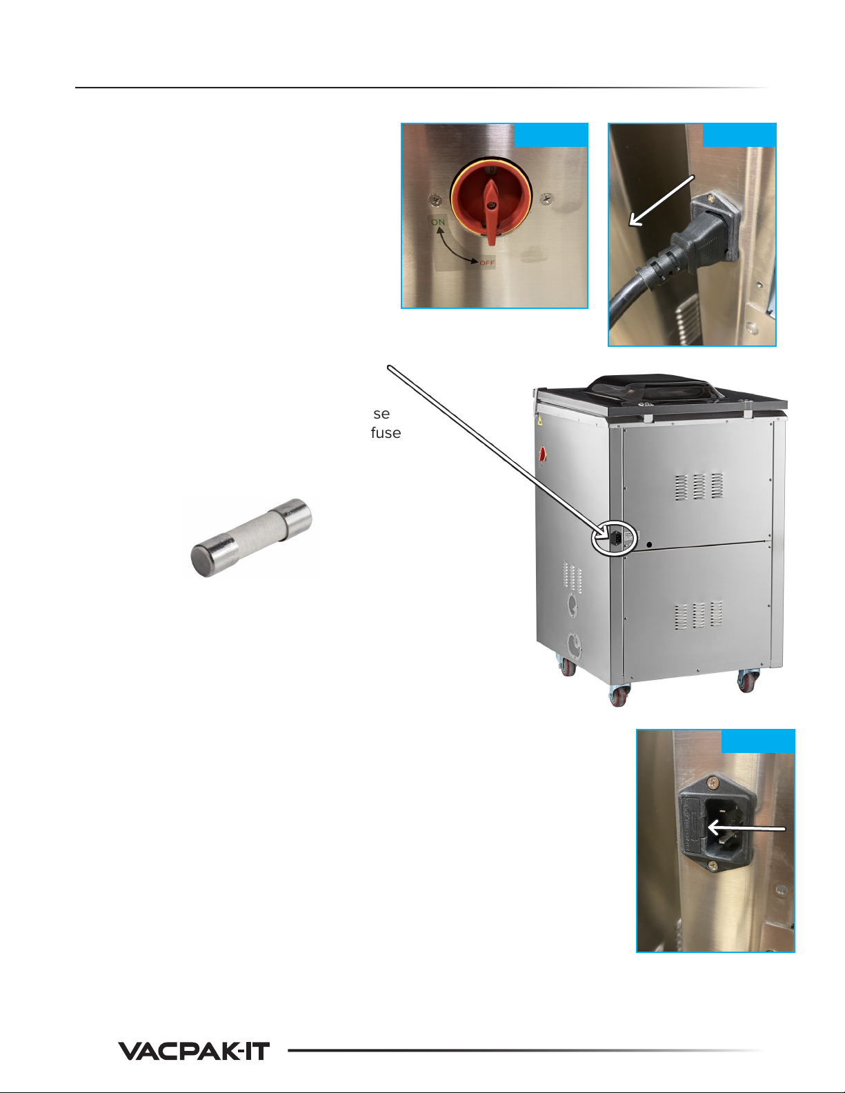
1. Plug power cord into adequate power supply
2. Ensure lid lock is disengaged and lid is open
Do Not use lid lock during operation. Lid lock
is ONLY for storage of machine
3. Turn machine on via side power knob
Note: Once unit is on, closing the lid will start
the vacuum/sealing process. If
accidentally started, press the "STOP"
button immediately, located on front
control panel (Fig. 5)
4. The front control board will now show "ON" (Fig. 6)
5. Chose the correct vacuum chamber pouch for this machine
and your product
Note: 186VMC16F can handle up to a 16" x 16" pouch
186VMC20F and 186VMC20FGF can handle up to a
20" x 20" pouch
6. Once your product is placed into the pouch, ensure there is at
least a 2" gap between the product and the pouch opening
Note: Remember to protect sharp items from puncturing
the pouch
7. Lay the pouch flat in the vacuum chamber and lay the opening
flat across the sealing bar. Ensure there are no wrinkles in the
pouch across the sealing bar and that the pouch end is not out-
side the chamber
7a. If you have a gas flush option, ensure one of the gas ports is
sticking inside the pouch (Fig. 7)
Gas pressure regulator set between 5 and 12 psi
8. Close the lid, press and hold down the corners of the lid until
the vacuum process begins, typically 3 - 4 seconds
Fig. 5
Fig. 6
Fig. 7
9. The VacPak-It unit will now go through its process based on the settings that were adjusted
(Vacuum, Gas, Sealing, Cooling)
10. Once the cycle is completed, the lid will release and open
11. Enjoy your freshly vacuum packed food
Sealing bar

7
Preventative Maintenance
Daily Cleaning:
1. Remove Sealing bars and wipe clean with a damp soft cloth only
2. Wipe the inside of the chamber, lid and filler plates with a damp soft cloth and a mild soap to
remove any food or any other debris. Recommended mild soap part # 999SUNBRIGHT
3. Wipe the outside of the machine as needed with appropriate stainless steel cleaner to remove
any food or debris. Recommended stainless steel cleaner part # 148EXCEL
4. Inspect power cord for any damage and replace if damaged
5. Ensure pump oil level is at required level using the pump site gauge. Recommended oil part
# 186OILSQT

8
Troubleshooting
PROBLEM POSSIBLE SOLUTION PAGE
Bags are not sealing
Adjust sealing time cycle 5
Ensure pouches are laying flat on sealing bars 6
Ensure sealing bars are clean 7
Ensure pouch has no wrinkles 6
Check sealing foam 11
Check solenoid valve 19
Check piston 14
Check circuit board 18
Unit is making an extra
loud noise when running
Check pump site gauge fluid level 4
Check lid sealing gasket 11
Check vacuum silicone tubes
Check pump 15
Bags are not being fully
vacuumed
Check pump site gauge fluid level 4
Adjust vacuum cycle time 5
Check lid 11
Check lid sealing gasket 11
Check voltage is getting to the pump 15
Check solenoid valve 19
Check main circuit board 18
Front circuit board does
not come on
Ensure correct power is supplied
Ensure unit is plugged in
Check to see if fuse is blown 10
Check switch for voltage and function 15
Check front circuit board 13
E01 error is showing
Ensure lid was held down to start 6
Check lid 11
Check lid sealing gasket 11
Check microswitch 17
Vacuum cycle does not
start
Ensure unit is plugged in and turned on
Ensure lid is closed 4
Adjust vacuum cycle time 5
Ensure cycle time setup has been exited 5
Check microswitch 17
Check main circuit board 18

9
Troubleshooting
PROBLEM POSSIBLE SOLUTION PAGE
Lid will not open or is
very slow to open
Ensure all cycles are complete
Adjust cycle times if necessary
Check solenoid valve 19
Check control solenoid valve 21
Check piston 14
Check silicone tubing
Check circuit board 18
Pump starts while lid is
still open
Check microswitch 17
Check circuit board 18
LP error is showing
Check fuse 10
Check power cord
Check transformer 18
CLO error is showing
Check silicone tubing for leaks
Check control solenoid valve 19
Check solenoid valve 20
Check circuit board 18

10
Part Replacement
Testing: Good fuse = continuity across fuse
Bad fuse = no continuity across fuse
25 Amps / 250 Volts
Time Estimate: Approximately 5 minutes
Part: #186PFUSE1
1. Follow pre-maintenance steps
2. Open fuse holder box by gently pushing a
flat screwdriver into the side opening (Fig. 10)
3. Remove fuse and replace as needed
Fuse
Fig. 9
Fig. 10
Fig. 8
Pre-Maintenance
1. Turn o the unit (Fig. 8)
2. Unplug power cord from power supply
3. Ensure lid is open

11
Lid: Visually inspect for cracks or damage
Time Estimate: Approximately 30 minutes
Part: #186PLID16F (186VMC16F ONLY)
#186PLID20F(186VMC20F ONLY)
#186PLID20FGF1 (186VMC20FGF ONLY)
1. Follow pre-maintenance steps from page 10
2. Remove 4 Phillips screws from each hinge plate at the
rear of the lid and hold the lid to ensure it does not fall
(Fig. 11)
Sealing Foam: Visually inspect for cuts or missing sec-
tions, replace if any are found
3. Remove sealing foam from lid by pulling it out of the
mount channel on the lid (Fig. 12)
Part: #186PSEALPAD2 (186VMC16F ONLY)
#186P20FTOPBA (186VMC20F & 186VMC20FGF)
4. Remove sealing foam mount channel by removing 1
Phillips head screw from the middle of the mount (Fig. 13)
Lid Sealing Gasket: Visually inspect cracks or damage,
replace if any are found
5. Remove lid sealing gasket by lifting it out of the
groove in the lid (Fig. 14)
Part: #186PGASKET4
6. Installation of new lid is reverse of removal steps
Lid parts
Fig. 11
Fig. 13
Part Replacement Continued
Fig. 12
Fig. 14

12
Part Replacement Continued
Testing: Visually look for marks and cuts to tape on
bar
Visually ensure bar is clean of debris
Continuity between post mount locations
(Fig. 12)
Replace: if marks and cuts are found on the
outside
if no continuity is found between
post mount locations (Fig. 12)
Time Estimate: Approximately 5 minutes
Part: #186PSEALBAR3 (186VMC16F ONLY)
#186P20FSB (186VMC20F ONLY)
#186P20FGFSB (186VMC20FGF ONLY)
1. Follow pre-maintenance steps from page 10
2. Lift sealing bar up from mounting tabs (Fig. 13)
3. Reverse steps to install
Sealing Bar
Fig. 13
Fig. 12
Time Estimate: Approximately 20 minutes
Part: #186PLID20
1. Follow pre-maintenance steps from page 10
2. Remove Phillips head screws from rear panel
Note: 11 screws on 186VMC16F, 8 screws on
186VMC20F and 186VMC20FGF
3. Remove mounting bolt and nut using a Phillips head
screw driver on the outside and a 6mm socket on the
inside
4. Installation is the reverse of the removal steps
Lid Latch Assembly

13
Part Replacement Continued
Time Estimate: Approximately 20 minutes
Part: #186PGAUGE2
1. Follow pre-maintenance steps from page 10
2. Remove 8 Phillips screws from Front Control
Panel and pull panel out of machine (Fig. 14)
3. Remove pressure hose from rear of Pressure
Gauge by pulling it straight o the barb fitting
(Fig. 15 - A)
4. Remove two hex nuts from mounting bar
with a 8mm socket (Fig. 15 - B)
5. Pull Pressure Gauge from mounting bar and
out the front of the Control Panel
6. Installation is reverse of the removal steps
Pressure Gauge
Time Estimate: Approximately 20 minutes
Testing: Good = Red wire in ribbon has voltage
Bad = Red wire in ribbon no voltage
Visual Test: Check board for black or burn
marks, scratches or cracks
Part: #186P20F17
1. Follow pre-maintenance steps from page 10
2. Remove 8 Phillips screws from Front Control
Panel and pull panel out of machine (Fig. 14)
Continued on Page 14
Front Circuit Board
Fig. 14
Fig. 15
A
BB
Fig. 16

14
Part Replacement Continued
3. Disconnect the wire ribbon that connects to the front
circuit board by pulling it straight out (Fig. 16)
4. Remove 3 Phillips head screws from the Front Circuit
Board (Fig. 17)
5. Installation is reverse of removal steps
Time Estimate: Approximately 20 minutes
Testing: Good = Continuity from screw post to
top post
Good = Visually inspect for no cracks
Bad = No continuity from screw post to
top post, replace
Bad = cracks found in housing, replace
Part: #186PPISTON
1. Follow pre-maintenance steps on page 10
2. Remove Phillips head screws from rear panel
Note: 11 screws on 186VMC16F, 8 screws
on 186VMC20F and 186VMC20FGF
3. Remove wire and ring terminal from stud post
on bottom of piston (Fig. 17)
4. Remove vacuum hose from side of piston
housing under vacuum chamber (Fig. 18)
5. Remove hex bolt from top of piston inside
vacuum chamber with a 13/16" socket (Fig. 19)
6. Cut sealing material from under side of vac-
uum chamber and push down on piston post,
inside vacuum chamber, to remove it (Fig. 20)
7. Installation is reverse of removal steps
Piston
Fig. 17
Fig. 17 Fig. 18
Fig. 19
Fig. 20
Screw post
Top post

15
Part Replacement Continued
Time Estimate: Approximately 20 minutes
Testing: Good = Continuity when switch is in "ON" posi-
tion or no continuity when switch is in "OFF" position
Bad = Continuity when switch is in "OFF" posi-
tion or no continuity when switch is in "ON" position
Part: #186PSWITCH
1. Follow pre-maintenance steps on page 10
2. Remove 2 Phillips head screws from front of power
switch on right side of machine (Fig. 21)
3. Remove 4 wires from back of power switch with a
Phillips head screw driver, noting wire location (Fig. 22)
4. Remove 4 Phillips head screws from mounting
bracket and remove power switch (Fig. 23)
5. Installation is reverse of removal steps
Power Switch
Fig. 21
Fig. 22
Fig. 23
Time Estimate: Approximately 60 minutes
Testing: Check power is getting to pump
Oil is milky white color, replace oil and check for
leaking vacuum hoses or excess moisture
in vacuum chamber or product
Replace if pump not creating vacuum
Part: #186PPUMP2
1. Follow pre-maintenance steps on page 10
2. Remove Phillips head screws from rear panel of unit
Note: 11 screws on 186VMC16F, 8 screws on
186VMC20F and 186VMC20FGF
3. Remove 4 socket head cap screws from vacuum pump
connector hose with a 4mm hex key (Fig. 23)
Note: Do NOT lose washer/gasket
Continued on Page 16
Vacuum Pump
Fig. 23

16
Part Replacement Continued
Time Estimate: Approximately 30 minutes
Part: #186PSTRUT2 (186VMC16F only)
#186PSTRUT3 (186VMC20F and
186VMC20FGF)
1. Follow pre-maintenance steps on page 10
2. Remove Phillips head screws from rear panel
Note: 11 screws on 186VMC16F, 8 screws
on 186VMC20F and 186VMC20FGF
3. Remove hex nut from lower Lid Strut mount-
ing tab with a 7mm socket (Fig. 26)
4. Remove Lid Strut from lower mounting post
by pulling away from mount arm
Continued on page 17
Lid Strut
4. Remove 3 hex nuts with a 14mm socket from under the
machine for the mounting post legs for the pump (Fig. 24)
5. Disconnect the power wires going to the Main Circuit
board (Fig. 25 - B)
6. Remove Phillips head screw that is securing the
ground wire terminal (Fig. 25 - A)
7. Remove wiring and pump from inside machine
8. Installation is reverse of removal steps
Fig. 24
Fig. 25
A
B
Fig. 26

17
Part Replacement Continued
5. Remove Phillips head screw from upper Lid
Strut mounting tab (Fig. 27)
6. Remove Lid Strut from upper mounting post
(Fig. 28)
7. Installation is reverse of removal steps
Fig. 27 Fig. 28
Time Estimate: Approximately 10 minutes
Testing: Ensure mounting bracket is not bent or damaged
Good = Continuity between wires when toggle
pin is depressed
Bad = No continuity between wires when toggle
pin is depressed, replace
Part: #186PMICRSW2
1. Follow pre-maintenance steps on page 10
2. Remove Phillips head screws from the rear panel of
the machine
Note: 11 screws on 186VMC16F, 8 screws on
186VMC20F and 186VMC20FGF
3. Remove 2 Phillips head screws from microswitch
mounting plate (Fig. 29)
4. Disconnect wire plug from main circuit board (Fig. 30)
5. Remove 4 Phillips head screws from
mounting plate and remove microswitch (Fig. 31)
6. Installation is reverse of removal steps
Lid Microswitch
Fig. 29
Fig. 30
Fig. 31

18
Part Replacement Continued
Time Estimate: Approximately 60 minutes
Testing: Good Output = 21VAC across black wires
Good Output = 13 VAC across yellow wires
Good = Continuity through all loops, 1 input loop
and 2 output loops
Bad Outputs = Not 21VAC and 13VAC
Bad = No continuity through any loop
Part: #186P16F (186VMC16F ONLY)
#186P20F41 (186VMC20F and 186VMC20FGF
1. Follow pre-maintenance steps on page 10
2. Remove Phillips head screws from the rear panel of
the machine
Note: 11 screws on 186VMC16F, 8 screws on
186VMC20F and 186VMC20FGF
3. Remove hex nut from top of transformer with a 13mm
socket (Fig. 32 - A)
4. Disconnect wires from main circuit board and note
wire locations (Fig. 32 - B)
5. Installation is reverse of removal steps
Transformer
Time Estimate: Approximately 45 minutes
Testing: Visually look for burn or black marks, check for
cracks or breaks in board
Part: #186PRELAY
1. Follow pre-maintenance steps on page 10
2. Remove Phillips head screws from the rear panel of
the machine
Note: 11 screws on 186VMC16F, 8 screws on
186VMC20F and 186VMC20FGF
Continued on Page 19
Main Circuit Board
Fig. 32
A
B
Fig. 33

19
Part Replacement Continued
Time Estimate: Approximately 20 minutes
Testing : Good = Continuity through wire connection
Bad = No continuity through wire connection
Part: #186P16FSV
1. Follow pre-maintenance steps on page 10
2. Remove Phillips head screws from the rear panel of
the machine
Note: 11 screws on 186VMC16F, 8 screws on
186VMC20F and 186VMC20FGF
3. Disconnect wires from main circuit board and note
location (Fig. 33)
4. Remove Phillips screw from plastic clamp holding
tubing and valve down (Fig. 34)
5. Remove poly tubing from either side of the valve by
pulling them away from the center of the valve (Fig. 35)
6. Installation is reverse of removal steps
Small Solenoid Valve
Fig. 33
Fig. 34
Fig. 35
3. Remove wires connected to the main circuit board,
note locations
4. Remove 4 Phillips head screws from each corner of
the main circuit board and remove board
5. Installation is reverse of removal steps

20
Part Replacement Continued
Time Estimate: Approximately 20 minutes
Testing: Good = Continuity between wires
Bad = No continuity between wires
Part: #186P16FSV (186VMC16F Only)
1. Follow pre-maintenance steps on page 10
2. Remove Phillips head screws from the rear panel
of the machine
Note: 11 screws on 186VMC16F
3. Remove wires connected to the main circuit
board, note locations
4. Remove Phillips head screw from plastic hose
clamp (Fig. 36)
5. Remove hoses by pulling o of barb fittings on
valve (Fig. 37)
6. Installation is reverse of removal steps
Small Control Solenoid Valve
Fig. 36
Time Estimate: Approximately 20 minutes
Testing: Good = Continuity between wires
~43.0 Ohms of resistance
Bad = No continuity between wires
Part: #186P20F54
1. Follow pre-maintenance steps on page 10
2. Remove Phillips head screws from the rear
panels of the machine
Note: 15 screws on 186VMC20F and
186VMC20FGF
Continued on Page 21
Large Control Solenoid Valve
Fig. 37
Fig. 38
Other manuals for 186VMC16F
1
This manual suits for next models
2
Table of contents
Other VacPak-It Food Saver manuals