VADDIO SQUIGGLE BOARD 999-5446-000 User manual

©2010 Vaddio - All Rights Reserved. Squiggle Board - Document Number 342-0069 Rev. C
Installation and User Guide
VADDIO™SQUIGGLE BOARD (PATENT PENDING)
High-Definition Video Whiteboard System
Model Numbers:
999-5446-000: 4’ x 6’ (1.22m x 1.83m) North America
999-5446-001: 4’ x 6’ (1.22m x 1.83m) International
999-5448-000: 4’ x 8’ (1.22m x 2.03m) North America
999-5448-001: 4’ x 8’ (1.22m x 2.03m) International

Squiggle Board
Squiggle Board Manual 342-0069 Rev. C Page 2 of 16
Inside Front Cover - Blank

Squiggle Board
Squiggle Board Manual 342-0069 Rev. C Page 3 of 16
The Vaddio Squiggle Board
Overview:
The Squiggle Board is a part of Vaddio’s Automated Content
Presentation Systems (ACPS™) product line and was
specifically designed and manufactured (in the USA) to deliver a
unique solution for converting content written on a whiteboard
directly into a high definition or standard definition video output.
Typical approaches to capturing content on a whiteboard have
ranged from installing a camera on a wall opposite the
whiteboard to using an interactive whiteboard with an external
PC and specialized software. With a whiteboard camera,
washed out, reflective, low quality images of the text and
diagrams written on the whiteboard are often the result. Unlike
an interactive whiteboard, the Squiggle Board isn’t limited by a
PC platform, processor speeds or required OS versions and
frequent updates. It has no system requirements, no minimum
RAM size, and no minimum hard drive space requirements.
The Squiggle Board is a quality, porcelain-on-steel surface to withstand years of service. The Squiggle Board
captures the image as it is drawn with the marker and digital maker sleeve in real-time with the Digital Control
Panel integrated into the whiteboard frame and uses proven Vaddio EZCamera™ cabling technologies for
extending power and data over a single Cat-5e cable to the Squiggle Quick-Connect™ Interface. The Quick-
Connect Interface interprets the data and outputs high definition DVI-D or HDMI (HDMI with cable adapter) and high
definition YPbPr analog component video at resolutions of 720p/59.94Hz and 720p/50Hz or standard definition
video at 480i/NTSC and 576i/PAL. The HD/SD video output essentially makes the Squiggle Board 100%
compatible with all Vaddio video products, as well as the most popular videoconferencing, distance education
systems and HD televisions available today.
The Squiggle Board video whiteboard system simply redefines the concept of the electronic whiteboard for
presentation, videoconferencing, distance learning, media retrieval and on-line curriculum applications world-wide.
Intended Use:
Before operating the device, please read the entire manual thoroughly. The system was designed, built and tested
for use indoors, and with the provided power supply and cabling. The use of a power supply other than the one
provided or outdoor operation has not been tested and could damage the device and/or create a potentially unsafe
operating condition.
Important Safeguards:
Read and understand all instructions before using. Do not operate any device if it has been dropped or damaged.
In this case, a Vaddio technician must examine the product before operating. To reduce the risk of electric shock,
do not immerse in water or other liquids and avoid extremely humid conditions.
Save These Instructions:
The information contained in this manual will help you install and operate your Vaddio product. If these instructions
are misplaced, Vaddio keeps copies of Specifications, Installation and User Guides and most pertinent product
drawings for the Vaddio product line on the Vaddio website. These documents can be downloaded from
www.vaddio.com free of charge.
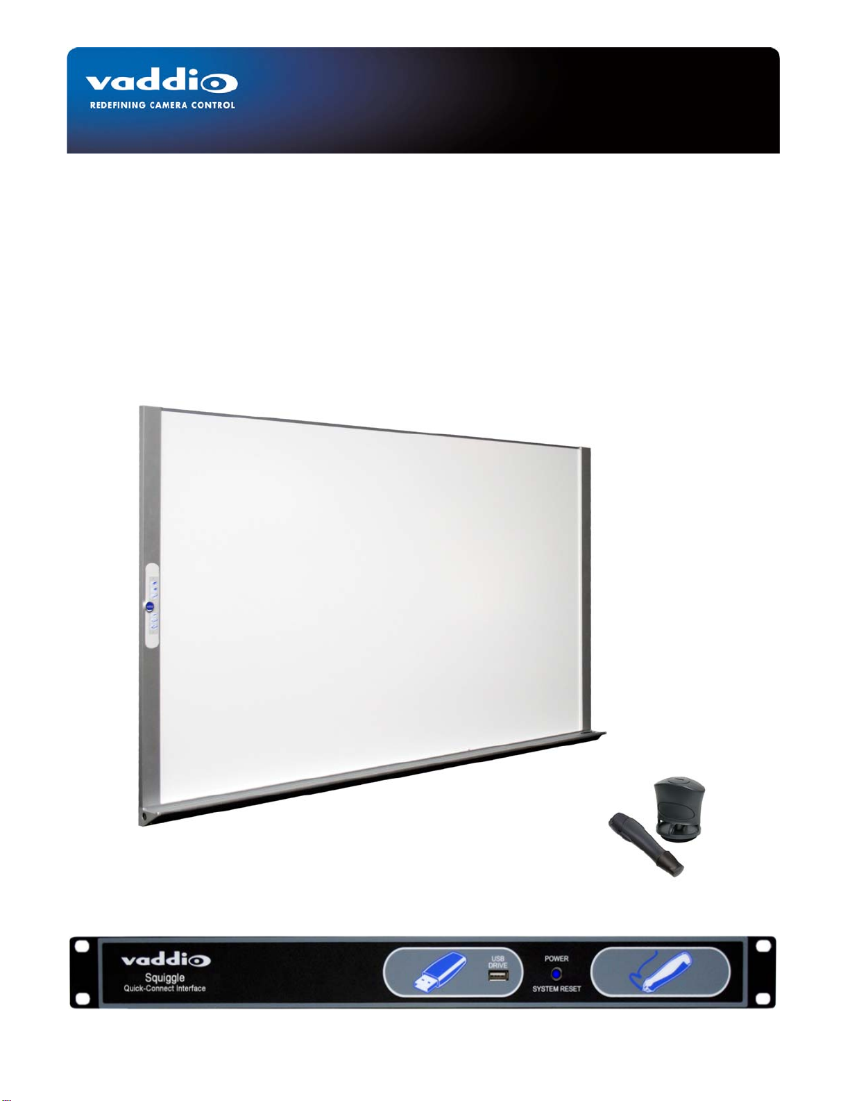
Figure Group 1: Vaddio 4’ x 6’ Squiggle Board, Front
Panel of the Squiggle Quick-Connect Interface
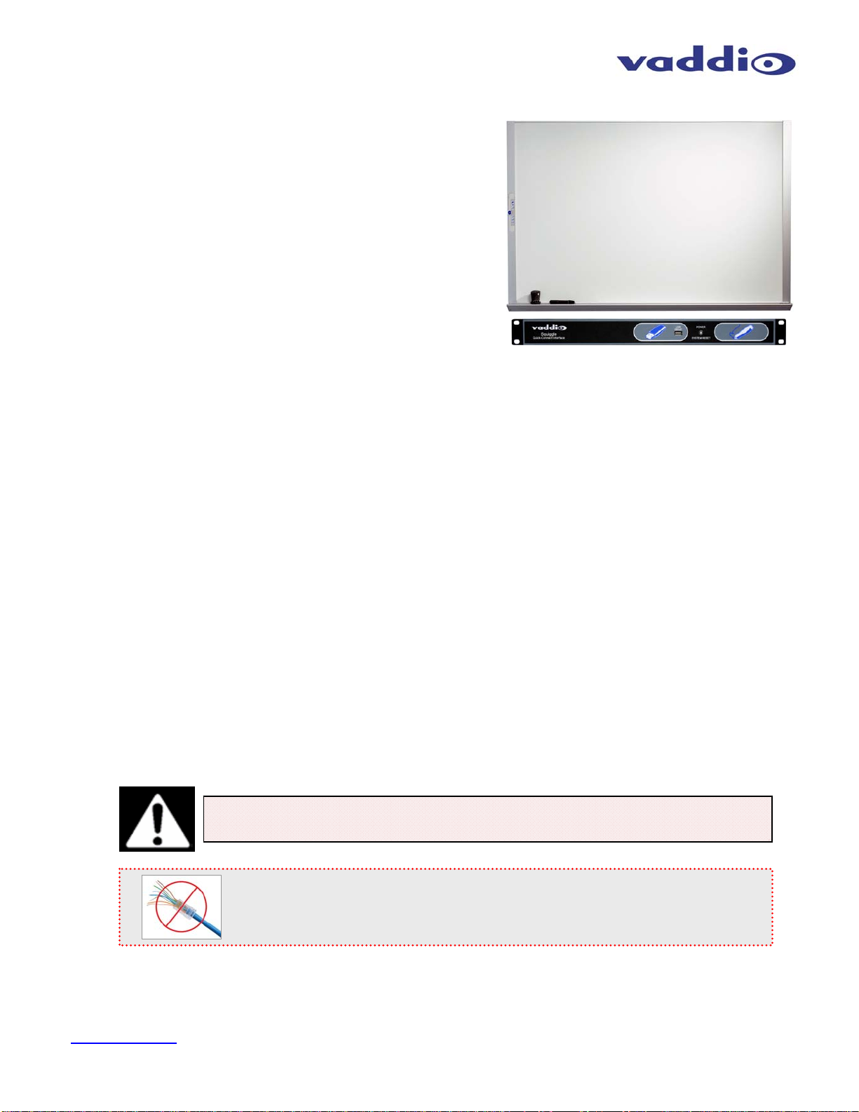
Use only the power supply provided with the system. Use of any unauthorized
power supply will void any and all warranties.
Please do not use “pass-thru” type RJ-45 connectors. These pass-thru type connectors do not
work well for professional installations and can be the cause of intermittent connections which
can result in the RS-232 control line failing and locking up, and/or compromising the HSDS™
signals. For best results please use standard RJ-45 connectors and test all cables for proper
pin-outs prior to use and connection to Vaddio product.

Squiggle Board
Squiggle Board Manual 342-0069 Rev. C Page 4 of 16
UNPACKING:
Carefully remove the device and all of the parts from the packaging and identify the following parts:
•One (1) Squiggle whiteboard (4’ x 6’ or 4’ x 8’) with Digital Control Panel installed
•One (1) Squiggle Quick-Connect Interface
•One (1) Black Digital Marker Sleeve
•One (1) Black Marker
•One (1) Digital Eraser
•One (1) PowerRite 12 VDC, 3.0 Amp Power Supply
•One (1) AC Cord Set for North America or International (UK and Euro)
•Whiteboard Hardware Mounting Kit
•Documentation and Manual
Digital Control Panel:
The basic system controls on the Squiggle Board Digital Control Panel are as follows:
1) Ultra Sonic Sensors (top & bottom): Detects marker movements on the whiteboard.
2) One-Touch Image Save Button: When a flash drive is plugged into the front panel of the Quick-Connect,
pressing this button will save a copy of what has been drawn on the whiteboard as a 1280x720 JPEG image.
3) Erase Button: To erase all content on the Squiggle Board video output, simply press this button. Pressing
this button a second time will recall all video content written on the board from the last time it was erased, as
long as no other pen strokes are recorded.
4) Calibrate Button: Allows the user to calibrate the writing area of the video whiteboard.
5) Power Indicator & IR Sensor: The ring is illuminated when the device is powered on. The sensor detects IR
emitted from the Marker Sleeve, and triangulates the marker movements with the ultra sonic sensors.
6) Pen Width: The line thickness is adjustable in three (3) line widths (thin, medium and thick). Line widths can
be mixed on any drawing being displayed on the video output.
③
④
②
⑥
①
⑤
Squiggle Board
R
µѵ
-
(1/2g
µѵ
)R + g
µѵ
Λ= (8πG/c
4
)T
µѵ
The constant Λis the cosmological constant;
the energy conservation law is unaffected
G
µѵ
= R
µѵ
-1/2(R g
µѵ)
G
µѵ
= (8πG/c
4
)T
µѵ
Commonly written as:
G
µѵ
= 8πT
µѵ

Squiggle Board
Squiggle Board Manual 342-0069 Rev. C Page 5 of 16
Squiggle Quick-Connect Interface Front Panel (left to right):
1) USB Drive Port: The USB port on the front panel allows the user to plug in any standard FAT32 or Fat16 USB
drive to store content written on the whiteboard. Simply press the One-TOUCH Image Save icon on the Digital
Control Panel (see previous page) and the content written on the whiteboard will be saved to the USB drive. A
confirmation of the saved content will be displayed on the video output. All information is saved as a 1280 x
720 JPEG image.
2) Power Indicator / System Reset Button: When the Squiggle Quick-Connect Interface is turned on, the
POWER indicator light illuminates. It is not a power switch. This button also serves as a SYSTEM RESET
button. Pressing the button will reset the system from boot up.
Rear Panel Connections and Controls (Left to Right):
1) Power Supply Input: 12VDC, 3.0 Amp power supply on a 5.5mm OD x 2.5mm ID connector.
2) Whiteboard RJ-45: Power and data transmitted to and from the Whiteboard via Cat. 5e cabling.
3) Ethernet on RJ-45: Ethernet port is reserved for future use and not active at this time.
4) Settings: The Squiggle Quick-Connect has a 5-position dip switch for setting HD or SD resolution, refresh
rate, test bars and switches available for future settings.
5) Video Outputs: Three video outputs; DVI-D, YPbPr HD and CVBS (composite), are available on the
Squiggle Quick-Connect Interface.
•The DVI-D and YPbPr outputs are simultaneous outputs and are at a resolution of 720p/59.94 or
720p/50 which allows the Squiggle Board to be connected to a variety of video devices such as Vaddio
switchers/mixers, videoconferencing codecs, monitors and other third-party video devices.
•The SD Video can be chosen instead of the HD DVI-D and YPbPr outputs and output SD resolutions of
480i/NTSC and 576i/PAL.
NOTE: If the SD composite video output is chosen instead of the HD outputs, a dip switch setting is
changed to allow the SD output to be active. The HD outputs are not active when the SD video is
chosen with the dip switch. Conversely, the SD video out is not active when the HD video is chosen.
Optional Accessories for Squiggle Board:
①②
③④
②
①⑤
Colored Digital Sleeves
(998-5440-030) Whiteboard Cleaner
(998-5440-020)
Standard Whiteboard
Eraser
(998-5440-010)
Replacement Bullet
Tip Markers
(998-5440-040)

Squiggle Board
Squiggle Board Manual 342-0069 Rev. C Page 6 of 16
Installation Notes and Procedures
Before Installing:
•Locate the whiteboard location paying close attention to whiteboard height requirements, location in the room,
lighting conditions, and checking for in-wall obstructions.
•Keep other IR or Ultrasonic devices and reflective surfaces away from the whiteboard location.
•The 4’ x 6’ whiteboard is supplied with 8-clips & screws and the 4’ x 8’ whiteboard is supplied with 10-clips and
screws for mounting purposes, as well as spiral drywall anchors and 8-32 x 1.25” screws.
Step 1: Before installing the Squiggle Board, run the Cat-5e cabling from the equipment head-end to where the
whiteboard is to be installed. Make sure that there is enough excess cable to run to the bottom left corner of the
whiteboard, where the USB extender is located.
Step 2: Attach the bottom mounting angle clips to the wall with the required wall fasteners at the proper marker
tray height, as specified by the customer, or room requirements.
Note: Vaddio supplies necessary hardware for mounting the whiteboard to standard drywall. Installation
of the whiteboard on masonry or other walls requires specialized mounting screws, available through
construction hardware suppliers. Ensure that all clips/hangers are level, when attaching them to the wall.
Step 3A: If the Cat-5e is to be run inside the wall cavity (drywall) to the location where the whiteboard is to be
installed, then measure out and drill a hole through the drywall for the Cat-5e to be run through corner below the
Digital Control Panel on the left side of the whiteboard. See the drawing of the Squiggle Board back below for
measurements.

Squiggle Board
Squiggle Board Manual 342-0069 Rev. C Page 7 of 16
Installation (continued):
Step 3B: If the Cat. 5e cable is to be surfaced mounted, install Panduit® or some other type of conduit (not
included) on the wall to the corner below the electronic receiver side of the whiteboard. On the marker tray end
cap, there is a 7/8” grommet hole to easily terminate the cable to the USB interface, which is installed in the marker
tray. If the cable can also run along the floor as long as it is secured and does not become a hazard to anyone that
would come in contact with the cabling.
Step 4: To install the top angle clips, measure 4’ (1.22m) from the slotted side of the bottom angle clip. Attach the
top clips to the wall. Tighten the screws and clips, but DO NOT TIGHTEN completely.
Step 5: Install the whiteboard by placing the bottom of the board on the top of the bottom mounting clip. It is
recommended that at least two (2) people are involved with lifting and setting the whiteboard in place. Press the
whiteboard firmly to the wall and install screws furnished through the bottom clips of the board only. Pre-drilling the
holes may help the speed of the installation process.
Step 6: After installing the screws into the bottom of the whiteboard, use a wooden block to tap the mounting clips
down tight against the top of the whiteboard trim, and install screws.
Step 7: If protective film covers the whiteboard surface, then remove it. CLEAN THE WHITEBOARD SURFACE
BEFORE USE. See cleaning instructions. The whiteboard is easier to erase after it has been cleaned.
IMPORTANT NOTE:
Check all Cat-5e cables for continuity in advance of the final connection. See disclaimer on page 3.
Step 8 - Finishing Up the connections:
Below the Digital Control Panel, there is a cable in the side rail that runs down to the marker tray on the left side.
Remove the left plastic marker rail end-cap with the 7/8” grommet to make the connections, as this is where a USB
Gender Changer and the USB to Cat. 5e plug QC-Extender/Regulator is located.
•Attach the USB B-Female from the whiteboard control panel to the USB B-Male to A-Female adapter
provided.
•Attach the QC-Extender A-Male to the A-Female side of the adapter.
•Finally, attach the Cat. 5e to the RJ-45 jack on the QC-Extender.
•At the head end Squiggle Quick-Connect Interface, plug in the Cat. 5e cable into the RJ-45 jack labeled
TO VIDEO WHITEBOARD.
•Re-attach the plastic end cap and make sure to clean the surface BEFORE using it. Cleaning it first
makes it easier to erase.
•Connecting the Squiggle Board to the Quick-Connect Interface:
Attached
USB cable &
B-Female
Connector
USB B-Male
to A-Female
Adapter
QC-Extender
USB A-Male with
PCB Internal and
RJ-45 Jack Out
•
Connect the Adapter and Extender together
and run the Cat-5e to the Quick-Connect Unit.
•Tuck the Adapter and Extender back into the
marker tray and replace the plastic end cap.
Cat. 5e
Power & Data

Squiggle Board
Squiggle Board Manual 342-0069 Rev. C Page 8 of 16
Step 9 - The “Seems Obvious” Step: Put the provided batteries in the Digital Pen Sleeve and the Digital Eraser.
•Pen: Twist the pen sleeve cap counter-clockwise and put two (2) CR2032 batteries provided, stacked
positive (+) side up, and return the cap. Put the bullet nose black marker in the pen sleeve.
•Eraser: With a coin, twist the digital eraser cap counter-clockwise and put two (2) CR2032 batteries
provided, stacked positive (+) side up and return the cap.
Step 10 - Setting the 5-Position Dip Switch:
The Squiggle Quick-Connect Interface has a 5-position dip switch accessible on the rear panel. The switch settings
are on the following table:
Example Set-ups:
•HD, 720p/59.94, Color Bars Off: SW1 = UP, SW2 = UP, SW5 = UP
•SD, 480i/NTSC, Color Bars Off: SW1 = DN, SW2 = UP, SW5 = UP
•HD, 720p/50, Color Bars Off: SW1 = UP, SW2 = DN, SW5 = UP
•SD, 576i/PAL, Color Bars Off: SW1 = DN, SW2 = DN, SW5 = UP
Notes: Default Position for all Switches is UP = HD, 720p/59.94, SMPTE Color Bars OFF.
Switches 3 and 4 are not used and are for future use.
The Color Bars are a video testing convenience only.
Using the Squiggle Board:
Upon connection and powering up the Squiggle Quick-Connect Interface, the System will boot up and the Vaddio
splash screen will be seen on the 720p or SD display device.
Automatically, the Software Version number, MAC address and the legal notices are displayed briefly. The MAC
will be needed as the Ethernet functions are added to the software and for technical support.
Dip
Switch 1 2 3 4 5
UP HD HD - 720p/59.94 or
SD - 480i/29.97 - NTSC - -
SMPTE Color
Bars OFF
Down SD HD - 720p/50 or
SD - 576i/25 - PAL - -
SMPTE Color
Bars ON
UP - ↑
Down - ↓
5-Position Dip Switch
Accessible from the rear
panel of the Quick-Connect
Interface

Squiggle Board
Squiggle Board Manual 342-0069 Rev. C Page 9 of 16
Using the Squiggle Board (continued): The system will load the default 4’ x 6’ calibration size. It is
recommended that if you have a 4’ x 6’ whiteboard, perform the calibration process anyway. The 4’ x 8’
whiteboard, or any other size, requires calibration. The process to calibrate the system is as follows:
1) Touch the Calibration button on the Digital Control Panel and the following screen is displayed.
The prompt, “Using the Electronic whiteboard marker, tap each highlighted target” will be displayed. Start in the
upper left corner and proceed tapping the targets from top to bottom in the order shown above. When the
calibration is complete, the system is ready for use.
If there is an unintentional mistake during calibration, simply touch the calibration button again to stop the process.
To restart calibration, touch the button again.
To Save the Whiteboard Content to USB Drive:
Put a flash drive into the Squiggle Quick-Connect front panel USB port. This port supports only FAT32 or FAT16
formatted drives. Touch the Flash Drive Icon on the Digital Control Panel and the system will show the prompt
“Saving image, Please wait…”
After the image is saved the following prompt is displayed briefly:
At this point, the drive may be removed or left in the USB port for future content to be saved. The image saved can
be loaded into any computer device that can accept the FAT32/16 file format and view the image as a JPEG.
Important Note:
Remember to put two (2)
CR2032 batteries into the
Digital Pen Sleeve, stacked
with the positive (+) sides up,
to allow the pen to calibrate
the system. See Step 9 of
the Installation Procedures.

Squiggle Board
Squiggle Board Manual 342-0069 Rev. C Page 10 of 16
FOR BEST RESULTS:
Pen & Eraser Etiquette:
The Squiggle Board Pen Holder is the device that is tracked
by the ultra sonic sensors and the IR sensor. In order to
achieve the best results, adhere to the following guidelines.
•Always write with the pen tip making contact at a 90°
angle (perpendicular) to the whiteboard surface.
•Carefully and firmly press the pen and pen holder to the
whiteboard surface. It is a firm contact that engages the
sonic transmitters and allows the pens to be tracked.
Pressing too lightly with the pen may result in line drop
outs.
•Use bullet point, regular markers for best results. The low odor markers are eco-friendly, however these eco
markers are difficult to erase as the oils are removed to prevent the odor. Normal bullet nosed markers work
best.
•When pressing the Digital Maker Sleeve and Pen at a 90° angle, a slight buzzing sound may be audible. This
is really normal. Most people will check the battery by holding it up to their ear - but please do not insert the
pen in your or anybody else’s ear.
•An indication of a possible low battery condition in the Digital Pen Sleeve or Digital Eraser is the inability to
write/erase on the far end of the whiteboard opposite from the Digital Control Panel.
•When returning the pen cap, the pen can be triggered if handled improperly. The whiteboard sensors can
receive the pulse and leave a dot or very short line on the video image. If this is undesirable, turn away from
the whiteboard during a session and then put the pen cap on the marker holder.
•Loose clothing such as cuffs or puffy “pirate sleeves” can block the pen transmitters and cause drop outs and
less than acceptable results.
•The porcelain over steel whiteboard surface is magnetic. Please do not attach papers to the whiteboard
surface with a magnet. The paper will interfere with the pen tracking and may produce some wicked-awful
lines, again with mostly undesirable effects.
•The Squiggle Board uses ultra sonic and IR technology. There are some devices in any presentation
environment that may cause interference with normal operation. Try to mitigate interference between all
devices using ultra sonic or IR technology for best results. The resonating induction inhibitor will cancel most
stray interference, but certainly not all of it.
•If colored pen sleeves are purchased as an option, the color ring of the marker sleeve should be matched to the
pen color to avoid multiphasic polarizing regeneration. The color of the marker sleeve ring will match the color
of the video displayed.
•The Digital Eraser works like the Digital Pens. To selectively erase portions of the whiteboard content, press
the eraser firmly against the whiteboard at a 90° angle (perpendicular) to engage the ultra sonic and IR
transmitters. If there are pesky line remnants on the video after trying to erase the whole whiteboard with the
Digital Eraser, these are a result of not holding the eraser at a perfect 90° angle to the whiteboard surface.
To do a mass erase job, first touch the Erase Button on the Digital Control Panel and whip out a
sizeable regular whiteboard eraser device and rub down the whole whiteboard. Remember to
clean the surface with high quality Whiteboard Cleaner (Nettoyant de Tableau Blanc) to clean and
refresh the whiteboard periodically. Cleaning will make it easier to erase…really.
Erase Button

Squiggle Board
Squiggle Board Manual 342-0069 Rev. C Page 11 of 16
Sample Wiring Diagram of Squiggle Board to Peripheral Devices:
General Specifications:
Squiggle Boards
Part Numbers 999-5446-000: 4’ x 6’ (1.22m x 1.83m) North America
999-5446-001: 4’ x 6’ (1.22m x 1.83m) International
999-5448-000: 4’ x 8’ (1.22m x 2.03m) North America
999-5448-001: 4’ x 8’ (1.22m x 2.03m) International
Squiggle Board Physical Specs
Surface Porcelain-on-steel
Trim Aluminum, with marker tray
Weight:
Packed Weight
4’ x 6’ (1.22m x 1.83m): 100 lbs (45.454545 kg)
4’ x 8’ (1.22m x 2.03m): 125 lbs (56.818181 kg)
Squiggle Quick-Connect Interface
Connectors Power Connector: 5.5mm OD x 2.5mm ID
Whiteboard RJ-45: Supplies power and Serial Data to Whiteboard Digital Control Panel
Ethernet RJ-45: Reserved for future use
Video Outputs: DVI-D and DE-15 for YPbPr-HD and BNC Connector for SD video
Settings Switches For setting HD or SD video, Refresh Rate, Color Bars and for Future Enhancements
CAT-5 Cable Distance Up to 100’ (30.5m)
Flash Drive Format FAT32 or FAT16
Average JPG File Size 200 KB to 300 KB Depending on Content Density
Power Supply 12 VDC, 3.0 Amp
Dimensions 1-RU Rack Mount - 1.72” (43.69mm) H x 18.93” (480.82mm) W x 6” (152.4mm) D
Weight 3.2 lbs. (1.45329107kg) - Approximate Weight
DVI-D
S
q
ui
gg
le Board with Di
g
ital Control Panel
Cat 5e Cable
(Up to 100’ / 30.48m)
Squiggle Board
Quick-Connect Interface
DVI-D 720p
(HDMI with
Adapter Cable)
Videoconferencing Codec
Large Format HD
Monitor or HD
Projector
YPbPr 720
p
R
µѵ
-
(1/2g
µѵ
)R + g
µѵ
Λ= (8πG/c
4
)T
µѵ
The constant Λis the cosmological constant;
the energy conservation law is unaffected
G
µѵ
= R
µѵ
-1/2(R g
µѵ)
G
µѵ
= (8πG/c
4
)T
µѵ
Commonly written as:
G
µѵ
= 8πT
µѵ
R
µѵ
-
(1/2g
µ
ѵ
)R + g
µ
ѵ
Λ= (8πG/c
4
)T
µ
ѵ
The constant Λis the cosmological constant;
the energy conservation law is unaffected
G
µѵ
= R
µѵ
-1/2(R g
µѵ)
G
µѵ
= (8πG/c
4
)T
µ
ѵ
Commonly written as:
G
µѵ
= 8πT
µѵ
R
µѵ
-
(1/2g
µ
ѵ
)R + g
µ
ѵ
Λ= (8πG/c
4
)T
µ
ѵ
The constant Λis the cosmological constant;
the energy conservation law is unaffected
G
µѵ
= R
µѵ
-1/2(R g
µѵ)
G
µѵ
= (8πG/c
4
)T
µ
ѵ
Commonly written as:
G
µѵ
= 8πT
µѵ
USB Flash Drive

Squiggle Board
Squiggle Board Manual 342-0069 Rev. C Page 12 of 16
Squiggle Board Dimensions:

Squiggle Board
Squiggle Board Manual 342-0069 Rev. C Page 13 of 16
Compliance and CE Declaration of Conformity
FCC Part 15 Compliance
This equipment has been tested and found to comply with the limits for a Class A digital device, pursuant to Part 15
of the FCC Rules. These limits are designed to provide reasonable protection against harmful interference when
the equipment is operated in a commercial environment. This equipment generates, uses, and can radiate radio
frequency energy and, if not installed and used in accordance with the instruction manual, may cause harmful
interference to radio communications. Operation of this equipment in a residential area is likely to cause harmful
interference in which case the user will be required to correct the interference at his/her own expense.
Operation is subject to the following two conditions: (1) This device may not cause interference, and (2) This device
must accept any interference including interference that may cause undesired operation of the device.
Changes or modifications not expressly approved by Vaddio can affect emission compliance and could void the
user’s authority to operate this equipment.
ICES-003 Compliance
This digital apparatus does not exceed the Class A limits for radio noise emissions from digital apparatus set out in
the Radio Interference Regulations of the Canadian Department of Communications.
Le présent appareil numérique n’emet pas de bruits radioélectriques dépassant les limites applicables aux
appareils numeriques de la classe A préscrites dans le Règlement sur le brouillage radioélectrique édicte par le
ministère des Communications du Canada.
European Compliance
This product has been evaluated for Electromagnetic Compatibility under the EMC Directive for Emissions and Immunity and
meets the requirements for a Class A digital device. In a domestic environment this product may cause radio interference in
which case the user may be required to take adequate measures.
Standard(s) To Which Conformity Is Declared:
EMC Directive 2004/108/EC
EN 55022 A: 2006 + A1 2007 (CISPR 22:2005/A1:2005) Conducted and Radiated Emissions
EN 55024: 1998 + Amendments A1: 2001 + A2: 2003 - Electromagnetic Compatibility - Immunity
EN 61000-4-2 Electrostatic Discharge
EN 61000-4-3 Radiated Immunity
EN 61000-4-4 Electrical Fast Transients
EN 61000-4-5 Surge Immunity
EN 61000-4-6 Conducted Immunity
EN 61000-4-8 Power Frequency Magnetic Field
EN 61000-4-11 Voltage Dips, Interrupts and Fluctuations

Squiggle Board
Squiggle Board Manual 342-0069 Rev. C Page 14 of 16
Warranty Information:
Hardware* Warranty - One year limited warranty on all parts. Vaddio warrants this product against defects in
materials and workmanship for a period of one year from the day of purchase from Vaddio. If Vaddio receives
notice of such defects during the warranty period, they will, at their option, repair or replace products that prove to
be defective.
Exclusions - The above warranty shall not apply to defects resulting from: improper or inadequate maintenance by
the customer, customer applied software or interfacing, unauthorized modifications or misuse, operation outside the
normal environmental specifications for the product, use of the incorrect power supply, improper extension of the
power supply cable or improper site operation and maintenance.
Vaddio Customer Service - Vaddio will test, repair, or replace the product or products without charge if the unit is
under warranty and is found to be defective. If the product is out of warranty, Vaddio will test then repair the product
or products. The cost of parts and labor charge will be estimated by a technician and confirmed by the customer
prior to repair. All components must be returned for testing as a complete unit. Vaddio will not accept responsibility
for shipment after it has left the premises.
Vaddio Technical support - Vaddio technicians will determine and discuss with the customer the criteria for repair
costs and/or replacement. Vaddio Technical Support can be contacted through one of the following resources: e-
Return Material Authorization (RMA) number - Before returning a product for repair or replacement, request an
RMA from Vaddio’s technical support. Provide a technician with a return phone number, e-mail address, shipping
address, and product serial numbers and describe the reason for repairs or returns as well as the date of purchase
and proof of purchase. Include your assigned RMA number in all correspondence with Vaddio. Write your
assigned RMA number on the outside of the box when returning the product. All products returned for credit are
subject to restocking charges, without exceptions.
Voided Warranty - The warranty does not apply if the original serial number has been removed or if the product
has been disassembled or damaged through misuse, accident, modifications, or unauthorized repair. Cutting the
power supply cable on the secondary side (low voltage side) to extend the power to the device (camera and/or any
device) voids the warranty for that device.
Shipping and Handling - Vaddio will not pay for inbound shipping transportation or insurance charges or accept
any responsibility for laws and ordinances from inbound transit. Vaddio will pay for outbound shipping,
transportation, and insurance charges for all items under warranty but will not assume responsibility for loss and/or
damage by the outbound freight carrier.
• If the return shipment appears damaged, retain the original boxes and packing material for inspection by the
carrier. Contact your carrier immediately.
Products Not Under Warranty - Payment arrangements are required before outbound shipment for all out of
warranty products.
*Vaddio manufactures its hardware products from parts and components that are new or equivalent to new in accordance with industry standard practices.
Other General Information:
Care and Cleaning
Do not attempt to take this product apart at any time. There are no user-serviceable components inside.
•Do not spill liquids in the Squiggle Quick-Connect Interface, Digital Control Panel or Marker Tray
•Keep this device away from food, squirt guns, liquid in general, other IR and Ultrasonic devices.
•For smears or smudges on the railing and aluminum, wipe with a clean, soft cloth with a light duty household cleaner
that leaves no residue. Use a high quality whiteboard cleaner on the surface for best results. Clean periodically to
keep the whiteboard easy to erase.
•Do not use any abrasive chemicals.
Operating and Storage Conditions:
Do not store or operate the device under the following conditions:
•Temperatures above 40°C (104°F) or temperatures below 0°C (32°F)
•High humidity, condensing or wet environments, in inclement weather on in a swimming pool
•Dusty environments or outside in direct sunlight
•Under severe vibration (i.e. in a 1985 Yugo)
•In a bear cave or near a Raccoon stream

Squiggle Board
Squiggle Board Manual 342-0069 Rev. C Page 15 of 16
Inside Back Cover (blank)

Squiggle Board
Squiggle Board Manual 342-0069 Rev. C Page 16 of 16
9433 Science Center Drive, Minneapolis, MN 55428
Toll Free: 800-572-2011 ▪Phone: 763-971-4400 ▪FAX: 763-971-4464
www.vaddio.com
©2011 Vaddio - All Rights Reserved. Reproduction in whole or in part without written permission is prohibited. Specifications and pricing are subject to
change without notice. Vaddio, Quick-Connect, PowerRite, HSDS and EZCamera are registered trademarks of Vaddio. All other trademarks are property
of their respective owners. Document Number 342-0069 Rev. C.
This manual suits for next models
3
Table of contents
Popular Whiteboard manuals by other brands

Hitachi
Hitachi StarBoard FX-79E2 user guide

Great Little Trading
Great Little Trading Family Blackboard L3022 manual

Ricoh
Ricoh D6500 Firmware upgrade guide

EGAN
EGAN A-Frame VersaMobile Assembly & installation

Parker
Parker 70-134 Series Assembly instructions

eInstruction
eInstruction Interwrite Mobi user guide