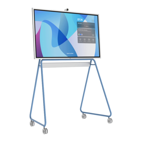
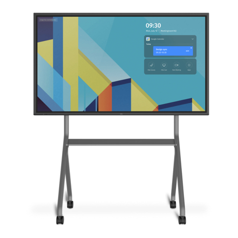
Vibe V55N203 Series User manual

Vibe
User Manual
(Please read this manual before operation)

ii
Safety Instructions
Safety precautions and maintenance
WARNING: Use of controls, adjustments or procedures other than those specified in this
documentation may result in exposure to shock, electrical hazards and/or mechanical
hazards.
Read and follow these instructions when connecting and using your display:
Operation:
• Keep the display out of direct sunlight and open flames, hot appliances, or any other heat sources.
• Remove any object that could fall into ventilation holes or prevent proper cooling of the display’s
electronics.
• Do not block the ventilation holes on the Vibe.
• When positioning the display, make sure the power plug and outlet are easily accessible.
• When turning off the display by detaching the power cord, wait 6 seconds before re-attaching the
power cord for normal operation.
• Ensure the use of an approved power cord at all times. If your power cord is missing, please contact
your local service center.
• Do not subject the display to strong vibration or high impact during operation.
• Avoid dropping the display during operation or transportation.
• This apparatus is intended to be supported by a UL Listed Wall Mount Bracket or equivalent.
Maintenance:
• To protect your display from possible damage, do not put excessive pressure on the LCD panel. When
moving your display, hold the frame to lift; do not lift the display by placing your hand or fingers on
the LCD panel.
• Unplug the display if you are not going to use it for an extensive period of time.
• Unplug the display if you need to clean it with a slightly damp cloth. The screen may be wiped with
a dry cloth when the power is off. Never use organic solvent, such as alcohol, or ammonia-based
liquids, to clean your display.
• To avoid the risk of shock or permanent damage to the hardware, do not expose the display to dust,
rain, water, or a moist environment.
• If your display becomes wet, wipe it with a dry cloth as soon as possible.
• If a foreign substance or water gets in your display, turn the power off immediately and disconnect
the power cord. Then remove the foreign substance or water and send the unit to the maintenance
center.
• Do not store or use the display in locations exposed to heat, direct sunlight or extreme cold.
• In order to maintain the best performance of your display and ensure a longer lifetime, we strongly
recommend using the display in a location within the following temperature and humidity ranges:
-Temperature: 0-40°C 32-104°F
-Humidity: 20-80% RH
-Altitude: 5000m

iii
• The forward tilt of the product will affect the touch effect. The suggested installation
angle is 0o~5o.0 ~5
IMPORTANT: Always activate a moving screen saver program when you leave your display unattended.
Always activate a periodic screen refresh application if the unit will display unchanging static content.
Uninterrupted display of still or static images over an extended period may cause “burn in”, also known
as “after-imaging” or “ghost imaging”, on your screen. This is a well-known phenomenon in LCD panel
technology. In most cases, the image will disappear gradually after the power has been switched off.
WARNING: Severe “burn-in” symptoms will not disappear and cannot be repaired. This is not covered
under the terms of your warranty.
Service:
• The casing cover should only be opened by qualified service personnel.
• If there is any need for repair or integration, please contact your local service center.
If your display does not operate normally, having followed the instructions in this document,
please contact a technician or your local service center.
Important Safety Instructions
1. Read these instructions.
2. Keep these instructions.
3. Heed all warnings.
4. Follow all instructions.
5. Do not use this apparatus near water.
6. Clean only with dry cloth.
7. Do not block any ventilation openings. Install in accordance with the manufacturer’s instructions.
8. Do not install near any heat sources such as radiators, heat registers, stoves, or other apparatus
(including amplifiers) that produce heat.
9. Do not defeat the safety purpose of the polarized or grounding-type plug. A polarized plug has two
blades, one wider than the other. A grounding type plug has two blades and a third grounding prong.
The wide blade or the third prong are provided for your safety. If the provided plug does not fit into
your outlet, consult an electrician for replacement of the obsolete outlet.
10.Protect the power cord from being walked on or pinched particularly at plugs, convenience receptacles,
and the point where they exit from the apparatus.
11. Only use attachments/accessories specified by the manufacturer.
12.Use only with the cart, stand, tripod, bracket, or table specified by the manufacturer, or sold with the
apparatus. When a cart is used, use caution when moving the cart/apparatus combination to avoid
injury from tip-over. Use with other (carts, stands, or carriers) may result in instability causing injury.
13.Unplug this apparatus during lightning storms or when unused for long periods.
14.Refer all servicing to qualified service personnel. Servicing is required when the apparatus has been
damaged in any way, such as if the power-supply cord or plug is damaged, liquid has been spilled or
objects have fallen into the apparatus, the apparatus has been exposed to rain or moisture, does not
operate normally, or has been dropped.
iii

iv
ESD Warnings
When user close to the monitor, it may cause the equipment discharge and reboot to the display of main
menu.
Warning:
This equipment is compliant with Class A of EN55032/CISPR 32. Operation of this equipment in a
residential environment could cause radio interference.
Federal Communications Commission (FCC) Notice (U.S. Only)
This equipment has been tested and found to comply with the limits for a Class A digital
device, pursuant to part 15 of the FCC Rules. These limits are designed to provide reasonable
protection against harmful interference when the equipment is operated in a commercial
environment. This equipment generates, uses and can radiate radio frequency energy and,
if not installed and used in accordance with the instruction manual, may cause harmful
interference to radio communications. Operation of this equipment in a residential area is
likely to cause harmful interference in which case the user will be required to correct the
interference at his own expense.
Changes or modifications not expressly approved by the party responsible for compliance
could void the user’s authority to operate the equipment.
Use only an RF shielded cable that was supplied with the display when connecting this display to a
computer device.
To prevent damage which may result in fire or shock hazard, do not expose this appliance to rain or
excessive moisture.
This device complies with Part 15 of the FCC Rules. Operation is subject to the following
two conditions: (1) This device may not cause harmful interference, and (2) this device
must accept any interference received, including interference that may cause undesired
operation.
End-of-Life Disposal
Your new Public Information Display contains materials that can be recycled and reused. Specialized
companies can recycle your product to increase the amount of reusable materials and to minimize the
amount to be disposed of.
Please find out about the local regulations on how to dispose of your old display from your local dealer.
(For customers in Canada and U.S.A.)
This product may contain lead and/or mercury. Dispose of in accordance to local-state and federal
regulations. For additional information on recycling, contact www.eia.org (Consumer Education Initiative)
Waste Electrical and Electronic Equipment--WEEE
Attention users in United States:
Please dispose of the product according to all Local, State and Federal Laws. For disposal or recycling
information, contact: www.mygreenelectronics.com or www.eiae.org.
iv

v
End of Life Directives--Recycling
Your new Public Information Display contains several materials that can be recycled for
new users.
Please dispose of according to all Local, State, and Federal laws.
Disposal of Waste Equipment by Users in Private Househould in the European
Union.
This symbol on the product or on its packaging indicates that this product
must not be disposed of with your other household waste. Instead it is your
responsibility to dispose of your waste equipment by handing it over to a
designated collection point for the recycling of waste electrical and electronic
equipment. The separate collection and recycling of your waste equipment at
the time of disposal will help to conserve natural resources and ensure that it is
recycled in a manner that protects human health and the environment. For more
information about where you can drop off your waste equipment for recycling,
please contact your local city office, your household waste disposal service or the
shop where your purchased the product.
This radio transmitter has been approved by Industry Canada.
This Class B digital apparatus complies with Canadian standard CAN ICES-003(B)/NMB-003(B). This device
complies with Industry Canada License exempt RSS standard(s). Operation is subject to the following
two conditions. This device may not cause interference and (2) this device must accept any interference,
including interference that may cause undesired operation of the device.
This equipment complies with ISED radiation exposure limits set forth for an uncontrolled environment.
This equipment should be installed and operated with a minimum distance of 20cm between the radiator
& your body.
Stability Hazard
The product may fall, causing serious personal injury or death. To prevent injury, this product must
be securely attached to the floor/wall in accordance with the installation instructions. Many injuries,
particularly to children, can be avoided by taking simple precautions such as:
ALWAYS use cabinets, stands, or installation methods recommended by the manufacturer of the product.
ALWAYS use furniture that can safely support the product.
ALWAYS ensure the product is not overhanging the edge of the supporting furniture.
ALWAYS educate children about the dangers of climbing on furniture to reach the product or its controls.
ALWAYS route cords and cables connected to your product so they cannot be tripped over, pulled or
grabbed.
NEVER place a product in an unstable location.
NEVER place the product on tall furniture (for example, cupboards or bookcases) without anchoring both
the furniture and the product to a suitable support.
NEVER place the product on cloth or other materials that may be located between the product and
supporting furniture.
NEVER place items that might tempt children to climb, such as toys and remote controls, on the top of
the product or furniture on which the product is placed.
If the existing product is going to be retained and relocated, the same considerations as above should be
applied.

vi
When using the display, fasten the LCD to a wall using a cord or chain that can support the weight of the
monitor in order to prevent the monitor from falling.
Installing must be done by a qualified technician. Please contact your supplier for more information.
Cord or chain
M6 Screw
Clamp
Release the screws then
fix the clamp.
or

vii
Table of Contents
1. Unpacking and Installation............................................................................................................1
1.1. Unpacking....................................................................................................................................................... 1
1.2. Package Contents........................................................................................................................................ 1
1.3. Installation Notes....................................................................................................................................... 1
2. Stand Installation (Optional)........................................................................................................2
2.1. Vibe Assembly Notes................................................................................................................................2
2.2. Installing the Stand...................................................................................................................................3
3. Parts and Functions......................................................................................................................... 7
3.1. Input/Output................................................................................................................................................7
3.2. Stylus................................................................................................................................................................7
4. Touch Control....................................................................................................................................8
4.1. Draw & Erase with Vibe Stylus.............................................................................................................8
4.2. Canvas Operation by Fingertips..........................................................................................................8
4.3. Other Operations........................................................................................................................................8
5. Pixel Defect Policy...........................................................................................................................9
5.1. Pixels and Subpixels.................................................................................................................................9
5.2. Types of Pixel Defects + Dot Definition ..........................................................................................9
5.3. Dark Dot Defects ........................................................................................................................................9
5.4. Proximity of Pixel Defects .....................................................................................................................9
5.5. Pixel Defect Tolerances..........................................................................................................................10
5.6. MURA .............................................................................................................................................................10
6. Cleaning and Troubleshooting....................................................................................................11
6.1. Cleaning......................................................................................................................................................... 11
6.2. Troubleshooting........................................................................................................................................12
7. Technical Specifications............................................................................................................... 13

1
This User Manual applies to the Mode Numbers as below:
V55N203W, V55N203EU, V55N203EW, V55N203*
The user interface is subject to change. Please refer to the actual machine for user interactions.
1. Unpacking and Installation
1.1. Unpacking
• This product is packed with the standard accessories.
• Any other optional accessories will be packed separately.
• Due to the size and weight of this display, it is recommended for two people to move it.
• After opening the box, please verify that all parts mentioned below are included and in good
condition.
1.2. Package Contents
Please verify that you received the following items with your package:
• LCD Display
• Power Cord
• Stylus
• Welcome Card
• Accessory Box
• Quick Start
* The supplied power cord varies depending on
destination.
Power CordStylus
Quick Start
Accessory Box Welcome Card
* Differences according to regions
Display design and accessories may differ from those illustrated above.
NOTES:
• For all other regions, apply a power cord that conforms to the AC voltage of the power outlet that
complies with the safety regulations of the particular country.
1.3. Installation Notes
• Due to the high power consumption, always use the plug exclusively designed for this product. If an
extended line is required, please consult your service agent.
• The product should be installed on a flat surface to avoid tipping. The distance between the back of
the product and the wall should be maintained for proper ventilation. Avoid installing the product in
the kitchen, bathroom or any other places with high humidity to avoid shortening the service life of
the electronic components.
• The product can normally only operate under 5000m in altitude.

2
2. Stand Installation (Optional)
2.1. Vibe Assembly notes
1. Caution: The Vibe board and stand are heavy and require a minimum of two people to install. Use
caution when lifting them.
2. If screws are found missing or loose, please contact professional repair services or contact Vibe
customer service.
3. Caution: If you choose a third-party wall mount, the wall mount chosen should be able to support 120
lbs plus the self weight of the mount.
4. Avoid high temperature, explosive gas and strong electromagnetic interference during installation.
5. Keep the product away from direct sunlight.
6. To reduce the risk of fire or electrical shock, do not expose this product to rain, moisture or other
liquids. Do not touch the board with wet hands. Do not install this product near flammable objects
such as gasoline or candles, or expose the board to direct air conditioning.
7. Make sure all screws are secured properly to avoid board falling down.
8. Please carefully read the installation manual and follow the instructions. Vibe is not liable to injuries
caused by improperly following the manual.
9. Please contact us directly if you have any questions when reading the manual.

3
2.2. Installing the Stand
Step 1
1. Open the stand package. 2. Spread the protective sheet from the package
on flat ground for a clean assembly space.
12
3
3. Install the three middle bars as shown.
Note: Pay attention to the direction of the logo
and long/short poles with matching R/L marks.
4. Install the other side of the stand.
Note: Pay attention to the installation order.

4
Step 2
1. Lift the stand to an upright position.
Note: Hold both sides to ensure the pieces stay
together.
2. Ensure the direction and position of logo are
consistent with figure above. Rotate the tube to
expose the screw holes then install the screws
and rubber caps.
Note:Tighten each screw half way first, and then
tighten all the screws after.
3. Insert the four wheels.

5
Step 3
1. Remove the 4 rubber plugs from the back. 2. Align the holes on the display with the pegs on
the stand to attach the display to the stand.
Note: Refer to the triangle symbol on the back of
the display for the position of the hole.
3. Lock the display with four screws.
Note: Note: When tightening the screws, hold the
display to prevent it from falling.
4. Install the 4 rubber plugs.
Note: Pay attention to the direction of each
rubber plug.

6
Step 4
Complete installation.

7
3. Parts and Functions
3.1. Input/Output
HDMI IN
On/Off
USB-C
1
USB-C
2
USB-C
3
USB-C
4
5
1 USB-C
High Speed USB 3.0
2 USB-C
High Speed USB 3.0 / DisplayPort Out
3 USB-C
Debug
4 USB-C
Touch / DisplayPort In
5 HDMI In
HDMI 2.0
3.2. Stylus
Click: Page Up
Click: Page Down
Click: Eraser

8
4. Touch Control
Vibe is equipped with an infrared touch display and can be operated by fingertips or a Vibe stylus. The
following descriptions illustrate typical operations. More Vibe software manuals and guides can be found
at https://knowledge.vibe.us.
4.1. Draw & Erase with Vibe Stylus
Write or draw
Select a pen tool and use the stylus to write or
draw.
Erase
Select the eraser tool and use the stylus to erase
markers on screen.
4.2. Canvas Operation by Fingertips
Pan the canvas
Use one finger and touch a blank area of the
screen—without losing direct contact—to move
the canvas.
Pinch to zoom
On a touchscreen, move one’s finger and thumb
apart or together to zoom into and out of the
canvas.
4.3. Other Operations
The following operations can be done either with fingertip or Vibe stylus.
Choose a tool or select an option
Touch the target on the screen for one quick tap, then release.
Select an object
Touch and hold the target (e.g., an image or a Sticky-Note) on the screen.
Move an object
Touch the selected target and move across the screen without losing direct contact, then release when
reaching the new location.
Note: Avoid scratching with sharp objects on the touch display. Only use fingertips and the Vibe stylus
are for touch control.

9
5. Pixel Defect Policy
We strive to deliver the highest quality products and use some of the industry’s most advanced
manufacturing processes whilst practicing stringent quality control. However, pixel or sub-pixel defects
on the PDP / TFT panels used in Plasma & LCD displays are sometimes unavoidable. No manufacturer
can guarantee that all panels will be free from pixel defects, but can guarantee that any Plasma & LCD
displays with an unacceptable number of defects will be repaired during the warranty period in line with
your local warranty.
This notice explains the different types of pixel defects and defines the acceptable defect level for the
LCD screen. To qualify for repair under warranty, the number of pixel defects must exceed a certain level
as shown in the reference table. If the LCD screen is within specification, a warranty exchange or claim
will be denied.
Pixels and Subpixels
A pixel, or picture element, is composed of three sub-pixels in the primary colors
of red, green and blue. Many pixels together form an image. When all sub-pixels
of a pixel are lit, the three colored sub-pixels together appear as a single white
pixel. When all are dark, the three colored sub-pixels together appear as a single
black pixel. Other combinations of lit and dark sub-pixels appear as single pixels
of other colors.
5.1. Types of Pixel Defects + Dot Definition
Pixel and sub-pixel defects appear on the screen in different ways. There are three categories of pixel
defects and several types of sub-pixel defects within each category.
Dot definition = What is a defective “Dot”?
One or more defective, adjacent sub-pixel
are defined as one “dot”. The number of
defective sub-pixels are not relevant to define
a defective dot. This means that a defective dot
can consist of one, two or three defective sub-
pixels which can be dark or lit.
One dot = One Pixel; consists of
three sub-pixels of Red, Green,
and Blue.
5.2. Dark Dot Defects
Black dot defects appear as pixels or sub-pixels that are always dark or “off.” These are the examples of
black dot defects:
One dark dot Two adjacent dark dots =
1 pair of dark dots Two dark dots,
specifications define the
minimum distance
between dark dots
5.3. Proximity of Pixel Defects
Because pixel and sub-pixel defects of the same type that are nearby one another may be more
noticeable, there are specific tolerances for the proximity of pixel defects. In the table below you can find
specifications about:
• Allowed amount of adjacent dark dots (adjacent dark dots = 1 pair of dark dots)
• Minimum distance between dark dots
• Total number of all defective dots

10
5.4. Pixel Defect Tolerances
In order to qualify for repair due to pixel defects during the warranty period, a PDP / TFT panel in
a Plasma / LCD display must have pixel or sub-pixel defects exceeding the tolerances listed in the
following table.
BRIGHT DOT EFFECT ACCEPTABLE LEVEL
1 lit sub pixel 2
BLACK DOT EFFECT ACCEPTABLE LEVEL
1 dark sub pixel 10
TOTAL DOT DEFECTS 12
5.5. Mura
Dark spots or patches may occasionally appear on some LCD panels. This is known within the industry
as Mura, which is a Japanese term for “unevenness.” It is used to describe an irregular pattern or area in
which uneven screen uniformity appears under certain conditions. Mura is a result of the deterioration
of the liquid crystal alignment layer and is most commonly caused by long-term operation under high
ambient temperatures. It is an industry-wide phenomenon and Mura is not repairable or covered by our
warranty terms. Mura has been around since the introduction of LCD technology and with screens getting
bigger and in operation 24/7, many displays are running in low light conditions. This all adds to the
possibility of Mura affecting displays.
How to Spot Mura
There are many symptoms of Mura and also multiple causes. Several of these are listed below:
• Impurities or foreign particles in the crystal matrix
• Uneven distribution of LCD matrix during manufacturing
• Non-uniform luminance distribution of the backlight
• Panel assembly induced stress
• Flaws within the LCD cells
• Thermal induced stress - high temperature operation over long periods of time
How to Avoid Mura
Although we can not guarantee the complete eradication of Mura every time, the appearance of Mura can
be minimized by using these methods:
• Lower the backlight brightness
• Use a screen saver
• Reduce the ambient temperature around the unit

11
6. Cleaning and Troubleshooting
6.1. Cleaning
Caution When Using the Display
• Do not bring your hands, face or objects close to the ventilation holes of the display. The top of
the display is usually very hot due to the high temperature of exhaust air being released through
the ventilation holes. Burns or personal injuries may occur if any body parts are brought too close.
Placing any object near the top of the display could also result in heat-related damage to the
object as well as the display itself.
• Be sure to disconnect all cables before moving the display. Moving the display with its cables
attached may damage the cables and thus cause fire or electric shock.
• Disconnect the power plug from the wall outlet as a safety precaution before carrying out any type
of cleaning or maintenance procedure.
Front Panel Cleaning Instructions
• The front of the display has been specially treated. Wipe the surface gently using only a cleaning
cloth or a soft, lint-free cloth.
• If the surface becomes dirty, soak a soft, lint-free cloth in a mild detergent solution. Wring the
cloth to remove excess liquid. Wipe the surface of the display to remove dirt. Then use a dry cloth
of the same type to dry.
• Do not scratch or hit the surface of the panel with fingers or hard objects of any kind.
• Do not use vaporous substances such as insert sprays, solvents and thinners.
Back Panel Cleaning Instructions
• If the cabinet becomes dirty, wipe the cabinet with a soft, dry cloth.
• If the cabinet is extremely dirty, soak a lint-free cloth in a mild detergent solution. Wring the cloth
to remove as much moisture as possible. Wipe the cabinet. Use another dry cloth to wipe over
until the surface is dry.
• Do not allow any water or detergent to come into contact with the surface of the display. If water
or moisture gets inside the unit, operating problems and electrical and shock hazards may result.
• Do not scratch or hit the cabinet with fingers or hard objects of any kind.
• Do not use corrosive substances such as insert sprays, solvents and thinners on the cabinet.
• Do not place anything made from rubber or PVC near the cabinet for extended periods of time.

12
6.2. Troubleshooting
Symptom Possible Cause Remedy
No picture is displayed. 1. The power cord is
disconnected
2. The power switch is not
switched on
3. The display is in standby
mode
1. Plug in the power cord
2. Make sure the power switch
is on
3. Touch the display to exit
standby
Interference on the display or
audible noise. Caused by surrounding electrical
appliances or fluorescent lights. Move the display to another
location to see if the
interference is reduced.
No sound is heard. 1. Volume is turned all the way
down
2. MUTE is turned on.
1. Press [+] or [-] button to hear
sound.
2. Switch MUTE off
After-images can still be seen
on the display after the display
is turned off.
A still picture is displayed for an
over extended period of time. Do not allow a still image to
be displayed for an extended
period of time as this can cause
a permanent after-image to
remain on the display.

13
7. Technical Specifications
Panel
Diagonal Screen Size 55“
Optimum Resolution 3840 (H) x 2160 (V) @ 60 Hz
Brightness Typ 350cd/m2; min 300cd/m2
Contrast Ratio (Typical) 4500 : 1
Analog 72% NTSC
Response Time (Typical) 6.5ms
Pixel Pitch 0.315 mm x 0.315 mm
Anti-Glare Coating Yes (with Anti-Fingure Coating)
Aspect Ratio 16 : 9
Color Depth 1.07B
Viewing Angle 178 (H) / 178 (V)
System
CPU Intel i5 processor 4 core 8 threads
Base Frequency 1.6 GHz
Max Turbo Frequency 4.2 GHz
GPU Intel UHD Graphics
RAM 8GB DDR4
Storage 128GB EMMC
Security Chip TPM2.0 Built-in
Wireless Wi-Fi 6: IEEE 802.11 a/b/g/n/ac/ax
Compatible
Bluetooth Version: 5.1
Operating System VibeOS (Based on Chromium OS)
Touch
Multi-Touch Technology Infrared Touch
Touch Points 10 Simultaneous Touch Points
Writing Height 1.5mm
Protection Glass 3 mm Tempered Glass
Refresh Rate > 130hz
Minimum Touch Object 2mm
Response Time < 8 ms
Power
Power Source AC 100 - 240V, 50 - 60 Hz
Consumption (Typical) ≤ 200 W
Consumption (Standby) ≤ 0.5 W
Speaker 2*10W
This manual suits for next models
3
Table of contents
Other Vibe Whiteboard manuals