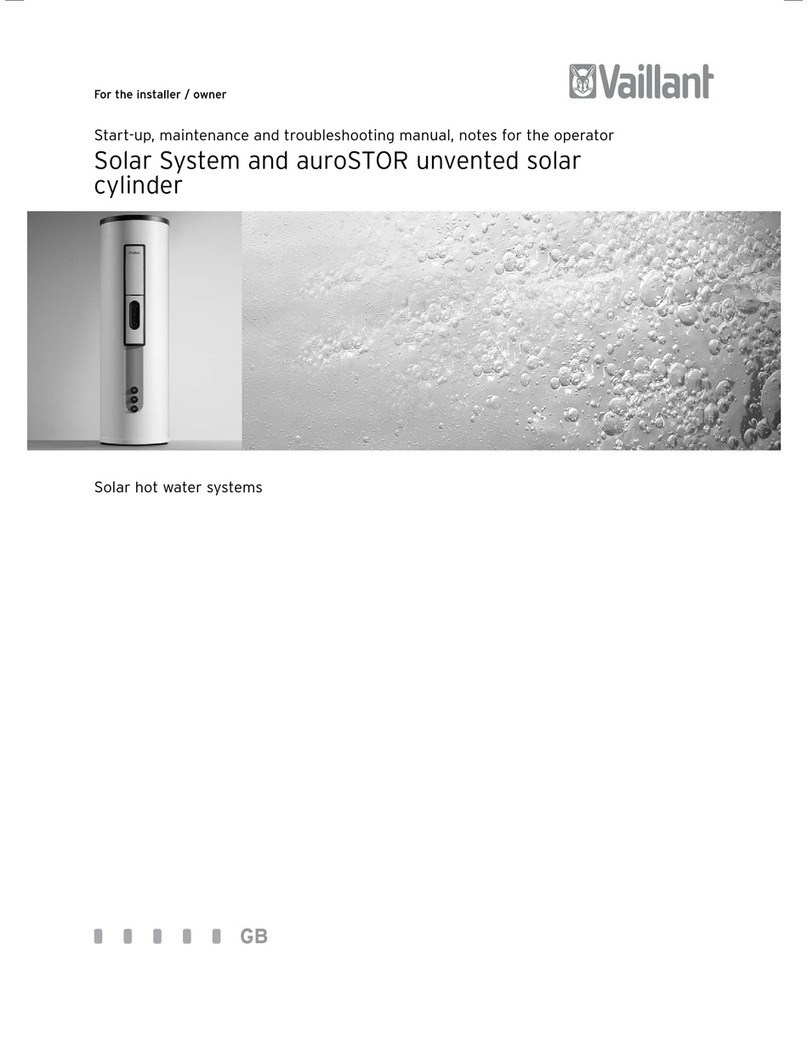
Vaillant Solar System and auroSTOR unvented solar... Programming manual

For the installer / owner
Start-up, maintenance and troubleshooting manual, notes for the operator
Solar System and auroSTOR unvented solar
cylinder
Solar hot water systems
GB

Contents
Manual - Solar hot water systems 0020009607_022
Contents
1 Notes on the documentation.............................. 3
1.1 Storage of documents..................................................3
2 Overview of standards, safety instructions..... 3
2.1 Overview of EU standards...........................................3
2.2 Regulations in Great Britain ...................................... 4
2.2.1 Technical Guidance ...................................................... 4
2.2.2 Related documents...................................................... 4
2.2.3 Regulations for the prevention of accidents......... 4
2.3 Safety instructions........................................................5
3 System description.............................................. 6
3.1 Intended use...................................................................6
3.2 Design and function of the solar system ................6
4 Description of the components..........................8
4.1 Collectors ....................................................................... 8
4.1.1 auroTHERM exclusive tube collector ...................... 8
4.1.2 VFK flat collector ........................................................ 12
4.1.3 Disposal ......................................................................... 13
4.2 Solar pump unit........................................................... 13
4.2.1 Design ............................................................................ 13
4.2.2 Water control pack...................................................... 13
4.2.3 Solar expansion vessel............................................... 13
4.2.4 Protection vessel......................................................... 13
4.3 Solar pump.................................................................... 14
4.4 Thermal cut out of the solar pump ........................ 14
4.5 Flow rate meter ........................................................... 14
4.6 Solar fluid...................................................................... 14
4.6.1 Properties of the solar fluid ..................................... 14
4.6.2 Protection of the solar circuit against frost
and corrosion ............................................................... 15
4.6.3 Frost protection of the bivalent solar cylinder .... 15
4.6.4 Safety data sheet........................................................ 16
4.7 auroSTOR solar cylinder............................................ 18
4.8 Solar control................................................................. 18
5 Installation...........................................................19
5.1 Installation of the solar cylinder .............................27
5.1.1 Description of the solar cylinder.............................27
5.1.2 Technical data of the auroSTOR solar cylinder .. 29
5.1.3 Intended use................................................................. 31
5.1.4 Data badge.................................................................... 31
5.1.5 Safety devices.............................................................. 31
5.1.6 Safety instructions and regulations ....................... 31
5.1.7 Scope of delivery......................................................... 31
5.1.8 Requirements of the installation site..................... 31
5.1.9 Transport...................................................................... 32
5.1.10 Dimensions .................................................................. 33
5.2 Functional diagram .................................................... 34
5.3 Installation of the solar circuit piping................... 35
5.3.1 General instructions .................................................. 35
5.3.2 Material......................................................................... 35
5.3.3 Laying of the solar circuit pipes............................. 35
5.3.4 Connection of the collectors to the
solar pump unit........................................................... 35
5.3.5 Bleeding of the solar circuit .................................... 36
5.4 Installation of the reheating circuit piping .......... 36
5.5 Installation of the hot water pipework.................. 36
5.5.1 Hot water thermostatic mixing valve.................... 36
5.6 Installation of the cold water supply pipework....37
5.6.1 Mains water supply pressure....................................37
5.6.2 Cold water piping ........................................................37
5.6.3 Drain valve ................................................................... 38
5.7 Discharge pipework ................................................... 38
5.7.1 Discharge pipework ................................................... 38
5.7.2 High level termination............................................... 39
5.8 Electrical installation.................................................40
5.8.1 Immersion heater.......................................................40
5.8.2 Electrical connection to the
cylinder control device............................................... 41
5.8.3 Combination options of the
control components.................................................... 41
6 Start-up...............................................................56
6.1 Flushing and filling the solar circuit......................56
6.2 Setting the flow rate and pump.............................. 57
6.3 Programming the flow rate on the controller.....58
6.4 Filling the hot water secondary circuit.................58
6.5 Setting the hot water
thermostatic mixing valve....................................... 58
6.6 Filling the reheating circuit...................................... 59
6.7 Starting up the boiler................................................ 59
6.8 Start-up protocol........................................................60
6.9 Handing over the system to the owner................60
7 Inspection and maintenance ............................60
8 Troubleshooting..................................................62
9 Notes for the owner...........................................65
9.1 General notes..............................................................65
9.2 Operation of the solar system ................................65
9.3 Operation of the solar cylinder...............................65
9.3.1 Setting the standby temperature of the
cylinder.........................................................................65
9.3.2 Switching off the solar cylinder..............................66
9.4 Frost protection ..........................................................66
9.4.1 Frost protection of the solar system.....................66
9.4.2 Frost protection of the solar cylinder ...................66
9.5 Care ...............................................................................66
9.5.1 Care of the collectors................................................66
9.5.2 Care of the solar cylinder ........................................66
9.6 Maintenance ................................................................66
9.6.1 Maintenance of the solar system ...........................66
9.6.2 Maintenance of the solar cylinder .........................66
9.7 What should be done if ............................................ 67
10 Customer service and
manufacturer's warranty ..................................67
10.1 Vaillant service............................................................ 67
10.2 Vaillant warranty ........................................................ 67
11 Start-up protocol ...............................................68
.

3Manual - Solar hot water systems 0020009607_02
1 Notes on the documentation
Your solar system is a quality product from Vaillant.
This manual describes the entire system, all of its
components and the cylinder and provides you with
information on start-up, maintenance and trouble-
shooting. It is a supplement to the operating, installation
and assembly manuals of the individual components.
Observe the manuals for each individual system
component in conjunction with this manual.
Look after this manual and pass it on to the next owner.
hNote!
The “Start-up” and “Maintenance and
troubleshooting” chapters of this manual are
intended only for approved specialists.
Vaillant accepts no liability for any damage caused by
failure to observe this manual.
Other applicable documents
- Assembly manual of the collectors
- Operating and installation manual of the controller
- Operating and installation manual of the boiler (if
used)
- Assembly, operating and installation manuals of all
accessories used
- Warranty card
1.1 Storage of documents
Store this manual and all other applicable documents
where they are readily available.
Pass the documents on to the next owner if you move or
sell the unit.
1.2 Symbols used
Please observe the safety instructions in this manual
when operating and installing the solar system and the
auroSTOR solar cylinder.
The symbols used in the manual are explained
below:
dDanger!
Immediate risk of serious injury or death!
eDanger!
Danger of death from electric shock!
eDanger!
Risk of burns or scalding!
aCaution!
Potentially dangerous situation for the product
and environment.
hNote!
Application recommendation.
• Symbol for a required task
1.3 Validity of the manual
This manual is valid exclusively for units with the follo-
wing article numbers:
Appliance type Cylinder volume Article number
VIH S GB 200 S 200 litres 307206
VIH S GB 250 S 250 litres 307207
VIH S GB 300 S 300 litres 307208
Table 1.1 Validity of the manual
To find out the article number of your unit refer to the
identification plate.
2 Overview of standards,
safety instructions
2.1 Overview of EU standards
Solar system in general
EN ISO 9488
Thermal solar system and components, terminology
(ISO/DIS 9488; 1995)
EN 12975-1
Thermal solar systems and components; Collectors, Part
1: General requirements
EN 12975-2
Thermal solar systems and components; Collectors; Part
2: Test methods
EN 1991-2-3
Eurocode 1 – Basis of design and actions on structures,
Part 2–3: Actions on structures - Snow loads
EN 12976-1
Thermal solar systems and components;
Factory made systems - Part 1: General requirements
EN 12976-2
Thermal solar systems and components;
Factory made systems - Part 2: Testing methods
ENV 12977-1
Thermal solar systems and components;
Custom built systems,
Part 1: General requirements
Notes on the documentation 1
Overview of standards, safety instructions 2

Manual - Solar hot water systems 0020009607_024
ENV 12977-2
Thermal solar systems and components;
Factory made systems,
Part 2: Testing methods
ISO 9459-1: 1993
Solar heating – Domestic water heating systems – Part 1:
Performance rating procedure using indoor test
methods
ISO/TR 10217
Solar energy – Water heating systems – Guide to
material selection with regard to internal corrosion
Collectors and collector assembly
EN 1991-2-4
Eurocode 1 – Basis of design and actions on structures -
Part 2–4: Actions on structures - Wind actions
Solar cylinder and cylinder installation
Pressure equipment directive 97/23/EC
Directive of the European Parliament and Council from
29th May, 1997 for the approximation of the laws on
pressure equipment of the Member States
EN 12977-3
Thermal solar systems and components;
Custom built systems,
Part 3: Performance characterisation of stores for solar
heating systems
EN 12897
Water supply - specification for indirectly heated
unvented (closed) storage water heaters
EN 806-1
Specifications for installations inside buildings conveying
water for human consumption - Part 1: General
EN 1717
Protection against pollution of potable water
installations and general requirements of devices to
prevent pollution by backflow
EN 60335-2-21
Safety of household and similar electrical appliances;
Part 2: Particular requirements for storage water
heaters (hot water cylinders and hot water boilers)
(IEC 335-2-21: 1989 and supplements 1; 1990 and 2; 1990,
modified)
Lightning protection
ENV 61024-1
Protection of structures against lightning – Part 1:
General principles (IEC 1024-1: 1990; modified)
BS 6651 Code of practice for protection of structures
against lightning
2.2 Regulations in Great Britain
2.2.1 Technical Guidance
The system must be installed in accordance with all rele-
vant and applicable national regulations, and must be in-
stalled to suit site conditions.
Observe all national regulations, including:
- Working at Heights Regulations 2005
- Health and Safety at Work Act 1974
- Electricity at Work Regulations 1989
- IEE Wiring Regulations BS 7671
- Lightning protection requirements
- Equipotential bonding of electrical installations.
2.2.2 Related documents
The installation of the solar system must be in accor-
dance with the relevant requirements of Health and
Safety Document No. 635 (The Electricity at Work Regu-
lations 1989), BS7671 (IEE Wiring Regulations) and the
Water Supply (Water Fitting) Regulations 1999, or The
Water Bylaws 2000 (Scotland). It should also be in ac-
cordance with the relevant requirements of the Local
Authority, Building Regulations, The Building Regulations
(Scotland), The Building Regulations (Northern Ireland)
and the relevant recommendations of the following Bri-
tish Standards:
BS EN 806: Specification for installations inside buil-
dings conveying water for human consumption
BS 6700: Services supplying water for domestic use
within buildings and their curtilages.
BS. 5449 Forced circulation hot water central heating
systems for domestic premises. Note: only up to 45 kW.
BS. 6880 Low temperature hot water heating systems of
output greater than 45 kW.
Part 1 Fundamental and design considerations.
Part 2 Selection of equipment.
Part 3 Installation, commissioning and maintenance.
BS 6114: Expansion vessels using an internal diaphragm
for unvented hot water supply systems
BS. 4814 Specification for: Expansion vessels using an
internal diaphragm, for sealed hot water heating sys-
tems.
Unvented hot water systems must comply with building
regulation G section 3.
2.2.3 Regulations for the prevention of accidents
When carrying out works such as solar installation work
it is necessary to do so in a safe and workman like man-
ner, taking due care of any aspects of the works that
could result in injuries to person in or about the building
2 Overview of standards, safety instructions

5Manual - Solar hot water systems 0020009607_02
as well as workers, passers by and the general public at
large. To that end these works must conform, but not be
limited to, the current regulations in force such as the
following
Health and Safety at Work act 1974
Work at Height Regulations 2005.
Electricity at Work Regulations 1989
All necessary Building Regulations.
Work should be preceded by a risk assessment covering
all aspects of health and safety risks, or training require-
ments that can reasonably be foreseen to be
associated with the work. All scaffolding in the UK, other
than prefabricated (zip-up) scaffold towers, must be de-
signed and constructed by a vetted contractor, and
have suitable kick boards, hand rails and where approp-
riate netting. Areas around the scaffolding should be
zoned off and marked with suitable warning signs to a
suitable distance to protect persons from falling objects.
Workers should have available and use personal protecti-
ve equipment as necessary. This would include equip-
ment such as fall protection systems, safety gloves,
goggles, dust masks as well as any specialised equip-
ment that may be in use such as lifting and handling
equipment.
The completed works shall comply with all necessary BS
EN Standards and Codes of practice as well as Building
control or planning requirements and be confirmed
where necessary by notification to building control or
the appropriate competence based notification body.
2.3 Safety instructions
The entire solar system must always be installed and
operated in accordance with recognised technical
standards.
dDanger!
Risk of falling!
Make sure you adhere to the valid work protec-
tion regulations, in particular when working on
the roof. Make absolutely sure you wear anti-fall
devices whenever there is a risk of falling. (We
recommend Vaillant fall protection systems,
item no. 302 066.) Observe the accident pre-
vention regulations of the trade associations.
HDanger!
Risk of being burned or scalded by hot
components! Install and replace collectors or
collector parts on very cloudy days. Perform
installation work on sunny days only in the
morning or evening or with the collector
covered.
dDanger!
Risk of being burned or scalded by hot solar
fluid or components! Fill and flush the solar
system when the collectors are cold. Cover the
collectors while doing so.
Danger!
Risk of being burned or scalded by escaping hot
steam!
Steam can escape from the expansion relief
valve of the solar pump unit if the system is
shut down. To avoid injuries, you must connect
the expansion relief valve to a collecting
container with a hose line.
Danger!
Risk of being scalded by hot water! With the
Vaillant auroSTOR combi cylinder, the outlet
temperatures at the taps can be up to 85 °C. To
provide effective protection against scalding in
the event of secondary return, integrate a hot
water thermostat mixer in the system (refer
to Section 5.5.1).
Danger!
Risk of being burned or scalded by escaping hot
steam! Steam can escape from unblocked
automatic bleeders if the system is shut down.
After bleeding, you should therefore always
shut off automatic bleeders or install them in a
location where vapour cannot escape.
Use the automatic Vaillant air separator system (item
no. 302 418). It works fully automatically and does not
need to be subsequently blocked. It must be installed in
an area however, in which no steam can enter, preferably
in the return pipe nearby the solar cylinder.
eDanger!
Danger of death by electric shock!
All live parts of the system may be installed,
serviced and repaired only by a qualified
servicing company!
Danger!
Risk of overvoltage!
Earth the solar circuit as potential equalisation
and protection against overvoltage! Attach
earthing pipe clips to the solar circuit pipes and
connect the clips to a potential rail with a
16 mm2copper cable.
Overview of standards, safety instructions 2
System description 3
Danger!
Risk of being scalded by hot water!
With the Vaillant auroSTOR cylinder, the outlet
temperatures could be up to 75 °C. To provide effective
protection against scalding, integrate a hot water
thermostatic mixer in the system. Vaillant supply a
suitable valve with all of our solar sets.
For air removal from the solar system pipe work use the Vaillant
automatic air separator system (item no. 302 418).
It works fully automatically and does not need to be subsequently
capped off. It must however be installed in the pipe work where no
steam can occur, preferably in the return pipe nearby the solar
cylinder.

Manual - Solar hot water systems 0020009607_026
3 System description
3.1 Intended use
The Valliant solar system has been constructed using
state-of-the-art technology in accordance with recognis-
ed safety regulations.
However, if the system is not used correctly, or as inten-
ded, this could physically endanger or result in the death
of the user or third parties, or damage the unit and
other property.
These components of the Vaillant solar system are not
intended to be used by persons (including children) with
limited physical, sensory or mental capabilities or insuffi-
cient experience and/or knowledge, unless they are su-
pervised by a person who is responsible for their safety
or have been instructed by this person on how to use
the unit.
Children must be supervised to ensure they do not play
with the unit.
The purpose of the Vaillant solar system is to provide a
solar-supported hot water supply.
Any other use or extended use is considered to be im-
proper. The manufacturer/supplier is not liable for any
resulting damage. The user alone bears the risk.
Intended use also includes observance of the operating
and installation instructions as well as all other applica-
ble documents, and also compliance with the inspection
and maintenance requirements.
aCaution!
Improper use of any kind is prohibited!
You will find a start-up report at the end of this manual.
This should be filled in by the installer and/or start-up
engineer and handed over to the operator.
All CORGI-approved installers have a CORGI ID card and
a registration number. Both of them should be entered
on the start-up checklist. You can check the details of
your installer at CORGI under the telephone number
+49 (0)1256 372300.
3.2 Design and function of the solar system
The solar system consists of four main components:
– The collectors, which absorb the solar radiation and
utilise it (refer to Section 4.1, Collectors).
– The solar control, which monitors, displays and
controls all functions of the system (refer to Section
4.8, Solar control).
– The solar pump unit, which transports the solar heat
(refer to Section 4.2, Solar pump unit).
– The solar cylinder (refer to Section 5.1, Installation of
the solar cylinder).
On days on which the solar radiation is insufficient to
heat the drinking water in the cylinder, the stored water
must be reheated by a heating system. This can be done
with boilers or electrically with an immersion heater.
3 System description

7Manual - Solar hot water systems 0020009607_02
6
7
9
2
CD
4
11
3
10
1
BA
5
12
M
WW
M
8
Fig. 3.1 System for solar heating of drinking water
Key
1 Boiler
2 auroSTOR solar cylinder
3 230 V∼motorised 2 port valve (supplied together with the solar
cylinder)
4 Immersion heater
5 230 V∼ motorised 2 port valve
6 auroTHERM collector
7 Solar pump unit
8 Protection vessel
9 Solar expansion vessel
10 Automatic air separator system
11 Drinking water expansion vessel
12 Thermostat mixing valve
A Boiler flow
B Boiler return
C Solar circuit flow
D Solar circuit return
System description 3

Manual - Solar hot water systems 0020009607_028
The Vaillant auroTHERM exclusive VTK 570 tube
collector, or auroTHERM VFK 900 and VFK 990/1 (6) flat
collector, transforms solar energy into heat and
transfers this thermal energy to a frost-protected solar
fluid. The solar pump of the solar pump unit (7) ensures
the heat is transported from the collector to the bivalent
solar cylinder (2) via a pipe system. The solar pump unit
is controlled by the solar control.
The solar control switches the solar pump on or off as
soon as the difference in temperature between the
collector and solar cylinder falls below or exceeds the
preset value. If the solar energy is insufficient, the
control system switches on the boiler (1) so that the
upper third of the cylinder is reheated to the set value
for the hot drinking water temperature. In addition the
solar cylinder can be reheated by the immersion heater
installed by the manufacturer.
The solar expansion vessel (9) compensates pressure
fluctuations in the solar circuit.
The in-line vessel (8) protects the expansion vessel from
increased temperatures in the solar circuit. We
recommend installing a protection vessel.
The Vaillant solar system enables various system
configurations and control concepts:
Electrical wiring
The Vaillant Control Center VR 65 can be used to wire
up the system if an eBUS-capable Vaillant boiler is used.
A standard wiring box can be used if a Vaillant boiler
which is not eBUS-capable or an external boiler is used.
Control of the hot water temperature
The hot water temperature in the upper third of the
cylinder can be controlled by the VRS 560 or by a
separate hot water programmer.
dDanger!
Risk of being scalded by hot water to provide
effective protection against scalding, install a
thermostat mixer in the hot water pipe as
described in Section 5.5, Installation of the hot
drinking water pipework. Set the thermostat
mixer to below 60 °C and check the
temperature at a hot water tap.
Heating control
The heating can be regulated by means of a
programmable Vaillant VRT room thermostat or VRC
weather compensator if an eBUS-capable Vaillant boiler
is used.
The Vaillant VRT 30 room thermostat or a standard
room thermostat can be used if a non-eBUS Vaillant
boiler or an external boiler is used.
The solar system is a closed system and must be bled
carefully. We recommend the automatic Vaillant air
separator system for this purpose (item no. 302 418). It
works fully automatically and does not need to be
subsequently blocked.
The automatic air separator system must be installed in
an area in which no steam can enter, preferably in the
return pipe between the solar pump unit and the solar
cylinder.
4 Description of the components
4.1 Collectors
HDanger!
Danger of burning!
To avoid injuries due to hot parts of the collec-
tors, all work on the collectors should be carried
out on cloudy days. Alternatively, work can be
carried out in the morning or evening of sunny
days or with the collector covered..
4.1.1 auroTHERM exclusive tube collector
The VTK 570 tube collector has six tubes that are con-
nected hydraulically in parallel (Fig. 4.1).
The CPC mirror increases the solar yield by reflecting
the solar energy and focussing it on the tubes.
Fig. 4.1 auroTHERM exclusive VTK 570 tube collector
3 System description
4 Description of the components

9Manual - Solar hot water systems 0020009607_02
1
2
3
4
5
7
8
9
4
10
6
Fig. 4.2 Section through auroTHERM exclusive VTK 570 sho-
wing direction of flow
Key
1 Thermal insulation
2 Receiving tank
3 Supply or return connection
4 Temperature sensor pocket
5 Vacuum tubes
6 Thermal baffle plate
7 CPC mirror
8 U-tube
9 Supply or return connection
10 Energy collector tube or distributor pipe
Description of the components 4

Manual - Solar hot water systems 0020009607_0210
Technical data, tube collectors
Appliance designation Units auroTHERM exclusive VTK 570
Surface area (gross, aperture/net) m21,28 / 0,82
Height mm 1695
Width mm 790
Depth mm 100
Weight kg 20
Collector capacity l 3,56
Copper pipe connection, flat-face Thread 3/4“
Insulation: high-vacuum bar 10-6
Max. operating pressure bar 6
Spiegel Reinsilber, Reflexionsgrad ρ% 94 ±1
Absorber emission ε% 5 ±2
Absorber absorption α% 95 ±1,0
Solar sensor sleeve ∅mm 6
CE label 0036
Shutdown temperature (according to prEN 12975-2,
c < 1 m/s) in the glass tube °C 250
Shutdown temperature (according to prEN 12975-2,
c < 1 m/s) at the collector connection °C 180
Efficiency η0(according to 12975) % 78 ± 3%
Efficiency coefficient k1W/(m2•K) 1,09 ±0,2
Efficiency coefficient k2W/(m2•K2) 0,01 ±0,002
Table 4.1 Technical data, auroTHERM exclusive tube collectors
0
0%
10%
20%
30%
40%
50%
60%
70%
80%
5101520253035404550556065707580
ΔT = TCollector - TAmbient air [K]
Efficiency η
Fig. 4.3 Efficiency of auroTHERM collector with radiation ener-
gy content of 300 W/m2
4 Description of the components

11Manual - Solar hot water systems 0020009607_02
10%
0%
20%
30%
40%
50%
60%
70%
80%
5101520253035404550556065707580
ΔT = TCollector - TAmbient air [K]
Efficiency η
Fig. 4.4 Efficiency of auroTHERM collector with radiation ener-
gy content of 800 W/m2
Pressure loss [mbar]
Flow rate [l/min]
VTK 1140
VTK 570
0
0
20
40
60
80
100
120
0,25 0,5 0,75 1 1,25 1,5 1,75 2 2,25 2,5 2,75 3 3,25 3,5 3,75 4 4,25 4,5 4,75 5
Fig. 4.5 Pressure loss of the auroTHERM exclusive collector
Description of the components 4

13Manual - Solar hot water systems 0020009607_02
4.1.3 Disposal
All Vaillant solar collectors meet the requirements for
the German “Blauer Engel” (Blue Angel) environmental
mark.
Therefore, we, as the manufacturer, will take back and
recycle components when they have to be disposed of
after years of reliable use.
4.2 Solar pump unit
1
2
9
8
11
10
7
6
5
4
3
Fig. 4.9 Design of the solar pump unit
Key
1 Expansion relief valve
2 Pressure gauge
3 Pressure release pipe with collecting container
4 Solar expansion vessel
5 Protection vessel (optional)
6 Fill/vent valve (for filling and draining the solar circuit)
7 Flow rate meter
8 Three-speed solar pump
9 Fill/vent valve (for filling the solar circuit)
10 Group of pipes with insulation
11 Stop valves with gravity brakes
4.2.1 Design
The solar pump unit transports heat from the collector
to the consumer safely and efficiently.
The solar pump unit mainly consists of:
- The group of pipes of the solar pump unit with
insulation (10)
- Two stop valves with gravity brakes (11) to prevent
heat diversion. (The gravity brakes are ineffective if
the stop valves are in the 45° position.)
- The water control pack with an expansion relief valve
(1) with 6 bar blow-off pressure and a pressure gauge
(2) for visual inspection
- Two fill/vent valves for filling and draining the solar
circuit (6and 9)
- A three-speed solar pump (8)
- A flow rate meter to optimally adjust the required flow
rate (7)
- A solar expansion vessel (4) (separate accessory)
- A protection vessel (5) (separate accessory)
4.2.2 Water control pack
The solar pump unit is delivered with a water control
pack, consisting of an expansion relief valve (1) and a
pressure gauge (2) for visual inspections.
4.2.3 Solar expansion vessel
The solar expansion vessel (4), is used to equalise the
pressure while the pressure relief valve (1) blows off the
solar fluid into the collecting container via the pressure
release pipe (3) if the operating pressure of 6 bar is
exceeded.
hNote!
The solar fluid container is of sufficient size
and intended as a collecting container. Establish
a permanently integrated blow-off line between
the expansion relief valve and collection tank.
The size of the solar expansion vessel is based on the
collector volume and the expansion volume of the solar
system.
The expansion vessel not only accommodates the
expansion volume of the solar fluid, but also the entire
volume of the collectors in the event of a shutdown. The
total volume of the solar system is the total of the
individual values of the collector, heat exchanger volume
and the volume of the pipeline.
The admission pressure of the solar expansion vessel
can be set between 0.5 and 4.0 bar.
4.2.4 Protection vessel
In the event of unfavourable system configurations (e. g.
very large collector surface, installation of the solar
pump unit under roof), the solar expansion vessel (4)
may be subjected to excessive temperatures by the solar
fluid if the system is shut down. In worst cases, this can
cause the membrane of the solar expansion vessel to be
overheated and to fail.
The installation of a protection vessel (5) is recommen-
ded in all cases. The solar expansion vessel is protected
from excessive temperatures by 5 l, 12 l or 18 l of solar
fluid in front of it. Vaillant recommends the installation
of a protection vessel for all solar systems (item no.
302405).
Description of the components 4
- .
.
Key
1 Expansion relief valve
2 Pressure gauge
3 Pressure release pipe with collecting container
4 Combined Solar expansion/protection vessel will be supplied
with Vaillant pre defined sets.
5 Protection vessel NOT required when above vessel supplied
and fitted(optional for bespoke systems)
6 Fill/vent valve (for filling and draining the solar circuit)
7 Flow rate meter
8 Three-speed solar pump
9 Fill/vent valve (for filling the solar circuit)
10 Group of pipes with insulation
11 Stop valves with gravity brakes
The installation of solar protection for the expansion vessel (5 see
Fig 4.9 key) is recommended in all cases. In the case of Vaillant
solar sets a combined expansion and protection vessel is supplied.
This incorporates both requirements into one easy fit device.
For bespoke systems the solar expansion vessel is protected
from excessive temperatures by 5 l, 12 l or 18 l of solar
fluid in front of it. Vaillant recommends the installation
of a protection vessel for all solar systems.

Manual - Solar hot water systems 0020009607_0214
4.3 Solar pump
The solar pump unit is equipped with a three-speed solar
pump (Fig. 4.9, pos. 8) for the optimum adaptation of
the required circulating volume and the pump capacity
in the solar circuit.
Select the pump capacity, depending on the solar system
(e. g. collector surface, pipe diameter, length of the solar
circuit), so that the actual flow rate is slightly higher
than the nominal flow rate. The flow rate meter (Fig. 4.9,
pos. 7) is used for fine adjustment of the flow rate.
Observe the notes in Section 6.2, Setting the flow rate
and pump.
4.4 Thermal cut out of the solar pump
In order to comply with the requirements for unvented
hot water storage systems (G3) the power supply to the
solar pumps(s) must be taken via a manually resetable
temperature cut off on the hot water cylinder.
The Vaillant auroSTOR cylinder has such as device facto-
ry fitted, and this is wired in series with the power supp-
ly to the solar pump.
hNote
If an East - West system is being installed then
the installation of a relay (to allow independant
operation of each pump) may be necessary.
1
3
A
B
C
D
A
B
C
D
3
3
Fig. 4.10 Connection diagram of the solar pump TCO
The solar pump is secured by its own thermal cut out
(TCO) (1) which is mounted on the solar cylinder (pre-
assembled at the factory for the VIH S GB 250 and
300 S). The power supply to the pump is interrupted at
cylinder temperatures higher than 90 °C.
4.5 Flow rate meter
0,5
1
2
3
0,5
1
2
3
4
5
6
4
5
6
L/min
L/min
1,1 l/min
1
2
Fig. 4.11 Flow rate meter 0 - 6 l/min
The flow rate meter (pos. 7, Fig. 4.6) installed in the
return pipe is an essential component of the solar
system. To achieve optimum heat transfer, you must
achieve a certain flow rate, which is referred to as the
nominal flow rate (refer to Section 6.2, Setting the flow
rate and pump).
Upper deviations are not as serious as lower deviations.
Make the rough adjustments with the solar pump first.
You can make the fine adjustments with the adjustment
valve (1) of the flow rate meter. You can view the set
value on the display (2) of the flow rate meter.
The flow rate meter has a fill/vent valve for filling and
draining the solar circuit.
h
Note
Do not under any circumstances set the flow
rate below the calculated flow rate. The
collector efficiency will be considerably reduced.
4.6 Solar fluid
4.6.1 Properties of the solar fluid
This information applies to Vaillant solar fluid (20 l
canister: item no. 302 429).
Vaillant solar fluid is a ready-mixed antifreeze and
anticorrosive, consisting of approximately 45%
propylene glycol with anti-corrosion inhibitors and 55%
water. It is resistant to high temperatures and can be
used both with Vaillant tube collectors and Vaillant flat
plate collectors.
Furthermore the solar fluid has a high thermal capacity.
The inhibitors provide reliable corrosion prevention
when using different types of metal (mixed installations).
4 Description of the components

15Manual - Solar hot water systems 0020009607_02
h
Note!
Do not use any other anti-freeze or inhibitors
with Vaillant solar collectors.
Only Vaillant solar fluid is approved.
a
Caution!
Risk of damage!
Vaillant solar fluid is ready mixed. You may not
under any circumstances mix it with water or
other fluids. Otherwise it will become
ineffective as an antifreeze or anticorrosive,
resulting in damage to collectors or other parts
of the system.
Vaillant solar fluid is infinitely durable in hermetically
sealed containers.
Skin contact is normally not dangerous. Eye contact only
causes minor irritations, you should nevertheless
immediately wash your eyes.
Observe the safety data sheet (refer to Section 4.6.4).
4.6.2 Protection of the solar circuit against frost
and corrosion
To protect the solar system reliably against frost in
winter, the entire solar circuit must be filled 100 % with
solar fluid (item no. 302429).
h
Note!
You can achieve frost resistance of about
-28 °C by filling the solar system with Vaillant
solar fluid.
No damage is caused by frost even at outside
temperatures below -28 °C, since the expansive
effect of the water is reduced. Check the
antifreeze effect after filling the system and
then once a year.
Component Volume (l)
VIH S GB 200 S heat exchanger solar circuit 4.12
VIH S GB 250 S heat exchanger solar circuit 4.12
VIH S GB 300 S heat exchanger solar circuit 4.4
VIH S GB 200 S heat exchanger reheating circuit 3.7
VIH S GB 250 S heat exchanger reheating circuit 3.7
VIH S GB 300 S heat exchanger reheating circuit 3.7
Solar pump unit 0.9
auroTHERM exclusive VTK 570 0,8
auroTHERM VFK 900 1,1
auroTHERM classic VFK 990/1 1,1
Protection vessel 5, 12 or 18 l
Table 4.3 Volume of the individual components
Pipe diameter Pipeline volume (l/m)
15 mm 0.18
18 mm 0.20
22 mm 0.31
28 mm 0.50
flexible pipe DN 12 mm 0.15
flexible pipe DN 16 mm 0.27
flexible pipe DN 20 mm 0.36
Table 4.4 Pipeline volume
Proceed as follows to check the solar fluid; refer to the
operating manual of the solar fluid tester
(item no. 0020020155):
• Suck in the amount of fluid for the float to freely float
without sticking at the top with the suction ball of the
solar fluid tester (item no. 0020020645).
• View the density on the scale. The density must be
greater than 1.05 g/cm3. You must otherwise replace
the solar fluid.
• Measure the pH value with a pH value measuring strip.
You must replace the solar fluid if the pH value is
below 7.5.
1
2
3
4
5
6
Fig. 4.12 Solar fluid tester
Key
1 Transport case
2 Areometer
3 Thermometer
4 pH indicator rod
5 Standing cylinder
6 Operating manual
a
Caution!
Risk of damage!
Use only the original Vaillant solar fluid tester
(item no. 0020020645). Otherwise an
incorrect antifreeze value may be indicated.
4.6.3 Frost protection of the bivalent solar cylinder
You must drain the solar cylinder completely if it is to be
shut down in a room prone to frost. It is drained at the
cold water inlet with a T-piece with tap to be provided by
the installer.
Description of the components 4

Manual - Solar hot water systems 0020009607_0216
• Also drain all heat exchangers which are not filled with
solar fluid.
4.6.4 Safety data sheet
1. Substance/Formulation and company name
1.1 Information on the product:
Trade name of the Vaillant solar fluid
(item no. 302 362)
1.2 Information on the supplier:
Vaillant GmbH, Berghauser Str. 40,
42859 Remscheid, Germany
Telephone +49 (02191) 18 - 0,
fax +49 (02191) 182810,
Emergency information: your local poison
information centre
(see directory assistance or telephone directory).
2. Composition/Information on components
2.1 Chemical properties
Watery solution of 1.2 propylene glycol with
corrosion inhibitors
3. Possible risks
3.1 No particular risks known
4. First-aid measures
4.1 General notes:
Remove dirty clothes.
4.2 After inhaling:
Discomfort after inhaling fumes/
aerosol: fresh air, help from a doctor.
4.3 After skin contact:
Wash off with water and soap.
4.4 After eye contact:
Wash thoroughly under running water with wide
open eyes for at least 15 minutes.
4.5 After swallowing:
Rinse your mouth and then drink plenty of water.
4.6 Notes for the doctor:
Treatment of symptoms (decontamination,
vital function), no specific antidote known.
5. Firefighting measures
5.1 Appropriate extinguishing agents:
Spray, solid extinguishing agent, alcohol-fast
foam, carbon dioxide (CO2)
5.2 Particular hazards:
Fumes which are detrimental to health. Formation
of smoke/mist. The specified substances/
substance groups may be released in the event of
a fire.
5.3 Special protective equipment for fire fighting:
Wear a breathing apparatus which is independent
of the circulating air in the event of a fire.
5.4 Further details:
The hazard depends on the combustible
substances and the fire conditions. Polluted fire
water must be disposed of according to local
official regulations.
6. Measures to be taken if substances are
released accidentally
6.1 Individual-related measures:
No particular measures required.
6.2 Environmental measures:
The product may not be discharged into waters
without pre-treatment (biological sewage plant).
6.3 Cleaning/Collection methods:
Pump out the product in the event of large
quantities.
Absorb small quantities with appropriate fluid
bonding material. Then dispose of them according
to regulations.
Rinse away splashes with plenty of water. Inform
the local water authority in the event of large
quantities which could flow into the drainage or
waters.
7. Handling and storage
7.1 Handling:
Good ventilation of the workplace, no other
particular measures required.
7.2 Fire and explosion protection:
No exceptional measures required.
Cool any endangered containers with water.
7.3 Storage:
Close containers tightly and store them at dry
places. Do not use any galvanised containers for
storage.
8. Limitation of exposure and personal protective
equipment
8.1 Personal protective gear:
Hand protection: chemical-resistant protective
gloves (EN 374). Suitable materials even in the
event of prolonged, direct contact (recommended:
protection index 6, corresponding to > 480
minutes permeation time according to EN 374):
flour elastomer (FKM) – 0.7 mm layer thickness.
Suitable materials for brief contact or splashes
(recommended: at least protection index 2,
corresponding to > 30 minutes permeation time
according to EN 374): nitrile rubber (NBR) – 0.4
mm layer thickness. Due to the large variety of
types, observe the instruction manuals of the
manufacturer.
8.2 Eye protection:
Safety glasses with lateral protection (framed
glasses) (EN 166)
8.3 General safety and hygiene measures:
Observe the usual protective measures for
dealing with chemicals.
4 Description of the components

17Manual - Solar hot water systems 0020009607_02
9. Physical and chemical properties
Form: fluid
Colour: violet
Odour: product-specific
Solidification temperature: approx. -28 °C
(DIN 51583)
Boiling temperature: > 100 °C (ASTM D 1120)
Flash point: none
Lower explosion limit: 2.6 % by vol. (details for
Upper explosion limit: 12.6 % by vol. 1.2 propylene
glycol)
Ignition temperature: omitted
vapour pressure (20 °C): 20 mbar
Density (20 °C): approx. 1.030 g/cm3 (DIN 51757)
Water solubility: entirely soluble
Solubility (qualitative) solvent: polar solvents:
soluble
pH value (20 °C): 9.0 – 10.5 (ASTM D 1287)
Viscosity, kinematic (20 °C): approx. 5.0 mm2/s
(DIN 51562)
10. Stability and reactivity
10.1 Substances to be avoided: Strong oxidants
10.2 Dangerous reactions:
No dangerous reactions if the storage and
handling regulations/notes are observed
10.3 Dangerous decomposition products:
No dangerous decomposition products if the
storage and handling regulations/notes are
observed.
11. Toxicological information
11.1 Acute toxicity:
LD50/oral/rat: > 2000 mg/kg
Primary skin irritation/rabbit: not irritating.
(OECD guideline 404)
Primary irritation to the mucous membrane/
rabbit: not irritating.
(OECD guideline 405)
11.2 Additional notes:
The product has not been checked. The
statements have been taken from the individual
components.
12. Ecological information
12.1 Ecological toxicity:
Fish toxicity: LC50 leuciscus idus (96 h):
> 100 mg/l
Aquatic invertebrates: EC50 (48 h): > 100 mg/l
Water plants: EC50 (72 h): > 100 mg/l
Micro-organisms/effect on activated sludge:
DEV-L2 > 1000 mg/l. No disturbances to the
biodegrading activity of the activated sludge are
expected in adapted biological sewage plants if
discharged appropriately in low concentrations.
12.2 Assessment of aquamatic toxicity:
The product has not been checked. The
statements have been taken from the properties
of the individual components.
12.3 Persistence and biodegradability/information on
elimination:
OECD 301 A test method (new version)
Analysis method: DOC acceptance
Degree of elimination > 70 % (28 d)
Assessment: easily biodegradable.
13. Note on disposal
13.1 Disposal:
Vaillant solar fluid (item no. 302 363) must de
disposed of at an appropriate waste site or waste
incineration plant, for example, while observing
local regulations. Contact the local municipal
sanitation office or the mobile environmental
service for quantities under 100 l.
13.2 Uncleaned packings:
Uncontaminated packings can be reused. Dispose
of packings which are unable to be cleaned
together with the substance.
14. Transport information:
VbF: not subject to the ordinance on combustible
fluids.
Mailing permitted. GGVE/RID: -, UN no.: -,
GGVS/ADR: -, IATA DGR: -, IMDG code: -, TA air: -.
No dangerous goods according to transport
regulations.
15. Regulations
15.1 Labelling in accordance with EC directives/
national regulations:<NewLine/>No labelling
obligation
15.2 Other regulations: water hazard class (Germany,
Appendix 4 of the VwVwS (administrative
regulation on water-pollutant substances) from
17.05.1999): (1), slightly water-pollutant
16. Other information
The safety data sheet is intended to provide
essential physical, safety-related, toxicological and
ecological data and give recommendations for
safe handling or safe storage, handling and safe
transport of chemical substances and
formulations. No liability is assumed for damage
in connection with the usage of this information
or the usage, application, adaptation or
processing of the products described here. This
does not apply as long as we, our statutory
agents or assistants are liable in the event of
intention or gross negligence. No liability is
assumed for indirect damage.
This information has been compiled to the best of
our knowledge and conscience according to our
current state of knowledge.
No guarantee can be made for product properties.
17. Version
Compiled by Vaillant GmbH on 1/7/2003
Description of the components 4

Manual - Solar hot water systems 0020009607_0218
4.7 auroSTOR solar cylinder
The auroSTOR solar cylinder is described in detail in
Section 5.1, Installation of the solar cylinder, of this
manual.
4.8 Solar control
1
230 V~
3A
C
D
B
4
2
5
Sp 1
Sp 2
Solar gain
6
Kol 1
Fig. 4.13 Temperature difference control
Key
1 Solar control
2 Boiler
3 Solar cylinder
4 Thermal cut out of the solar pump
5 Solar pump
6 Solar pump unit
Kol 1 Collector temperature sensor
Sp 1 Upper stored water temperature sensor
(reheating circuit/standby part)
Sp 2 Lower stored water temperature sensor (solar circuit)
A Boiler flow
B Boiler return
C Solar flow
D Solar return
Type of solar control
The Vaillant solar system enables various system
configurations and control concepts.
Control of the hot water temperature
The hot water temperature in the top half of the cylinder
can be controlled by the Vaillant auroMATIC VRS 560
solar control or by using a separate hot water
programmer (refer to Section 5.8, Electrical installation).
Wiring
The Vaillant Control Center VR 61 or VR 65 can be used
to wire up the system if an eBUS-capable Vaillant boiler
is used.
A standard wiring box can be used for all other boilers.
Solar pump control
Temperature differences, not absolute temperature
values, are important for the operation of solar systems.
That is why solar systems are controlled by what is
referred to as temperature difference controllers.
Temperature sensors measure the difference between
the collector and solar cylinder.
The solar pump is switched on if the difference in
temperature (Kol 1 - Sp 2) is greater than 7 K. The solar
pump of the solar system is switched off if the difference
in temperature (Kol 1 - Sp 2) is lower than 3 K.
Furthermore the solar control constantly measures the
cylinder temperature. Reheating is switched on if the
value (Sp 1) falls below the set target value.
You can set the difference in temperature on the
controller between 2 and 15 K. The default setting of 7 K
is sufficient for most solar systems.
Do not set temperature differences too low. This would
result in a number of unnecessary and uneconomic
switch-on and switch-off procedures.
auroMATIC 560 controller
Fig. 4.14 auroMATIC 560
The auroMATIC 560 solar control is a differential
temperature-controlled control set for solar-supported
hot water supply with a demand driven reheating
function for Vaillant boilers.
The control set is a fully-equipped system for solar
systems with a collector array and a solar cylinder.
It is possible to determine the solar gain by means of an
additional gain sensor (available as an accessory).
4 Description of the components

19Manual - Solar hot water systems 0020009607_02
Control Center VR 65
The Control Center VR 65 provides a system solution
which allows Vaillant low-voltage eBUS controllers to be
used in the English market with valves and hot water
cylinders with traditional 230 V cylinder thermostats.
The information on the heat requirements of the solar
cylinder is forwarded to the Vaillant ecoTEC boiler by
the Control Center VR 65. The boiler decides whether
hot water requirements has to be met and sends the
signal to control the 230 V valves via the VR 65.
In this way, the boiler can store different target
temperatures for heating and hot water operation.
Standard 230 V components can be integrated in the
Vaillant eBUS system via the Control Center VR 65. For
wiring, refer to Section 5.8, Electrical installation, and
the installation manual of the Control Center VR 65
(item no. 0020007476).
VRT 360 programmable room thermostat
The VRT 360 is a programmable room thermostat with a
week programme for heating, hot water and circulation
pump, which can be connected to Vaillant boilers with
With the VRT 360, you can preset the room temperature
with a heating programme.
The VRT 360 has additional functions including central
heating override and the time control function of an
additional circulation pump.
For wiring, refer to Section 5.8, Electrical installation,
and the operating and installation manual of the
VRT 360 (item no. 838568).
h
Note!
If the VRT 360 is used for central heating
control, the Control Center VR 65 is
additionally required to measure the solar
cylinder temperature and switch from cylinder
reheating to heating mode and vice versa as
required.
VRC 400 weather compensator
The VRC 400 weather compensator is an external
temperature compensator and can be used in
conjunction with a Vaillant eBus boiler to provide time
and temperature control of the central heating.
5 Installation
• Use the following tables to check the scope of delivery
before beginning with the installation.
Installation sequence
Install the solar system in the following order:
- Solar collectors and solar pump unit
- Solar cylinder
- Solar circuit piping
- Reheating circuit piping
- Hot water piping and secondary return (if available)
- Cold water supply
- Discharge pipe
- Electrical installation
• Assemble the collectors according to the assembly
manual (enclosed with collector installation set).
• Install the solar pump unit according to the installation
manual (enclosed with solar pump unit).
• Proceed with the installation as described in the
following sections.
Description of the components 4
Installation 5
N.B. secondary return not recommended.

Manual - Solar hot water systems 0020009607_0226
auroTHERM VFK fixing sets In-roof kit for 2 collectors In-roof kit for 3 collectors
Item no.: 0020057933 0020059990
In-roof basic kit (fixing material) 309633 309633
In-roof extra kit (metal sheets) 302389 302389
In roof extension set (for an additional collector) - 302390
Table 5.4 Scope of delivery, auroTHERM VFK fixing sets
auroSTOR solar cylinders VIH S GB 200 S VIH S GB 250 S VIH S GB 300 S
Item no.: 307206 307207 307208
Safety group with tundish 1 1 1
Motorised 2 port valve for regulation of reheating circuit
AB
1 1 1
Hot water expansion tank 18 l 1--
Hot water expansion tank 25 l -11
Wall bracket for hot water expansion tank 1 1 1
Carrier handle 1 1 1
Crimp connections 111
Drain valve 111
Safety thermostat for solar pump (bracket, cable, capillary tube) pre-assembled pre-assembled pre-assembled
Table 5.5 Scope of delivery, auroSTOR
5 Installation
.

27Manual - Solar hot water systems 0020009607_02
5.1 Installation of the solar cylinder
5.1.1 Description of the solar cylinder
20
21
22
23 19
1
2
3
N
L
immersion
heater
C°
cylinder
control
C°
1
2
45
6
13
12
14
15
16
18
17
7
8
9
10
11
3
Fig. 5.1 auroSTOR function elements
Key
1 Hot water connection
2 Temperature and pressure relief valve (95 °C, 7 bar)
3 Hot water expansion tank
4 Connection for hot water expansion tank
5 Pressure-controlled cold water outlet
6 Cold water pipe
7 Pressure limiting valve (3.5 bar) with sieve
8 Expansion relief valve (one port valve, 6.0 bar)
9 Tundish
10 Cylinder drain valve
11 Sp 2 temperature sensor immersion pocket
12 Adjustable feet
13 Return (solar circuit)
14 Supply (solar circuit)
15 Return (gas fired wall hung boiler)
16 Supply (gas fired wall hung boiler)
17 Immersion heater switch
18 Safety thermostat for solar pump, set at 90 °C, connected to
solar pump; isolates this heat source if the solar control mal-
functions
19 Safety thermostat for immersion heater
20 Cylinder thermostat (20 °C - 65 °C)
21 Immersion heater
22 Safety thermostat, set to 90 °C, connected to the motorised 2
port valve; isolates the primary heat source if the domestic hot
water thermostat fails.
23 Thermostat, immersion heater
hNote!
The safety thermostat can be removed if the
solar energy system is operated using a Vaillant
auroMATIC VRS 560 in conjunction with a
Vaillant eBUS compatible boiler.
Installation 5
This manual suits for next models
3
Table of contents
Other Vaillant Water System manuals
Popular Water System manuals by other brands

Neo-Pure
Neo-Pure RO-4300Rx-DLX Installation, operation and service manual

CLIVET
CLIVET WDAT-ik4 Manual for installation, use and maintenance

Mi-T-M
Mi-T-M WTR Series Operator's manual

Watts
Watts FMRO4G-ERP-75 Installation, operation and maintenance

Eljen
Eljen Mantis M5 Series Design & Installation Manual

Balboa
Balboa Wavezone3NE Installation Instructions and Maintenance Manual