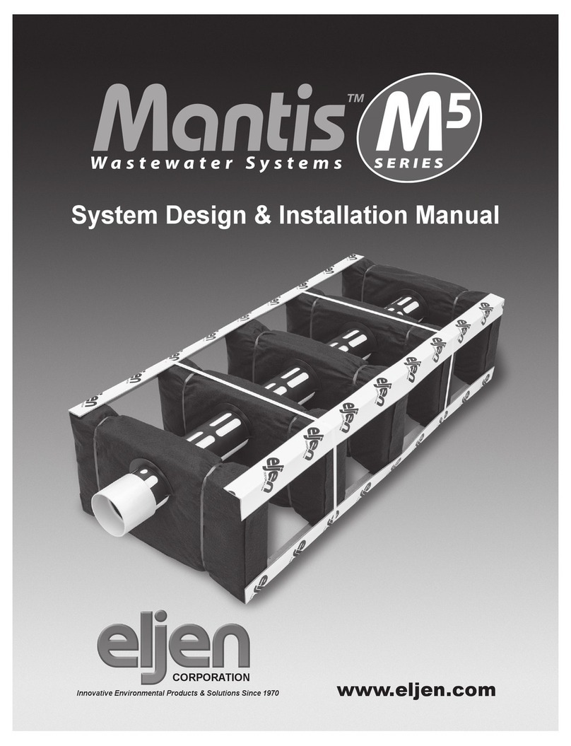
Eljen Mantis M5 Series User manual

System Design & Installation Manual
Virginia
www.eljen.com
March 2013
CORPORATION
Innovative Environmental Products & Solutions Since 1970


TOPIC Page
Glossary of Terms ............................................................ 4
Mantis M5Series General Description............................................. 5
1.0 General System Information ................................................. 9
2.0 Systems for Level Sites .....................................................10
3.0 Systems for Sloped Sites ...................................................10
4.0 Trench Installation Guidance................................................. 11
5.0 Pumped System Guidance ..................................................13
6.0 System Ventilation Guidance ................................................14
7.0 Recommended Notes on Design Plans ........................................16
TABLES
Table 1 Specied Sand Sieve Requirements........................................ 4
Table 2 Mantis M5Series GMP 116 Design Table . . . . . . . . . . . . . . . . . . . . . . . . . . . . . . . . . . . . 6
Table 3 Mantis M5Series GMP 135 Design Table .................................... 7
Table 4 Mantis M5Series GMP 127 Design Table .................................... 8
MANTIS M5SERIES DRAWINGS
Fig. 1 Mantis M5Series Components ............................................ 5
Fig. 2 Mantis M5Series Trench Cross Section .....................................10
Fig. 3 Mantis M5Series Multiple Trench Cross Section ..............................12
Fig. 4 Mantis M5Series Multiple Trench Plan View ..................................12
Fig. 5 Mantis M5 Series Pressure Distribution—Orice Layout.........................13
Fig. 6 Mantis M5 Series Venting Diagram .........................................14
Fig. 7 Mantis M5 Series 2˝ By-Pass Line for Pressurized Systems......................15
Fig. 8 Mantis M5 Series 2˝ By-Pass Line for Pump to Gravity Systems ..................15
Table of Contents
2013 Virginia Mantis M5Design & Installation Manual Page 3 www.eljen.com

Mantis M5 Series Units The Mantis M5Series units come preassembled and are 5 feet in length (as measured
from the Support Distribution Pipe) and 12” high. 12” and 24” wide models are available.
The 12” wide model is the Mantis 5.1, and the 24” wide model is the Mantis 5.2. All mod-
els have 6” of Specied Sand under and to the sides of the product. 1” of Specied Sand
is placed over the units prior to backll.
Support Distribution Pipe The Mantis M5Series Support Distribution Pipe is 5 feet in length and constructed from
crush resistant PVC Pipe. The pipes provide 3 pre-drilled one inch holes at specied
spacing located at the 12, 5 and 7 o’clock position.
Filter Support Module There are 5 Filter Support Modules for each M5unit. All Filter Support Modules are 4”
thick. The 5.1 model is 12” wide and the 5.2 model is 24” wide.
Specied Sand The Specied Sand envelope around the Mantis M5Series (6” minimum underneath, 6”
minimum on the sides, 1” minimum on the top, and 8” in-between the Support Modules)
shall meet the requirements as indicated in the Specied Sand Requirements chart listed
below. This sand is an ASTM C33 WASHED CONCRETE SAND WITH LESS THAN
10% PASSING #100 SIEVE AND LESS THAN 5% PASSING A #200 SIEVE
Ask your material supplier for a sieve analysis to verify that your material meets the re-
quired specications.
TABLE 1: Specied Sand SIEVE REQUIREMENTS
Glossary of Terms
2013 Virginia Mantis M5Design & Installation Manual Page 4 www.eljen.com
Design Flow
The estimated design ow that is used to size a Mantis system is 150 gallons
per day per Bedroom.
Eljen Mantis M5 Series
ASTM C33 Specied Sand Requirements
Sieve Size Sieve Square
Opening Size
Specication
Percent
Passing
(Wet Sieve)
0.375˝ 9.5 mm 100.0
#4 4.75 mm 95.0 – 100.0
#8 2.36 mm 80.0 – 100.0
#16 1.18 mm 50.0 – 85.0
#30 600 µm 25.0 – 60.0
#50 300 µm 5.0 – 30.0
#100 150 µm < 10.0
#200 75 µm < 5.0
Request a sieve analysis from your material supplier to ensure
that the system sand meets the specication requirements
listed above.

Note: Design layouts and installation instructions for
sequential, equal or dosed distribution systems are included.
Details on unique design and construction procedures are
also provided. To receive design standards for specially
engineered dosing systems or commercial systems, contact
Eljen’s Technical Resource Department at 1-800-444-1359.
Mantis M5Series systems must be designed and constructed
according to this Design & Installation Manual and per the
requirements of GMP 116, GMP 135, and GMP 127 where
applicable.
How the Mantis M5Series System Works
The Eljen Mantis M5Series is a wastewater disposal
technology comprised of a proprietary ltering process that
applies claried efuent to the soil. The Mantis M5Series
performance is based on accepted industry principals of
increasing the receiving soils long term acceptance rate
by keeping the biological growth off the native soils and
within the system. This technology utilizes 3 dimensional
surface areas to improve efuent quality, resulting in greater
reliability and ease of operation.
• The Support Distribution Pipe provides internal distribution,
a venting conduit for the system and secures the ve
Filter Support Modules in place. This distribution pipe is
centered within the Filter Support Module to distribute
septic efuent.
• Septic efuent is ltered through the Filter Support Modules.
Each module consists of a cuspated core surrounded by
Bio-Matt geo-textile fabric. Its unique design provides
increased surface area within each module. This area is
known as the Internal Surface Optimization envelope, ISO
for short. The ISO envelope provides an increased surface
area that greatly exceeds the Filter Support Module’s
footprint, a traditional gravel footprint or that of a graveless
replacement technology.
• Open air channels within the modules support aerobic
bacterial growth on the Filter Support Modules geotextile
fabric interface, surpassing the surface area provided by
traditional absorption systems.
• Efuent is transferred into the Specied Sand layer
which supports unsaturated ow into the native soil. This
Specied Sand and soil interface maintains soil structure
while maximizing the available absorption of the native
soil.
• The Specied Sand layer also protects the soil from
compaction and helps maintain existing pore spaces in the
soil. This preserves the soil’s natural inltration capacity
which is critical for long-term performance, especially in
ner textured soils.
Mantis M5Series General Description
2013 Virginia Mantis M5Design & Installation Manual Page 5 www.eljen.com
FIGURE 1: MANTIS M5SERIES COMPONENTS
4" SUPPORT
DISTRIBUTION PIPE
(SDP)
FILTER
SUPPORT
MODULE
(FSM)
THE SDP PROVIDES (3) PRE-DRILLED,
ONE-INCH HOLES WITHIN EACH MODULE
LOCATED AT THE 12, 5 AND 7 O'CLOCK POSITION
12"
60"
6"
MANTIS M5 UNIT
* NOTE
*NOTE: PRODUCT & INSTALL WIDTH WILL VARY DEPENDING ON MODLE USED.
SEE FIGURE 2 FOR MORE INFORMATION.
SPECIFIED SAND
*NOTE
18"

TABLE 2: MANTIS M5 SERIES GMP 116 DESIGN TABLE
NOTE: Hydraulic loading rates shown reect the maximum reduction allowed for systems per GMP 116.
1. Number of Mantis M5 Series units is determined on the current VDH loading rates dened in 12 VAC 5-610-950
2. Mantis M5Series 5.2 unit = 6 ft²/lf or 30 ft² per unit, and a minimum of 20 units
3. Mantis M5Series 5.1 unit = 4 ft²/lf or 20 ft² per unit, and a minimum of 30 units
4. The minimum Mantis M5Series system area required is 300 ft²
5. The minimum number of bedrooms for residential designs shall be 2 bedrooms
Mantis M5Series GMP 116 Design Table
2013 Virginia Mantis M5Design & Installation Manual Page 6 www.eljen.com
Soil
Texture
Percolation
Rate
(mpi)
Soil
Typ
e
5 I 0.91 165 45 930 6
10 I0.83 181 50 10 35 7
15 I0.76 198 50 10 35 7
20 IIa 0.68 218 55 11 40 8
25 IIa 0.63 237 60 12 40 8
30 IIb 0.57 260 65 13 45 9
35 IIb 0.52 286 75 15 50 10
40 IIb 0.48 314 80 16 55 11
45 IIb 0.44 344 90 18 60 12
50 III 0.4 376 95 19 65 13
55 III 0.36 412 105 21 70 14
60 III 0.33 452 115 23 80 16
65 III 0.3 496 125 25 85 17
70 III 0.28 544 140 28 95 19
75 III 0.25 596 150 30 100 20
80 III 0.23 656 165 33 110 22
85 III 0.21 718 180 36 120 24
90 III 0.19 786 200 40 135 27
95 IV 0.17 862 220 44 145 29
100 IV 0.16 946 240 48 160 32
105 IV 0.14 1038 260 52 175 35
110 IV 0.13 1138 285 57 190 38
115 IV 0.12 1248 315 63 210 42
120 IV 0.11 1368 345 69 230 46
All Values per Bedroom (See Notes Below)
Soil
Loading
Rates
(gpd/ ft2)
Square
Feet
Required
Mantis M
5
5.1
Gravity
or LPD
Linear
Feet
Required
Mantis M
5
5.1
Gravity
or LPD
5.1
Units
Required
Mantis M
5
5.2
Gravity
or LPD
Linear
Feet
Required
Mantis M
5
5.2
Gravity
or LPD
5.2
Units
Required
Sand &
Loamy Sand
Sandy Loam
Loam &
Sandy Clay
Loam
Silt Loam,
Clay Loam &
Silty Clay Loam
Sandy Clay,
Silty Clay &
Clay

Mantis M5Series GMP 135 Design Table
TABLE 3: MANTIS M5SERIES GMP 135 DESIGN TABLE
NOTE: Hydraulic loading rates shown reect the maximum reduction allowed for systems per GMP 135.
1. Number of Mantis M5 Series units is determined on the current VDH loading rates dened in 12 VAC 5-610-950
2. Mantis M5Series 5.2 unit = 4 ft²/lf or 20 ft² per unit in Soil Classes I – III &
3.53 ft²/lf or 17.65 ft² per unit in Soil Class IV
Minimum of 20 units
3. Mantis M5Series 5.1 unit= 2.67 ft²/lf or 13.35 ft² per unit in Soil Classes I – III &
2.35 ft²/lf or 11.75 ft² per unit in Soil Class IV
Minimum of 30 units
4. The minimum Mantis M5system area required is 300 ft²
5. The minimum number of bedrooms for residential designs shall be 2 bedrooms
2013 Virginia Mantis M5Design & Installation Manual Page 7 www.eljen.com
Soil
Texture
Percolation
Rate
(mpi)
Soil
Typ
e
5 I 0.91 165 65 13 45 9
10 I0.83 181 70 14 50 10
15 I0.76 198 75 15 50 10
20 IIa 0.68 218 85 17 55 11
25 IIa 0.63 237 90 18 60 12
30 IIb 0.57 260 100 20 65 13
35 IIb 0.52 286 110 22 75 15
40 IIb 0.48 314 120 24 80 16
45 IIb 0.44 344 130 26 90 18
50 III 0.4 376 145 29 95 19
55 III 0.36 412 155 31 105 21
60 III 0.33 452 170 34 115 23
65 III 0.3 496 190 38 125 25
70 III 0.28 544 205 41 140 28
75 III 0.25 596 225 45 150 30
80 III 0.23 656 250 50 165 33
85 III 0.21 718 270 54 180 36
90 III 0.19 786 295 59 200 40
95 IV 0.17 862 370 74 245 49
100 IV 0.16 946 405 81 270 54
105 IV 0.14 1038 445 89 295 59
110 IV 0.13 1138 485 97 325 65
115 IV 0.12 1248 535 107 355 71
120 IV 0.11 1368 585 117 390 78
Sand &
Loamy Sand
Sandy Loam
Loam &
Sandy Clay
Loam
Silt Loam,
Clay Loam &
Silty Clay Loam
Sandy Clay,
Silty Clay &
Clay
All Values per Bedroom (See Notes Below)
Soil
Loading
Rates
(gpd/ ft2)
Square
Feet
Required
Mantis M
5
5.1
Gravity
or LPD
Linear
Feet
Required
Mantis M
5
5.1
Gravity
or LPD
5.1
Units
Required
Mantis M
5
5.2
Gravity
or LPD
Linear
Feet
Required
Mantis M
5
5.2
Gravity
or LPD
5.2
Units
Required

TABLE 4: MANTIS M5SERIES GMP 127 DESIGN TABLE
NOTE: Hydraulic loading rates shown reect the maximum reduction allowed for systems per GMP 135
1. Number of Mantis M5 Series units is determined on the current VDH loading rates dened in 12 VAC 5-610-950
2. Mantis M5Series 5.2 unit = 3 ft²/lf or 15 ft² per unit, minimum of 20 units
3. Mantis M5Series 5.1 unit = 2 ft²/lf or 10 ft² per unit, minimum of 30 units
4. The minimum Mantis M5system area required is 300 ft²
5. The minimum number of bedrooms for residential designs shall be 2 bedrooms
Mantis M5Series GMP 127 Design Table
2013 Virginia Mantis M5Design & Installation Manual Page 8 www.eljen.com
Soil
Texture
Percolation
Rate
(mpi)
Soil
Typ
e
5 I 0.91 165 85 17 55 11
10 I0.83 181 95 19 65 13
15 I0.76 198 100 20 70 14
20 IIa 0.68 218 110 22 75 15
25 IIa 0.63 237 120 24 80 16
30 IIb 0.57 260 130 26 90 18
35 IIb 0.52 286 145 29 100 20
40 IIb 0.48 314 160 32 105 21
45 IIb 0.44 344 175 35 115 23
50 III 0.4 376 190 38 130 26
55 III 0.36 412 210 42 140 28
60 III 0.33 452 230 46 155 31
65 III 0.3 496 250 50 170 34
70 III 0.28 544 275 55 185 37
75 III 0.25 596 300 60 200 40
80 III 0.23 656 330 66 220 44
85 III 0.21 718 360 72 240 48
90 III 0.19 786 395 79 265 53
95 IV 0.17 862 435 87 290 58
100 IV 0.16 946 475 95 320 64
105 IV 0.14 1038 520 104 350 70
110 IV 0.13 1138 570 114 380 76
115 IV 0.12 1248 625 125 420 84
120 IV 0.11 1368 685 137 460 92
Silt Loam,
Clay Loam &
Silty Clay Loam
Sandy Clay,
Silty Clay &
Clay
Soil
All Values per Bedroom (See Notes Below)
Sand &
Loamy Sand
Sandy Loam
Loam &
Sandy Clay
Loam
Mantis M
5
5.1
Gravity
or LPD
Linear
Feet
Required
Mantis M
5
5.1
Gravity
or LPD
5.1
Units
Required
Mantis M
5
5.2
Gravity
or LPD
Linear
Feet
Required
Mantis M
5
5.2
Gravity
or LPD
5.2
Units
Required
Loading
Rates
(gpd/ ft2)
Square
Feet
Required

1.0 General System Information
to prevent surface ponding. Seed or sod excavated areas
to protect against erosion.
1.8 EFFLUENT FILTERS: Efuent lters are recommended
as a means of preventing solids from leaving the tank.
1.9 DISTRIBUTION PIPE LAYOUT: No additional
distribution pipe is needed to connect units to one another.
The Support Distribution Pipe runs through the center of the
units and provides distribution for all congurations. For
bed systems, the distal ends of rows may be connected with
non-perforated pipe.
1.10 GARBAGE DISPOSALS: The use of a garbage
disposal is not recommended as they can cause septic
system problems by generating an increased amount of
suspended solids, grease and nutrients. Design drawings
shall include a note “Garbage disposals shall not be used
with this system”.
However, if such units are proposed to be used, other
measures must be taken to prevent solids from leaving the
tank and entering the drain eld system such as:
· Increasing the septic tank capacity by a minimum
of 30%, or
· Installation of a second septic tank installed in
series, or
· Installation of an appropriate sized septic tank outlet
efuent lter.
NOTE: Eljen recommends the use of septic tank outlet
efuent lters on all systems, especially on those systems
that a garbage disposal is installed, even if the tanks design
capacity has been increased. Filters with higher ltration are
recommended for systems with garbage disposals.
1.11 ADDITIONAL FACTORS EFFECTING RESIDENTIAL
SYSTEM SIZE: Homes with expected higher than normal
water usage should consider increasing the septic tank
volume as well as increasing the size and number of units
in the disposal area. For example: Homes with tubs holding
more than 100 gallons or utilizing other high use xtures and
homes with higher than normal occupancy should consider
septic tank and drain eld modications.
1.12 WATER SOFTENERS OR CONDITIONERS: Discharge
of water softener or conditioner backwash to Eljen Products
is not allowed. Discharge from these devices shall be into a
separate disposal system meeting the requirements of State
and Local Regulations.
1.1 SYSTEM FIELD SIZE AND NUMBER OF UNITS:
System size will vary depending on design ow and soil
analysis. Tables 2 - 4 indicate the minimum number of
Mantis units required for various soil percolation rates and
design ows.
1.2 NON-RESIDENTIAL BUILDINGS & RESIDENTIAL
INSTITUTIONS: Commercial systems require different
sizing and design criteria as compared to residential systems.
Please contact Eljen’s Technical Resource Department
at 1-800-444-1359 for more information on commercial
systems.
1.3 DEPTH TO GROUND WATER OR RESTRICTIVE
LAYER: As required by state regulations; the bottom of
the Mantis M5Series system requires an 18-inch minimum
separation distance from the maximum seasonal high
groundwater table or bedrock. Note: For GMP’s 116, 127, &
135 – 18” separation distance must be measured from the
bottom of 6” sand layer.
1.4 Specied Sand SPECIFICATION FOR TRENCH
SYSTEMS: The rst 6 inches of Specied Sand immediately
under, between Filter Support Modules, between unit rows
and around the perimeter of the Mantis M5Series system
must be an ASTM C33 WASHED CONCRETE SAND WITH
LESS THAN 10% PASSING A #100 SIEVE AND LESS
THAN 5% PASSING A #200 SIEVE.
1.5 VEHICULAR TRAFFIC AND PAVED AREAS OVER
SYSTEM: All vehicular trafc is prohibited over the Mantis
system. This is due to the compaction of material required
to support trafc loading. Compaction greatly diminishes
absorption below the system and reduces the void space
that naturally exists in soils for oxygen transfer and water
migration. For shallow installations, light-weight track-
mounted machines are best for setting the nal grade. It is
also permissible to back-blade the soil to set nal minimum
cover.
1.6 SYSTEM VENTING: Eljen mandates venting when the
system has greater than 18” of cover material as measured
from the top of the unit to nished grade. This will ensure
proper aeration of the units.
1.7 BACKFILL & FINISH GRADING: Complete backll over
the Mantis M5 units followed by topsoil to a depth of 6” –
18” as measured from the top of the units. 1” of the ll is
Specied Sand, immediately on top of the unit. Systems
with total cover that exceeds 18” as measured from the top
of the units to nished grade shall be vented at the distal
(far) end of the system. Backll material shall be well graded
sandy ll; clean, porous, and devoid of large rocks. Divert
surface runoff with diversion ditches or berms. Finish grade
2013 Virginia Mantis M5Design & Installation Manual Page 9 www.eljen.co3

1.13 PLANS AND SPECIFICATIONS: Typical system
drawings and specications are shown at the end of this
manual. When used in conjunction with a permit sketch, site
specic specications, and manufacturer installation criteria,
these documents will normally be sufcient to assure
1.0 General System Information, Continued
2.0 Design for Level Sites
2.1 TRENCH ROW SPACING: Center-to-center spacing
must be no less than three times the width of the trench for
slopes up to 10%. For slopes over 10%, add one extra foot
of separation for every 10% increase in slope. The Mantis
M5 units and Specied Sand must be installed level at their
design elevations.
3.0 Design for Sloped Sites
3.1 TRENCH ROW SPACING: Center-to-center spacing
must be no less than three times the width of the trench for
slopes up to 10%. For slopes over 10%, add one extra foot
of separation for every 10% increase in slope. The Mantis
M5 units and Specied Sand must be installed level at their
design elevations.
2013 Virginia Mantis M5Design & Installation Manual Page 10 www.eljen.com
a system can be properly installed. In some instances
where a complex system is encountered, formal plans and
specications may be required. This determination is left to
the discretion of the District Health Department.
FIGURE 2 : MANTIS M5SERIES TRENCH CROSS SECTION

2013 Virginia Mantis M5Design & Installation Manual Page 11 www.eljen.com
4.0 Trench Installation Guidance
1. Carefully lay out all boundaries dening the location and
elevation for all system components.
2. Prepare the site according to state and local regulations.
Do not install a system on frozen or saturated soils.
Take precautions not to compact or smear the area with
heavy machinery.
3. Plan all drainage requirements above (up-slope)
the system and set soil grades to insure storm water
drainage and surface water is diverted away from the
absorption area once the system is complete.
4. Excavate a minimum thirty-six inch (36”) wide level
trench for the Mantis 5.2 unit or a minimum twenty-
four inch (24”) wide level trench for the Mantis 5.1 unit.
Remove all organic soil, roots, and rocks within the
absorption trench area.
5. Scarify receiving layers including sidewalls to eliminate
soil smearing. Once scarifying is completed, avoid
walking over prepared absorption area until the Specied
Sand has been placed on the bottom of the trench.
6. Place, compact, and rake a minimum 6” level layer of
Specied Sand along the trench bottom. Specied Sand
must meet the minimum requirements listed on Table
1 of this manual. Ask your material supplier for a sieve
analysis report to verify that the sand you are going
to install meets this specication. A hand tamper or a
vibratory plate compactor is sufcient for compaction of
the Specied Sand layer.
7. Center the Mantis units in the trench with the fabric side
up, adjust the Filter Support Modules to ensure they are
spaced evenly and have not shifted during placement.
8. Connect the units by inserting the Support Distribution
Pipe to one another. Direction changes are accomplished
by using a variety off the shelf ttings.
9. Install a termination cap or vent piping if required at the
distal (far) end of the distribution pipe.
10. Begin placing Specied Sand between the Filter Support
Modules and to the sides of the units. Specied Sand
must be placed lightly and may be accomplished with a
backhoe or other suitable equipment. DO NOT dump full
loads of Specied Sand directly on the units.
11. Steps for placement of Specied Sand.
a. Starting at the top center of the units, use a
minimal amount of Specied Sand necessary to
set in place the bottom section of the Filter Support
Modules at their correct spacing.
b. Compact the sand that is in-between the Filter
Support Modules. Ensure that the void area
under the Support Distribution Pipe is lled and
compacted with Specied Sand.
c. Additional Specied Sand is lightly added between
the Filter Support Modules and along the sides of
the Mantis units to bring the sand ll 1-inch above
the Filter Support Modules to account for sand
settling.
d. Continue to moderately tamp and compact the
sand that is in-between the Filter Support Modules.
Spread additional Specied Sand as necessary.
12. Set distribution box to the proper elevation to achieve a
1/8” drop per foot to the rst unit. Make the connection
to the beginning of the rst unit from the distribution box
with SDR-35 pipe or equivalent.
13. Complete backll over the Mantis M5units followed by
topsoil to a depth of 6” – 18” as measured from the top
of the units. 1” of the ll is Specied Sand, immediately
on top of the unit. Systems with total cover that exceeds
18” as measured from the top of the units to nished
grade shall be vented at the distal (far) end of the
system. Backll material shall be well graded sandy ll;
clean, porous, and devoid of large rocks. Divert surface
runoff with diversion ditches or berms. Finish grade to
prevent surface ponding. Seed or sod excavated areas
to protect against erosion. Do not drive or pave over the
absorption area.

2013 Virginia Mantis M5Design & Installation Manual Page 12 www.eljen.com
FIGURE 4: MANTIS M5 SERIES MULTIPLE TRENCH PLAN VIEW
FIGURE 3: MANTIS M5SERIES MULTIPLE TRENCH CROSS SECTION
4.0 Trench Installation Drawings
MANTIS 5.2

2013 Virginia Mantis M5Design & Installation Manual Page 13 www.eljen.com
5.0 Pumped System Guidance
5.1 PUMP DOSED DISTRIBUTION BOX: Specify an
oversized distribution box for pumped systems. Provide
velocity reduction in the D-box with a tee or bafe.
5.2 PRESSURE OR PUMPED DOSED DESIGN CRITERIA:
Dosing volume must be set to deliver a maximum of 6 gallons
per Mantis 5.2 per dose cycle or 3 gallons per Mantis 5.1 per
dose cycle.
5.3 LOW PRESSURE DISTRIBUTION: Per 12 VAC 5-610-
940 (c) (1), Pressure percolation lines should have a minimum
1-1/4 inch inside diameter. Orices should be designed at
3/16 inch to 1/4 inch in diameter and at pre-determined
intervals per design and code. Design requirements will vary
depending on length of system and dose volume. At least
one drain hole per line at the 6 o’clock position must added
to each line.
Flushing ports are required at the distal end of all pressure
distribution networks. Flushing valves and vents can be
consolidated in larger systems by using valves on the outlet
manifold.
FIGURE 5 : MANTIS M5SERIES PRESSURE DISTRIBUTION—ORIFICE LAYOUT

2013 Virginia Mantis M5Design & Installation Manual Page 14 www.eljen.com
6.0 System Ventilation Guidance
6.1 SYSTEM VENTILATION: Air vents are required at the
distal end of unit rows on all absorption systems with more
than 18 inches of soil cover as measured from the top of the
Mantis units or located under impervious surfaces. This will
ensure proper aeration of the Mantis system. The extension
of the distribution pipe at the distal end of each row to
the vent provides adequate delivery of air into the Mantis
system, as shown in Figure 6.
The vent is usually a 4-inch diameter pipe extended to a
FIGURE 6: MANTIS M5 SERIES VENTING DIAGRAM
convenient location behind shrubs. Corrugated pipe can be
used to vent the system. Make sure the pipe has a pitch
towards the surface so it does not accumulate water or
condensation that will close of the airow to the system.
If a pump dosed system is specied with greater than 18
inches of cover, an additional 2-inch minimum airline must
be extended from the D-box back to a knockout or riser
on the septic tank or pump chamber. This maintains the
continuity of airow from the eld.

6.0 System Ventilation Example Drawing
FIGURE 7: MANTIS M5 SERIES 2˝ BY-PASS LINE FOR PRESSURIZED SYSTEMS
FIGURE 8: MANTIS M5 SERIES 2˝ BY-PASS LINE FOR PUMP TO GRAVITY SYSTEMS
NATIVE SOIL
OR SEPTIC TANK
PUMP CHAMBER
PER DESIGN
6"
PER DESIGN
SPECIFIED SAND
2" BY-PASS AIR LINE
2013 Virginia Mantis M5Design & Installation Manual Page 15 www.eljen.com

7.0 Recommended Notes on Design Plans
• This system is not designed for backwash from a water
softener.
• This system (is/is not) designed for the use of a garbage
disposal.
• The Mantis system is not for use under vehicular trafc
or for under paving applications.
• Organic topsoil layer must be removed from trench and
slope extension areas prior to approved ll or Specied
Sand placement. Scarify subsoil prior to select ll or
Specied Sand placement.
• All Mantis M5 Series installations utilize a Specied Sand
envelope around the units. 6” minimum underneath,
6” minimum on the sides, 1” minimum on top, and 8”
between the Filter Support Modules. The Specied Sand
specication is listed below: The Specied Sand shall
be washed concrete sand meeting the requirements of
ASTM C33 with less than 10% passing a #100 sieve
and less than 5% passing a #200 sieve.
• Eljen Corporation recommends the use of an appropriate
sized septic tank efuent lter for all Mantis systems.
• Pumped systems shall have an oversized distribution
box utilizing a velocity reduction tee or bafe.
• Eljen mandates venting when the system will have more
than 18˝ of cover material as measured from the top of
the unit to nished grade.
• After backll, there should be a minimum of 6˝ of
material as measured from the top of the Filter Support
Modules to the nished grade. The rst inch of that ll is
Specied Sand.
• Backll and Finish Grading: Carefully place backll over
the units, followed by a total minimum depth of 6 - 18
inches of well graded sandy ll; clean, porous, and devoid
of rocks, as measured from the top of the Filter Support
Modules. Finish grade must divert surface runoff from
the system area and prevent surface ponding. Protect
the system area from erosion by loaming and seeding
or by using other approved methods of erosion control.
• Fill material shall meet the Eljen Mantis M5Series Design
& Installation Manual requirements. All ll material shall
be clean sand, free of topsoil, directly beneath the STA.
• For pumped systems, set pump oats or pump control
panels to deliver a maximum of 6 gallons per Mantis
5.2 per dose cycle or 3 gallons per Mantis 5.1 per dose
cycle.
• This design complies with and must be installed in
accordance with the most current Eljen Design and
Installation Manual.
2013 Virginia Mantis M5Design & Installation Manual Page 16 www.eljen.com
Eljen Mantis M5 Series
Specied Sand Requirements
Sieve Size Sieve Square
Opening Size
Specication
Percent
Passing
(Wet Sieve)
0.375˝ 9.5 mm 100.0
#4 4.75 mm 95.0 – 100.0
#8 2.36 mm 80.0 – 100.0
#16 1.18 mm 50.0 – 85.0
#30 600 µm 25.0 – 60.0
#50 300 µm 5.0 – 30.0
#100 150 µm < 10.0
#200 75 µm < 5.0
Request a sieve analysis from your material supplier to ensure
that the system sand meets the specication requirements
listed above.
Specied Sand SIEVE REQUIREMENTS

GMP #116–Appendix A
2013 Virginia Mantis M5Design & Installation Manual Page 17 www.eljen.com
Appendix A contains two versions of the Warranty, Notice of Substitution
and Waiver. The rst is to be used when VDH has issued a permit for a
gravel-type draineld system and the Owner elects to install a Substituted
System. The second is to be used when an AOSE or a PE has specied a
Substituted System as part of a design package for a construction permit.
WARRANTY,
NOTICE OF SUBSTITUTION
AND
WAIVER OF LIABILITY
County/City of ____________________________________________________________
Sewage Disposal System Construction Permit ID # ______________________________
Tax Map # ____________________ or property description:_______________________
Owner:__________________________________________________________________
Date: ___________________________________________________________________
LIMITED FIVE YEAR WARRANTY
(a) [Insert Manufacturer] (the “Company”) warrants that the [insert product] manufactured
by the Company (collectively, the “Units”), when installed and operated in accordance
with the manufacturer’s instructions and the current Virginia Department of Health GMP
116, Use of Gravelless Systems at Manufacturer’s Specications, and pursuant to all
necessary building permits, are warranted for a period of ve (5) years from the date of
installation (i) to be free from defective materials and workmanship; and (ii) to perform in
accordance with the state performance requirements in effect on the date of installation.
This warranty extends only to the property owner. For purposes of this warranty, the [insert
product] System must be installed in accordance with all site conditions specied in the
Local Health Department Construction Permit and sized according to the Company’s
specications.
(b) System failures determined to be due to improper siting, excessive water usage,
improper grease disposal, improper installation, improper operation, or improper
maintenance are not part of this warranty.
Upon notication of a system failure, the Company may, at its option, perform or have
performed certain tests to determine the cause of failure. A registered soil scientist or
professional engineer may be used to evaluate the soil conditions and compare those
conditions with any original evaluation, which may appear on the permit.
In order to exercise these warranty rights, the property owner must notify the Company
in writing at its corporate headquarters within 15 days of discovery of the alleged defect.
The notice shall be accompanied by (i) a copy of the warranty which is signed and dated
by the installer and the property owner as set forth below; (ii) a copy of the appropriate
permit for the septic system; and (iii) proof to the Company’s satisfaction that the septic
tank has been maintained in accordance with the Company’s operating instructions. In the
event of a breach of warranty due to a failure of the trench, the Company will provide and
install [insert product] units as necessary to extend the size of the trench to provide a fully
functional wastewater system. The Company will not be responsible for pumps and any
other necessary mechanical devices needed to extend the trench.
(c) THE WARRANTY IN SUBPARAGRAPH (a) AND THE REMEDIES IN SUBPARAGRAPH
(b) ARE EXCLUSIVE. THERE ARE NO OTHER WARRANTIES. ANY IMPLIED
WARRANTIES OF MERCHANTABILITY AND OF FITNESS FOR A PARTICULAR
PURPOSE SHALL NOT EXTEND BEYOND THE PERIOD IN SUBPARAGRAPH (a). THE
WARRANTY DOES NOT EXTEND TO INCIDENTAL, CONSEQUENTIAL, SPECIAL,
OR INDIRECT DAMAGES. THE COMPANY SHALL NOT BE LIABLE FOR PENALTIES
OR LIQUIDATED DAMAGES, LOSS OF PRODUCTION AND PROFITS, LABOR AND
MATERIALS, OVERHEAD COSTS, OR OTHER LOSS OR EXPENSE. SPECIFICALLY
EXCLUDED ARE DAMAGE DUE TO ORDINARY WEAR AND TEAR, ALTERATION,
ACCIDENT, MISUSE, ABUSE, OR NEGLECT; THE UNITS BEING SUBJECTED TO
STRESSES OR VEHICLE TRAFFIC GREATER THAN THOSE PRESCRIBED IN THE
INSTALLATION INSTRUCTIONS OR OPERATION INSTRUCTIONS; FAILURE TO
MAINTAIN THE MINIMUM GROUND COVERS SET FORTH IN THE OPERATION
INSTRUCTIONS; THE PLACEMENT OF IMPROPER MATERIALS INTO THE SYSTEM;
OR ANY OTHER EVENT NOT CAUSED BY THE COMPANY. THIS WARRANTY SHALL
BE VOID IF THE PROPERTY OWNER FAILS TO COMPLY WITH ALL OF THE TERMS
SET FORTH IN SUBPARAGRAPH (b).
FURTHERMORE, IN NO EVENT SHALL THE COMPANY BE RESPONSIBLE FOR ANY
LOSS OR DAMAGE TO THE PROPERTY OWNER, THE UNITS, OR ANY THIRD PARTY
RESULTING FROM THE INSTALLATION OR SHIPMENT OF THE UNITS, OR FROM
ANY PRODUCT LIABILITY CLAIMS OF THE ORIGINAL PROPERTY OWNER OR ANY
THIRD PARTY. THE COMPANY SHALL NOT BE RESPONSIBLE FOR ENSURING
THAT INSTALLATION OF THE SYSTEM IS COMPLETED IN ACCORDANCE WITH ALL
APPLICABLE LAWS, CODES, RULES, AND REGULATIONS.
(d) No representative of the Company has the authority to change this warranty in any
manner whatsoever, or to extend this warranty. No warranty applies to any party other
than to the property owner.
NOTICE OF SUBSTITUTION
This is to notify the Virginia Department of Health (“VDH”) that a ___ _(insert manufacturer’s
name and model # or description)_ ___ (“Substituted System”) will be substituted for the
gravel-type draineld system specied on the above-referenced sewage disposal system
construction permit.
I understand that the Substituted System is not the system designed by the
______________ County/City Health Department. The Substituted System, however,
is authorized for use in the Commonwealth of Virginia pursuant to VDH’s Guidance
Memoranda and Policy (GMP) #116. I further understand that the Substituted System
is covered by a manufacturer’s warranty and that such a warranty is not available for the
system prescribed by the County/City Health Department in the above-referenced permit.
I understand that, regardless of whether the Substituted System or the gravel-type
draineld system is installed, the Commonwealth of Virginia requires that the owner
maintain and preserve the entire approved absorption area (including reserve area where
applicable) that was required by the permit. This condition is intended to assure that any
absorption area that is not used will be available in the future should it become necessary
to repair or replace the System. I hereby agree that I will maintain and preserve the entire
absorption area as required.
WAIVER
As OWNER of the property described above and subject to the exception described
below, I hereby release and agree to hold harmless the Virginia Department of Health and
the Commonwealth of Virginia, including, without limitation, any and all of its agencies,
boards, and commissions, their insurer(s), ofcers, directors, employees, representatives,
and agents [hereafter referred to as the “COMMONWEALTH OF VIRGINIA”], from any
and all claims, complaints, demands, actions, causes of action, liabilities and obligations,
of whatever source or nature, whether administrative, legal or equitable, whether known
or unknown, which the OWNER now has or has in the future relating to or arising out of
the installation of the Substituted System including, without limitation, any and all claims
due to the failure of any person to comply with federal, state, or local laws or regulations,
claims under the Virginia Tort Claims Act, the Virginia Constitution, the United States
Constitution and amendments thereto, or under common law.
I understand that the COMMONWEALTH OF VIRGINIA does not warrant in any way
the performance of any System and that the manufacturer’s warranty is the sole remedy
available to me with respect to any performance deciency associated with a Substituted
System. Furthermore, I agree to rst seek and exhaust any and all remedies under the
manufacturer’s warranty before applying for indemnication under the Onsite Sewage
Indemnication Fund.
EXCEPTION—Onsite Sewage Indemnication Fund: I do not release the
COMMONWEALTH OF VIRGINIA from any liabilities, claims, or causes of action provided
under § 32.1-164.1:01 of the Code of Virginia (Onsite Sewage Indemnication Fund). I
acknowledge and afrm that the Onsite Sewage Indemnication Fund shall be the sole
remedy for failure of the Substituted System where such failure results from negligence
on the part of VDH. I also acknowledge and afrm that the Virginia Department of Health’s
authorization of the Substituted System pursuant to GMP #116 shall not constitute an act
of negligence pursuant to § 32.1-164.1:01 of the Code of Virginia.
This agreement shall be binding upon all subsequent owners of this property including any
and all HEIRS, SUCCESSORS, and ASSIGNS.
ACKNOWLEDGEMENT
I acknowledge that I have read this WARRANTY, NOTICE OF SUBSTITUTION, and
WAIVER and that I understand their terms. I also understand that there is no warranty if
I do not comply with all of the above steps or if the system is not installed or maintained
properly. I acknowledge to the Company that this warranty is part of my original agreement
to purchase the septic system and that the warranty and its limitations were provided to
me at the time of purchase.
Address of Installation Name (print) and Address of Property Owner:
________________________________________________________________________
________________________________________________________________________
________________________________________________________________________
Signature Date ___________________________________________________________
I acknowledge to the Company and the homeowner that the septic system and the [insert
product] units have been installed in accordance with GMP 116, the installation instructions
of the Company and in accordance with all state trench requirements and other applicable
laws.
________________________________________________________________________
Business Name of Installer Name (print)_______________________________________
Signature Date ___________________________________________________________
Notice of Substitution to be used when an AOSE or PE has specied a
Substituted System as part of a permit application.

2013 Virginia Mantis M5Design & Installation Manual Page 18 www.eljen.com
WARRANTY,
NOTICE OF SUBSTITUTION
AND
WAIVER OF LIABILITY
County/City of ____________________________________________________________
Sewage Disposal System Construction Permit ID # ______________________________
Tax Map # ____________________ or property description: ______________________
Owner __________________________________________________________________
Date: ___________________________________________________________________
LIMITED FIVE YEAR WARRANTY
(a) [Insert Manufacturer] (the “Company”) warrants that the [insert product] manufactured
by the Company (collectively, the “Units”), when installed and operated in accordance
with the manufacturer’s instructions and the current Virginia Department of Health GMP
116, Use of Gravelless Systems at Manufacturer’s Specications, and pursuant to all
necessary building permits, are warranted for a period of ve (5) years from the date of
installation (i) to be free from defective materials and workmanship; and (ii) to perform in
accordance with the state performance requirements in effect on the date of installation.
This warranty extends only to the property owner. For purposes of this warranty, the [insert
product] System must be installed in accordance with all site conditions specied in the
Local Health Department Construction Permit and sized according to the Company’s
specications.
(b) System failures determined to be due to improper siting, excessive water usage,
improper grease disposal, improper installation, improper operation, or improper
maintenance are not part of this warranty.
Upon notication of a system failure, the Company may, at its option, perform or have
performed certain tests to determine the cause of failure. A registered soil scientist or
professional engineer may be used to evaluate the soil conditions and compare those
conditions with any original evaluation, which may appear on the permit.
In order to exercise these warranty rights, the property owner must notify the Company
in writing at its corporate headquarters within 15 days of discovery of the alleged defect.
The notice shall be accompanied by (i) a copy of the warranty which is signed and dated
by the installer and the property owner as set forth below; (ii) a copy of the appropriate
permit for the septic system; and (iii) proof to the Company’s satisfaction that the septic
tank has been maintained in accordance with the Company’s operating instructions. In the
event of a breach of warranty due to a failure of the trench, the Company will provide and
install [insert product] units as necessary to extend the size of the trench to provide a fully
functional wastewater system. The Company will not be responsible for pumps and any
other necessary mechanical devices needed to extend the trench.
(c) THE WARRANTY IN SUBPARAGRAPH (a) AND THE REMEDIES IN SUBPARAGRAPH
(b) ARE EXCLUSIVE. THERE ARE NO OTHER WARRANTIES. ANY IMPLIED
WARRANTIES OF MERCHANTABILITY AND OF FITNESS FOR A PARTICULAR
PURPOSE SHALL NOT EXTEND BEYOND THE PERIOD IN SUBPARAGRAPH (a). THE
WARRANTY DOES NOT EXTEND TO INCIDENTAL, CONSEQUENTIAL, SPECIAL,
OR INDIRECT DAMAGES. THE COMPANY SHALL NOT BE LIABLE FOR PENALTIES
OR LIQUIDATED DAMAGES, LOSS OF PRODUCTION AND PROFITS, LABOR AND
MATERIALS, OVERHEAD COSTS, OR OTHER LOSS OR EXPENSE. SPECIFICALLY
EXCLUDED ARE DAMAGE DUE TO ORDINARY WEAR AND TEAR, ALTERATION,
ACCIDENT, MISUSE, ABUSE, OR NEGLECT; THE UNITS BEING SUBJECTED TO
STRESSES OR VEHICLE TRAFFIC GREATER THAN THOSE PRESCRIBED IN THE
INSTALLATION INSTRUCTIONS OR OPERATION INSTRUCTIONS; FAILURE TO
MAINTAIN THE MINIMUM GROUND COVERS SET FORTH IN THEn OPERATION
INSTRUCTIONS; THE PLACEMENT OF IMPROPER MATERIALS INTO THE SYSTEM;
OR ANY OTHER EVENT NOT CAUSED BY THE COMPANY. THIS WARRANTY SHALL
BE VOID IF THE PROPERTY OWNER FAILS TO COMPLY WITH ALL OF THE TERMS
SET FORTH IN SUBPARAGRAPH (b). FURTHERMORE, IN NO EVENT SHALL THE
COMPANY BE RESPONSIBLE FOR ANY LOSS OR DAMAGE TO THE PROPERTY
OWNER, THE UNITS, OR ANY THIRD PARTY RESULTING FROM THE INSTALLATION
OR SHIPMENT OF THE UNITS, OR FROM ANY PRODUCT LIABILITY CLAIMS OF
THE ORIGINAL PROPERTY OWNER OR ANY THIRD PARTY. THE COMPANY SHALL
NOT BE RESPONSIBLE FOR ENSURING THAT INSTALLATION OF THE SYSTEM IS
COMPLETED IN ACCORDANCE WITH ALL APPLICABLE LAWS, CODES, RULES, AND
REGULATIONS.
(d) No representative of the Company has the authority to change this warranty in any
manner whatsoever, or to extend this warranty. No warranty applies to any party other
than to the property owner.
NOTICE OF SUBSTITUTION
This is to notify the Virginia Department of Health (“VDH”) that a ___ _(insert
manufacturer’s name and model # or description)_ __ _ (“Substituted System”) will be
substituted for a gravel-type draineld system.
I understand that the Substituted System is not the type of system that would be designed
by the ______________ County/City Health Department. The Substituted System,
however, is authorized for use in the Commonwealth of Virginia pursuant to VDH’s
Guidance Memoranda and Policy (GMP) #116. I further understand that the Substituted
System is covered by a manufacturer’s warranty and that such a warranty is not available
for the system that would be prescribed by VDH.
I understand that, regardless of whether the Substituted System or the gravel-type
draineld system is installed, the Commonwealth of Virginia requires that the owner
maintain and preserve the entire approved absorption area (including reserve area where
applicable) that was required by the permit. This condition is intended to assure that any
absorption area that is not used will be available in the future should it become necessary
to repair or replace the System. I hereby agree that I will maintain and preserve the entire
absorption area as required.
WAIVER
As OWNER of the property described above and subject to the exception described
below, I hereby release and agree to hold harmless the Virginia Department of Health and
the Commonwealth of Virginia, including, without limitation, any and all of its agencies,
boards, and commissions, their insurer(s), ofcers, directors, employees, representatives,
and agents [hereafter referred to as the “COMMONWEALTH OF VIRGINIA”], from any
and all claims, complaints, demands, actions, causes of action, liabilities and obligations,
of whatever source or nature, whether administrative, legal or equitable, whether known
or unknown, which the OWNER now has or has in the future relating to or arising out of
the installation of the Substituted System including, without limitation, any and all claims
due to the failure of any person to comply with federal, state, or local laws or regulations,
claims under the Virginia Tort Claims Act, the Virginia Constitution, the United States
Constitution and amendments thereto, or under common law.
I understand that the COMMONWEALTH OF VIRGINIA does not warrant in any way
the performance of any System and that the manufacturer’s warranty is the sole remedy
available to me with respect to any performance deciency associated with a Substituted
System. Furthermore, I agree to rst seek and exhaust any and all remedies under the
manufacturer’s warranty before applying for indemnication under the Onsite Sewage
Indemnication Fund.
EXCEPTION—Onsite Sewage Indemnication Fund: I do not release the
COMMONWEALTH OF VIRGINIA from any liabilities, claims, or causes of action provided
under § 32.1-164.1:01 of the Code of Virginia (Onsite Sewage Indemnication Fund). I
acknowledge and afrm that the Onsite Sewage Indemnication Fund shall be the sole
remedy for failure of the Substituted System where such failure results from negligence
on the part of VDH. I also acknowledge and afrm that the Virginia Department of Health’s
authorization of the Substituted System pursuant to GMP #116 shall not constitute an act
of negligence pursuant to § 32.1-164.1:01 of the Code of Virginia.
This agreement shall be binding upon all subsequent owners of this property including any
and all HEIRS, SUCCESSORS, and ASSIGNS.
ACKNOWLEDGEMENT
I acknowledge that I have read this WARRANTY, NOTICE OF SUBSTITUTION, and
WAIVER and that I understand their terms. I also understand that there is no warranty if
I do not comply with all of the above steps or if the system is not installed or maintained
properly. I acknowledge to the Company that this warranty is part of my original agreement
to purchase the septic system and that the warranty and its limitations were provided to
me at the time of purchase.
Address of Installation Name and Address of Property Owner:
________________________________________________________________________
________________________________________________________________________
Signature Date ___________________________________________________________
I acknowledge to the Company and the homeowner that the septic system and the
[insert product] units have been installed in accordance with GMP 116, the installation
instructions of the Company and in accordance with all state trench requirements and
other applicable laws.
________________________________________________________________________
Business Name of Installer Name (print)
________________________________________________________________________
Signature Date ___________________________________________________________


www.eljen.com
COMPANY HISTORY
Established in 1970, Eljen Corporation created the world’s rst
prefabricated drainage system for foundation drainage and
erosion control applications. In the mid-1980s, we introduced
our Geotextile Sand Filter products for the passive advanced
treatment of onsite wastewater in both residential and commercial
applications. Today, Eljen is a global leader in providing innovative
products and solutions for protecting our environment and
public health.
COMPANY PHILOSOPHY
Eljen Corporation is committed to advancing the onsite industry
through continuous development of innovative new products,
delivering high quality products and services to our customers
at the best price, and building lasting partnerships with our
employees, suppliers, and customers.
© Copyright 2013 Eljen Corporation 1129-03/13-CP
CORPORATION
Innovative Environmental Products & Solutions Since 1970
90 Meadow Rd, Windsor, CT 06095 • Tel: 800-444-1359 • Fax: 860-610-0427
Printed in U.S.A. on recycled paper
Other manuals for Mantis M5 Series
2
Table of contents
Other Eljen Water System manuals
Popular Water System manuals by other brands

SANZONATE
SANZONATE AQUAFLOW MAXI owner's manual

BLUGARDA
BLUGARDA BluClear 18 manual

Bosch
Bosch TSS Series Installation and maintenance instructions

Ispring
Ispring RO500AK Installation instructions & owner's manual

Mueller
Mueller Hydro-Guard HG-8 Cold Climate Operating instructions manual

flamco
flamco Airfix D Installation, operation and maintenance manual