Honeywell BA295STN User manual

BA295STN
Einbauanleitung • Installation instruction • Notice de montage • Instrukcja montażu
Anleitung zum späteren Gebrauch aufbewahren!
Keep instructions for later use!
Conserver la notice pour usage ultérieur!
Zachowa instrukcj do pózniejszego wykorzystania!
Systemtrenner
Backflow Preventer
Disconnecteur
Zespółodcinający
EB-BA295STN Rev. C

MU1H-1231GE23 R0906 2 Honeywell GmbH

MU1H-1231GE23 R1106 3 Honeywell GmbH
D
1. Sicherheitshinweise
1. Beachten Sie die Einbauanleitung.
2. Benutzen Sie das Gerät
• bestimmungsgemäß
• in einwandfreiem Zustand
• sicherheits- und gefahrenbewusst.
3. Beachten Sie, dass das Gerät ausschließlich für
den in dieser Einbauanleitung genannten Verwen-
dungsbereich bestimmt ist. Eine andere oder
darüber hinausgehende Benutzung gilt als nicht
bestimmungsgemäß.
4. Beachten Sie, dass alle Montage-, Inbetriebnahme,
Wartungs- und Justagearbeiten nur durch autori-
sierte Fachkräfte ausgeführt werden dürfen.
5. Lassen Sie Störungen, welche die Sicherheit beein-
trächtigen können sofort beseitigen.
2. Funktionsbeschreibung
Systemtrenner vom Typ BA sind in 3 Druckzonen
unterteilt. In Zone ist der Druck höher als in Zone
und dort wieder höher als in Zone . An Zone
ist ein Ablassventil angeschlossen, welches spätes-
tens dann öffnet, wenn der Differenzdruck zwischen
Zone und auf 0,14 bar abgesunken ist. Das
Wasser aus Zone strömt ins Freie. Damit ist die
Gefahr eines Rückdrückens oder Rücksaugens in das
Versorgungsnetz ausgeschlossen. Die Rohrleitung ist
unterbrochen und das Trinkwassernetz gesichert.
3. Verwendung
Systemtrenner dieses Typs sind geeignet zur Absiche-
rung von Trinkwasseranlagen gegen Rückdrücken,
Rückfließen und Rücksaugen.
Sie werden zur Absicherung von Standrohren zur
temporären Wasserentnahme bei Veranstaltungen
und Baumaßnahmen eingesetzt.
Abgesichert werden Flüssigkeiten bis einschließlich
Flüssigkeitskategorie 4 nach DIN EN 1717.
4. Technische Daten
5. Lieferumfang
Der Systemtrenner besteht aus:
• Gehäuse
• Integrierter Schmutzfänger, Maschenweite 0,4 mm
• Kartuscheneinsatz mit integriertem Rückflussver-
hinderer und Ablassventil
• Rückflussverhinderer ausgangsseitig
• 3 Prüfstutzen
• Anschlussverschraubungen
• Abgang im 15° Winkel angeordnet, dadurch wird ein
Abknicken eines angeschlossenen Schlauches
verhindert
• Ablaufanschluss
6. Varianten
7. Montage
7.1 Einbauhinweise
• Einbau unter Auslaufventil
• Im Systemtrenner ist ein Schmutzfänger integriert,
daher muss kein separater Schmutzfänger vorge-
sehen werden
• Der Einbauort muss frostsicher sein
7.2 Montageanleitung
1. Absperrventile schließen
2. Systemtrenner an Absperrventil anschrauben
3. GEKA-Kupplung und Schlauch montieren
4. Gerät ist betriebsbereit
5. Absperrventile öffnen
Medium Wasser
Maximaler
Eingangsdruck
10,0 bar
Mindesteingangsdruck 1,5 bar
Einbaubedingungen für die sichere Funktion
müssen keine Höhenmaße
eingehalten werden
Einbaulage senkrecht mit Ablaufanschluss
nach unten
Max.
Betriebstemperatur
65°C
AblaufrohranschlussDN50
Nennweite 3/4"
BA295STN-3/4A = Standardausführung
Anschlussgewinde 1"
BA295STN-3/4AC12 =Gehäuse verchromt,
Anschlussgewinde 3/4"

Honeywell GmbH 4 MU1H-1231GE23 R1106
D
8. Instandhaltung
8.1 Inspektion
8.1.1 Funktion Ablassventil
1. GEKA-Kupplung und Schlauch demontieren
2. Absperrventil mit Dichtung ausgangsseitig
montieren und schließen
3. Verschlussstopfen entfernen
4. Kugelhähne mit Dichtung montieren und schließen
5. Eingangsseitiges Absperrventil öffnen
6. Geeignetes Prüfgerät mit Entlastungsventilen
anschließen
7. Kugelhähne Vordruckkammer und Mitteldruck-
kammer öffnen
8. Eingangsseitiges Absperrventil schließen
9. Entlastungsventil am Prüfgerät langsam öffnen
o Druck in Vordruckkammer wird abgebaut
10.Stellung Entlastungsventil beibehalten und Diffe-
renzdruck, bei dem etwa ein Tropfen pro Sekunde
aus Ablassöffnung austritt, als Öffnungsdruck
Ablassventil notieren.
11.Kugelhähne schließen
12.Prüfgerät demontieren
13.Ausgangsseitiges Absperrventil öffnen
14.Absperrventil demontieren
15.Kugelhähne demontieren
16.Verschlussstopfen einschrauben
8.1.2 Funktion ausgangsseitiger Rückflussverhin-
derer
1. GEKA-Kupplung und Schlauch demontieren
2. Absperrventil mit Dichtung ausgangsseitig
montieren und schließen
3. Verschlussstopfen entfernen
4. Kugelhähne mit Dichtung montieren und schließen
5. Eingangsseitiges Absperrventil öffnen
6. Geeignetes Prüfgerät mit Entlastungsventilen
anschließen
7. Kugelhahn Eingangsdruckkammer öffnen.
8. Eingangsseitiges Absperrventil schließen
9. Kugelhahn Hinterdruckkammer öffnen.
o Druck in Hinterdruckkammer konstant, ausgangs-
seitiger Rückflussverhinderer ist betriebsbereit.
10.Kugelhähne schließen
11.Prüfgerät demontieren
12.Ausgangsseitiges Absperrventil öffnen
13.Absperrventil demontieren
14.Kugelhähne demontieren
15.Verschlussstopfen einschrauben
8.2 Wartung
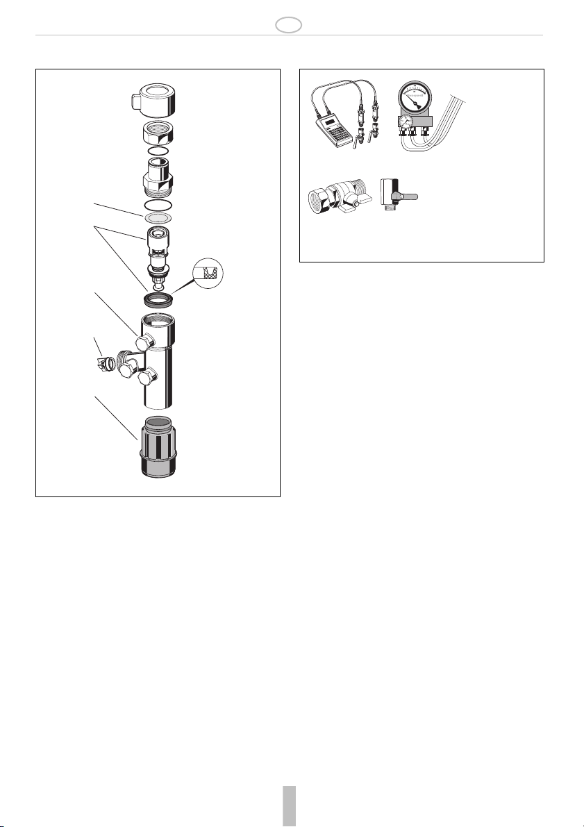
8.2.1 Kartuscheneinsatz
1. Absperrventil schließen
o Systemtrenner wird druckentlastet
2. Stopfen abschrauben
3. Kartuscheneinsatz, Nutring und Sieb ersetzen
o Kartusche eindrücken bis sie einrastet
4. Montage in umgekehrter Reihenfolge
5. Funktion überprüfen (siehe Kapitel Inspektion)
8.2.2 Rückflussverhinderer
1. Absperrventil schließen
o Systemtrenner wird druckentlastet
2. Rückflussverhinderer ersetzen
3. Funktion überprüfen (siehe Kapitel Inspektion)
Wir empfehlen einen Wartungsvertrag mit
einem Installationsunternehmen abzuschließen
• Intervall: alle 6 Monate (abhängig von den
örtlichen Bedingungen)
• Durchführung durch ein Installationsunter-
nehmen
• Inspektion mit Prüfgerät und Wartungsset
(siehe Zubehör)
Bedienungsanleitung Prüfgerät beachten
Der Öffnungsdruck kann am Prüfgerät ablesen
werden
Öffnungsdruck kleiner 0,14 bar Wartung!
Schnellprüfung der Funktion des Ablassventils:
• Vordruck absenken
o öffnet das Ablassventil (d.h. es tropft), so
ist die Funktion in Ordnung
Bedienungsanleitung Prüfgerät beachten
Druck nicht konstant Wartung!
• Intervall: min. einmal jährlich (abhängig von
den örtlichen Bedingungen)
• Durchführung durch ein Installationsunter-
nehmen
• Kartuscheneinsatz nicht in Einzelteile
zerlegen!

MU1H-1231GE23 R1106 5 Honeywell GmbH
D
8.3 Reinigung
Bei Bedarf können der Kartuscheneinsatz und der
Schmutzfänger gereinigt werden.
1. Absperrventile schließen
o Systemtrenner wird druckentlastet
2. Stopfen abschrauben
3. Schmutzfänger entfernen
4. Kartuscheneinsatz herausnehmen
5. Kartuscheneinsatz und Schmutzfänger reinigen.
6. Kartuscheneinsatz wieder einstecken.
7. Montage in umgekehrter Reihenfolge
8. Funktion überprüfen (siehe Kapitel Inspektion)
9. Entsorgung
• Gehäuse aus entzinkungsbeständigem Messing
(Variante A)
• Gehäuse aus Messing verchromt (Variante AC12)
• Kartuscheneinsatz aus hochwertigem Kunststoff
• Rückflussverhinderer aus hochwertigem Kunststoff
bzw. Rotguss
• Dichtelemente aus NBR und EPDM
• Ablaufanschluss aus hochwertigem Kunststoff
• Durchführung durch ein Installationsunter-
nehmen
• Durchführung durch den Betreiber
Zum Reinigen der Kunststoffteile keine
lösungsmittelhaltige Reinigungsmittel
benutzen!
Es dürfen keine Reinigungsmittel in die Umwelt
oder Kanalisation gelangen!
• Kartuscheneinsatz nicht in Einzelteile
zerlegen!
Die örtlichen Vorschriften zur ordnungsge-
mäßen Abfallverwertung bzw. Beseitigung
beachten!
10. Störungen / Fehlersuche
Störung Ursache Behebung
Ablassventil öffnet ohne ersicht-
lichen Grund
Druckschläge im Wassernetz Vor Systemtrenner einen Druckminderer
einbauen
Schwankender Vordruck Vor Systemtrenner einen Druckminderer
einbauen
Kartuscheneinsatz ist verschmutzt Kartuscheneinsatz ausbauen und reinigen
Ablassventil schließt nicht Ablagerungen am Ventilsitz Kartuscheneinsatz ausbauen und reinigen
oder ersetzen
Beschädigter O-Ring Kartuscheneinsatz ausbauen und ersetzen
Undichtes Ablassventil Kartuscheneinsatz ausbauen und reinigen
oder ersetzen
Zu geringer Durchfluss Eingangsseitiger Schmutzfänger ist
verstopft
Schmutzfänger ausbauen und reinigen

MU1H-1231GE23 R1106 6 Honeywell GmbH
D
11. Ersatzteile 12. Zubehör
1Kartuscheneinsatz 1/2" - 1" 0903733
2Rückflussverhin-
derereinsatz
1/2" - 1" 2110200
3Sieb 1/2" - 1" S295STN
4Verschluss-
stopfenset-MS für
Variante A
1/2" - 1" 0903889
5Verschlussstopfen-
set für Variante
AC12
1/2" - 1" 0903886
6Ablaufanschluss AT295
1
3
4, 5
2
6
TK295 Druck-Prüfset
Elektronisches Druckmessgerät mit Digitalan-
zeige, Batterie betrieben.
Mit Koffer und Zubehör, ideal zur Inspektion
und
Wartung der Systemtrenner BA.
TKA295Druck-Prüfset
Elektronisches Druckmessgerät mit
Differenzdruckanzeige.
Mit Koffer und Zubehör, ideal zur Inspektion
und
Wartung der Systemtrenner BA.
WS295STN Wartungsset
Wartungsset für Systemtrenner des Typs
BA295STN zur Verwendung mit Prüfgerät
TK295 bzw. TKA295
TK295 TKA295
1x 3x
WS295STN

MU1H-1231GE23 R1106 7 Honeywell GmbH
GB
1. Safety Guidelines
1. Follow the installation instructions.
2. Use the appliance
• according to its intended use
• in good condition
• with due regard to safety and risk of danger.
3. Note that the appliance is exclusively for use in the
applications detailed in these installation instruc-
tions. Any other use will not be considered to comply
with requirements and would invalidate the
warranty.
4. Please take note that any assembly, commis-
sioning, servicing and adjustment work may only be
carried out by authorized persons.
5. Immediately rectify any malfunctions which may
influence safety.
2. Functional description
BA type backflow preventers are divided into three
pressure zones. The pressure in zone is higher than
in zone , which in turn is higher than in zone . A
discharge valve is connected to zone which opens
at the latest when the differential pressure between
zones and falls to 0.14 bar. The water from zone
discharges to atmosphere. In this way the danger of
back pressure or back syphonage into the supply
network is prevented. The pipework connection is
interrupted and the drinking water network is
protected.
3. Application
Backflow preventers of this type are suitable for the
protection of drinking water systems against back
pressure, back flow and back syphonage.
They are used to protect the temporary water tapping
of standpipes on events or construction sites.
Fluids up to and including liquid category 4 to EN 1717
are protected.
4. Technical data
5. Scope of delivery
The backflow preventer consists of:
• Housing
• Integral strainer, mesh size approx. 0.4 mm
• Valve cartridge with integral check valve and
discharge valve
• Outlet check valve
• 3 test sockets
• Connection fittings
• Hose connection in 15° off-axis angle to avoid
bending of the hose
• Discharge connection
6. Options
7. Assembly
7.1 Installations Guidelines
• Installation downstream of outlet valve
• Backflow preventers of this type have an integral
strainer which protects the device from the ingress
of dirt
• The installation location should be protected against
frost
7.2 Assembly instructions
1. Close shutoff valves
2. Screw backflow preventer in shutoff valve
3. Fit coupling and flexible tube
4. The appliance is ready for use
5. Open shutoff valves
Medium Water
Maximum inlet pressure 10,0 bar
Minimum inlet pressure 1,5 bar
Installation conditions for the safe operation of the
appliance it’s not neccessary
to fullfill any height dimen-
sions
Installation position Vertical with discharge
valve downwards
Max. operating temperature 65°C
Discharge pipe connection DN50
Nominal diameter 3/4"
BA295STN-3/4A = Standard version with threaded
connections 1"
BA295STN-3/4AC12 =Housing chromium plated,
connecting thread 3/4"

Honeywell GmbH 8 MU1H-1231GE23 R1106
GB
8. Maintenance
8.1 Inspection
8.1.1 Testing discharge valve
1. Remove coupling and flexible tube
2. Fit outlet shutoff valve with sealing and close it
3. Remove blanking plugs
4. Fit ball valve with sealings and close them
5. Open inlet shutoff valve
6. Install suitable test control unit with relief valves
7. Open ball valve at zone and zone
8. Close inlet shutoff valve
9. Slowly open the vent valve at test control unit
o Pressure in zone relieves
10.Maintain the position of the relief valve and note the
differential pressure when one drop per minute
emits from the discharge valve as opening point of
the discharge valve
11.Close ball valve
12.Remove test control unit
13.Open outlet shutoff valve
14.Remove shutoff valve
15.Remove ball valves
16.Screw in blanking plugs
8.1.2 Testing outlet check valve
1. Remove coupling and flexible tube
2. Fit outlet shutoff valve with sealing and close it
3. Remove blanking plugs
4. Fit ball valve with sealings and close them
5. Open inlet shutoff valve
6. Install suitable test control unit with relief valves
7. Open ball valve zone
8. Close inlet shutoff valve
9. Open ball valve zone
o Pressure in zone stays constant, outlet check
valve is ready for use
10.Close ball valve
11.Remove test control unit
12.Open outlet shutoff valve
13.Remove shutoff valve
14.Remove ball valves
15.Screw in blanking plugs
8.2 Maintenance
8.2.1 Cartridge insert
1. Close shutoff valve
o Pressure in backflow preventer relieves
2. Unscrew the plug
3. Exchange cartridge insert, lip seal and filter
o push down the cartridge insert till it snaps in
4. Reassemble in reverse order
5. Test function (see chapter inspection)
8.2.2 Check valve
1. Close shutoff valve
o Pressure in backflow preventer relieves
2. Exchange check valve
3. Test function (see chapter inspection)
We recommend a planned maintenance
contract with an installation company
• Frequency: every 6 month (depending on
local operating conditions)
• To be carried out by an installation company
• Inspection with a test control unit and mainte-
nance-set (see accessories)
Take note of the instructions of the test control
unit
The opening pressure can be read off test
control unit
Opening pressure under 0,14 bar Mainte-
nance!
Quick test for the discharge valve:
• Lower the inlet pressure
o if the discharge valve opens (it drops), the
function is o.k.
Take note of the instructions of the test control
unit
Pressure stays not constant Maintenance!
• Frequency: at least once a year (depending
on local operating conditions)
• To be carried out by an installation company
• Don’t disassemble cartridge insert to indivi-
dual parts!

MU1H-1231GE23 R1106 9 Honeywell GmbH
GB
8.3 Cleaning
If necessary, the cartridge insert and the strainer can
be cleaned.
1. Close shutoff valve
o Pressure in backflow preventer relieves
2. Unscrew the plug
3. Remove strainer
4. Remove cartridge insert
5. Clean cartridge insert and strainer
6. Reinsert cartridge insert.
7. Reassemble in reverse order
8. Test function (see chapter inspection)
9. Disposal
• Dezincification resistant brass housing (Option A)
• Brass housing chromium plated (variant AC12)
• High-quality synthetic material valve cartridge
• High-quality synthetic material or red bronze check
valves
• Seals in NBR and EPDM
• High quality synthetic material discharge connection
• To be carried out by an installation company
• To be carried out by the operator
Do not use any cleaning agents containing
solvents or alcohol to clean the plastic parts!
Detergents must not be allowed to enter the
environment or the sewerage system!
• Don’t disassemble cartridge insert to indivi-
dual parts!
Observe the local requirements regarding
correct waste recycling/disposal!
10. Troubleshooting
Disturbance Cause Remedy
Discharge valve opens without
apparent reason
Pressure strokes in water supply system Install a pressure reducing valve
upstream the backflow preventer
Fluctuating inlet pressure Install a pressure reducing valve
upstream the backflow preventer
Cartridge insert is contaminated Remove cartridge insert and
exchange it
Discharge valve don’t close
Deposits on valve seat Remove cartridge insert and clean or
exchange it
Damaged ’o’ring Remove cartridge insert and
exchange it
Leaky discharge valve Remove cartridge insert and clean or
exchange it
Flow is to low Inlet strainer is blocked Remove strainer and clean it

MU1H-1231GE23 R1106 10 Honeywell GmbH
GB
11. Spare Parts 12. Accessories
1Cartridge insert 1/2" - 1" 0903733
2Check valve insert 1/2" - 1" 2110200
3Filter 1/2" - 1" S295STN
4Set of blanking
plugs-MS for
Option A
1/2" - 1" 0903889
5Set of blanking
plugs for Option
AC12
1/2" - 1" 0903886
6Discharge connec-
tion
AT295
1
3
4,5
2
6
TK295 Test kit
Electronic pressure measuring device with
digital indicator, runs by a battery.
With case and accessories, ideal for inspec-
tion and maintenance of backflow preventer
type BA.
TKA295 Test kit
Analogue pressure measuring device with
differential pressure display.
With case and accessories, ideal for inspec-
tion and maintenance of backflow preventer
type BA.
WS295STN Maintenance-set
Maintenance-set for BA295STN type back-
flow preventers for use with Test kit TK295
resp. TKA295
TK295 TKA295
1x 3x
WS295STN

MU1H-1231GE23 R1106 11 Honeywell GmbH
F
1. Consignes de sécurité
1. Suivre les indications de la notice de montage.
2. En ce qui concerne l'utilisation de l'appareil
• Utiliser cet appreil conformément aux données
constructeur
• Maintenir l'appareil en parfait état
• Respectez les consignes de sécurité
3. Il faut noter que cet équipement ne peut être mis en
oeuvre que pour les conditions d'utilisation menti-
onnées dans cette notice. Toute autre utilisation, ou
le non respect des conditions normales d'utilisation,
serait considérée comme non conforme.
4. Observer que tous les travaux de montage, de mise
en service, d'entretien et de réglage ne pourront
être effectués que par des spécialistes autorisés.
5. Prendre des mesures immédiates en cas d'anoma-
lies mettant en cause la sécurité.
2. Description fonctionnelle
Les disconnecteurs de type BA sont divisés en 3 zones
de pression. Dans la zone la pression est plus
élevée que dans la zone où elle est encore plus
élevée que dans la zone . A la zone une soupape
de vidange est raccordée et elle s'ouvre au plus tard
lorsque la pression différentielle entre la zone et
est tombée à 0,14 bar. L'eau de la zone s'écoule
vers l'extérieur. Ainsi, le risque de retour ou de réaspi-
ration dans le réseau de distribution est exclu. La
tuyauterie est interrompue et le réseau d'eau potable
est protégé.
3. Mise en oeuvre
Les disconnecteurs de ce type conviennent pour
protéger les installations d'eau potable contre la pres-
sion en retour, le retour d'eau et la réaspiration.
Ils sont utilisés pour protéger les tuyaux verticaux
servant à la prise d'eau temporaire lors de manifesta-
tions et sur des chantiers.
Ils permettent la protection des liquides jusqu'à la caté-
gorie de liquide 4 selon DIN EN 1717.
4. Caractéristiques
5. Contenu de la livraison
Le disconnecteur comprend:
• Corps
• Panier filtrant intégré, ouverture 0.4 mm
• Cartouche avec clapet anti-retour et soupape de
vidange intégrés
• Clapet anti-retour côté sortie
• 3 raccords d'inspection
• Raccords vissés
• Sortie disposée à un angle de 15° pour éviter des
plis dans un tuyau flexible raccordé
• Raccordement de sortie
6. Variantes
7. Montage
7.1 Dispositions à prendre
• Montage sous vanne de sortie
• Un panier filtrant est intégré au disconnecteur, il
n'est donc pas nécessaire de monter un filtre à part.
• Le lieu de montage doit être à l'abri du gel.
7.2 Instructions de montage
1. Fermer les robinets d'isolement.
2. Visser le disconnecteur sur le robinet d'isolement.
3. Monter l'accouplement GEKA et le tuyau flexible.
4. L'appareil est opérationnel.
5. Ouvrir les robinets d'isolement.
Fluide Eau
Pression d'admission maximale 10,0 bar
Pression d'admission minimale 1,5 bar
Conditions de montageil n'est pas nécessaire de
respecter certaines hauteurs
pour assurer le fonctionne-
ment sûr
Position de montage verticale, raccord de
sortie vers le bas
Température de service maxi65°C
Raccordement de sortie DN50
Dimensions de
raccordement
3/4"
BA295STN-3/4A = version standard avec raccord
fileté 1"
BA295STN-3/4AC12 =tier chromé, filetage de raccord
3/4"

Honeywell GmbH 12 MU1H-1231GE23 R1106
F
8. Maintenance
8.1 Inspection
8.1.1 Fonctionnement soupape de vidange
1. Démonter l'accouplement GEKA et le tuyau flexible.
2. Monter le robinet d'isolement avec joint côté sortie
et le fermer.
3. Enlever le bouchon.
4. Monter les robinets à boisseau sphérique avec joint
et les fermer.
5. Ouvrir le robinet d'isolement côté entrée.
6. Raccorder un appareil de contrôle adéquat muni de
soupapes de décharge.
7. Ouvrir les robinets à boisseau sphérique des cham-
bres à pression d'admission et moyenne pression
8. Fermer le robinet d'isolement côté entrée.
9. Ouvrir lentement la soupape de décharge à
l'appareil de contrôle.
o La chambre à pression d'admission est
déchargée.
10.Maintenir la position de la soupape de décharge et
noter comme pression d'ouverture de la soupape de
vidange la pression différentielle à laquelle une
goutte sort à peu près toutes les secondes de
l'orifice de sortie.
11.Fermer les robinets à boisseau sphérique.
12.Démonter l'appareil de contrôle.
13.Ouvrir le robinet d'isolement côté sortie.
14.Démonter le robinet d'isolement.
15.Démonter les robinets à boisseau sphérique.
16.Visser le bouchon.
8.1.2 Fonctionnement du clapet anti-retour côté
sortie
1. Démonter l'accouplement GEKA et le tuyau flexible.
2. Monter le robinet d'isolement avec joint côté sortie
et le fermer.
3. Enlever le bouchon.
4. Monter les robinets à boisseau sphérique avec joint
et les fermer.
5. Ouvrir le robinet d'isolement côté entrée.
6. Raccorder un appareil de contrôle adéquat muni de
soupapes de décharge.
7. Ouvrir le robinet à boisseau sphérique de la
chambre à pression d'entrée.
8. Fermer le robinet d'isolement côté entrée.
9. Ouvrir le robinet à boisseau sphérique de la
chambre à pression secondaire.
o La pression de la chambre à pression secondaire
est constante, le clapet anti-retour côté sortie est
opérationnel.
10.Fermer les robinets à boisseau sphérique.
11.Démonter l'appareil de contrôle.
12.Ouvrir le robinet d'isolement côté sortie.
13.Démonter le robinet d'isolement.
14.Démonter les robinets à boisseau sphérique.
15.Visser le bouchon.
Nous recommandons de conclure un contrat de
maintenance avec une entreprise d'installation.
• Intervalle : tous les 6 mois (en fonction des
conditions locales)
• Réalisation par une entreprise d'installation
• Inspection avec appareil de contrôle et kit
d'entretien (voir Accessoires)
Observer la notice d'utilisation de l'appareil de
contrôle.
La pression d'ouverture peut être lue à
l'appareil de contrôle.
Pression d'ouverture inférieure à 0,14 bar
Entretien !
Contrôle rapide du fonctionnement de la
soupape de vidange :
• Réduire la pression d'admission
o si la soupape de vidange s'ouvre (des
gouttes sortent), le fonctionnement est
correct.
Observer la notice d'utilisation de l'appareil de
contrôle.
Pression non constante Entretien !

MU1H-1231GE23 R1106 13 Honeywell GmbH
F
8.2 Entretien
8.2.1 Cartouche
1. Fermer le robinet d'isolement.
o Le disconnecteur est déchargé.
2. Dévisser le bouchon.
3. Remplacer la cartouche, le joint à gorge et le filtre.
o Appuyer sur la cartouche jusqu'à ce qu'elle
s'enclenche.
4. Montage dans l'ordre inverse
5. Contrôler le fonctionnement (voir chapitre Inspec-
tion)
8.2.2 Clapet anti-retour
1. Fermer le robinet d'isolement.
o Le disconnecteur est déchargé.
2. Remplacer le clapet anti-retour
3. Contrôler le fonctionnement (voir chapitre Inspec-
tion)
8.3 Nettoyage
En cas de besoin, la cartouche et le panier filtrant
peuvent être nettoyés.
1. Fermer les robinets d'isolement.
o Le disconnecteur est déchargé.
2. Dévisser le bouchon.
3. Enlever le panier filtrant.
4. Retirer la cartouche.
5. Nettoyer la cartouche et le panier filtrant.
6. Remonter la cartouche.
7. Montage dans l'ordre inverse
8. Contrôler le fonctionnement (voir chapitre Inspec-
tion)
9. Matériel en fin de vie
• Corps en laiton résistant à la dégalvanisation (Vari-
antes A)
• Bo tier en laiton chromé (variante AC12)
• Cartouche en matière synthétique de haute qualité
• Clapet anti-retour en matière synthétique de haute
qualité ou laiton rouge
• Eléments d'étanchéité en NBR et EPDM
• Intervalle : au moins une fois par an (en
fonction des conditions locales)
• Réalisation par une entreprise d'installation
• Ne pas démonter la cartouche !
• Réalisation par une entreprise d'installation
• Réalisation par l'exploitant
Ne pas utiliser de nettoyant qui contient des
solvants pour nettoyer les pièces en matière
synthétique !
Les nettoyants ne doivent pas pénétrer dans
l'environnement ou dans la canalisation !
• Ne pas démonter la cartouche !
Se conformer à la réglementation pour l'élimi-
nation des équipements industriels en fin de vie
vers les filières de traitement autorisées!
10. Défaut / recherche de panne
Panne Cause Remède
La soupape de vidange s'ouvre
sans raison manifeste
Coups de pression dans le réseau
d'eau
Monter un manodétendeur en amont du
disconnecteur
Variations de la pression d'admission Monter un manodétendeur en amont du
disconnecteur
Cartouche sale Retirer la cartouche et la nettoyer.
La soupape de vidange ne
ferme pas.
Dépôts sur le siège de soupape Démonter la cartouche et la nettoyer ou
remplacer.
Joint torique endommagé Retirer la cartouche et la remplacer.
Fuites à la soupape de vidange Démonter la cartouche et la nettoyer ou
remplacer.
Débit trop faible Le panier filtrant côté entrée est
bouché.
Retirer le panier filtrant et le nettoyer.

MU1H-1231GE23 R1106 14 Honeywell GmbH
F
11. Pièces de rechange 12. Accessoires
1Cartouche 1/2" - 1" 0903733
2Clapet anti-retour 1/2" - 1" 2110200
3Filtre 1/2" - 1" S295STN
4Kit de bouchons-
MS (Variantes A)
1/2" - 1" 0903889
5Kit de bouchons
(Variantes AC12)
1/2" - 1" 0903886
6Raccordement de
sortie
AT295
1
3
4, 5
2
6
TK295 Kit de contrôle de pression
Manomètre électronique avec affichage
numérique, à pile. Avec mallette et acces-
soires, idéal pour l'inspection et l'entretien des
disconnecteurs BA.
TKA295 Kit de contrôle de pression
Manomètre électronique avec affichage de
pression différentielle. Avec mallette et acces-
soires, idéal pour l'inspection et l'entretien des
disconnecteurs BA.
WS295STN Kit d'entretien
Kit d'entretien pour les disconnecteurs de
type BA295STN avec kit de contôle de
pression TK295 ou TKA295
TK295 TKA295
1x 3x
WS295STN

MU1H-1231GE23 R1106 15 Honeywell GmbH
PL
1. Wskazówki bezpieczeństwa
1. Przestrzegaćinstrukcji montażu.
2. Proszęużytkowaćprzyrząd
•zgodnie z jego przeznaczeniem
•w nienagannym stanie
•ze świadomościąbezpieczeństwa i zagrożeń
3. Proszęuwzględnić, że przyrząd przeznaczony jest
wyłącznie dla zakresu zastosowania określonego w
niniejszej instrukcji montażu. Każde inne lub
wykraczające poza to użytkowanie uznawane jest
jako niezgodne z przeznaczeniem.
4. Proszęuwzględnić, że wszystkie prace montażowe
mogąbyćwykonywane tylko przez autoryzowany
personel fachowy.
5. Wszystkie te zakłócenia, które mogąnaruszyć
bezpieczeństwo należy natychmiast usunąć.
2. Opis funkcji
Zespółodcinający typu BA zostałpodzielony na 3
strefy ciśnienia. W strefie ciśnienie jest wyższe niż
w strefie a tam z kolei jeszcze wyższe niżw strefie
. Do strefy podłączony zostałzawór spustowy
otwierający sięnajpóźniej w momencie, gdy różnica
ciśnieńpomiędzy strefąa spadnie do 0,14 bara.
Woda ze strefy wypływa na zewnątrz. Tym samym
wykluczone zostaje niebezpieczeństwo ze strony
ciśnienia wstecznego lub zassania zwrotnego do sieci
zasilającej. Rurociąg zostaje przerwany a siećwody
pitnej zabezpieczona.
3. Zastosowanie
Zespoły odcinające tego typu przeznaczone sądo
zabezpieczenia instalacji wody pitnej przed ciśnieniem
zwrotnym, cofnięciem, zassaniem zwrotnym.
Stosowane sądo zabezpieczenia stojaków
hydrantowych stosowanych do tymczasowego poboru
wody podczas imprez lub w warunkach budowlanych.
Zabezpieczone sąciecze łącznie z cieczami kategorii
4 zgodnie z DIN EN 1717.
4. Dane techniczne
5. Zakres dostawy
Zespółodcinający składa sięz:
•Obudowy
•Zintegrowanego osadnika zanieczyszczeń,
wielkość oczka 0,4 mm
•Wkładu kartuszowego ze zintegrowanym zaworem
przeciwzwrotnym i zaworem spustowym
•Zaworu przeciwzwrotnego na wyjściu
•3 króćców kontrolnych
•Połączeńśrubowych przyłączy
•Odgałęzienia pod kątem 15° zapobiegającego
załamywaniu siępodłączonego węża
•przyłącza spustowego
6. Warianty
7. Montaż
7.1 Zamontowanie
•Montażpod zaworem czerpalnym
•W zespole odcinającym zostałzamontowany
osadnik zanieczyszczeń, zatem nie trzeba
stosowaćoddzielnego osadnika
•Miejsce montażu musi byćzabezpieczone przed
mrozem
7.2 Instrukcja montażu
1. Zamknąć zawory odcinające
2. Przykręcićdo zaworu odcinającego zespół
odcinający
3. Zamontowaćsprzęgło GEKA i wąż
4. Urządzenie jest gotowe do pracy
5. Otworzyćotwory odcinające
Medium Woda
Maksymalne ciśnienie
wejściowe
10,0 bar
Minimalne ciśnienie
wejściowe
1,5 bar
Warunki montażu Do prawidłowego
funkcjonowania nie trzeba
przestrzegaćwysokości
instalacji
Pozycja montażowa prostopadle z przyłączem
odpływowym do dołu
Maks. temperatura
pracy
65°C
Przyłącze rury
spustowej
DN50
Rozmiar przyłącza 3/4"
BA295STN-3/4A = wersja standardowa z gwintem
przyłącza 1
BA295STN-3/4AC12 =Obudowa chromowana,
przyłącze gwintowane 3/4"

Honeywell GmbH 16 MU1H-1231GE23 R1106
PL
8. Utrzymywanie w dobrym stanie
8.1 Przegląd
8.1.1 Działanie zaworu spustowego
1. Zdemontowaćsprzęgło GEKA i wąż
2. Zamontowaćna wyjściu zawór odcinający z
uszczelnieniem i zamknąć go
3. Usunąć zaślepki
4. Zamontowaćzawory kulkowe z kurkiem oraz
uszczelnieniem i zamknąć je
5. Otworzyćzawór odcinający po stronie wejścia
6. Podłączyćodpowiedni przyrząd kontrolny z
zaworem odciążającym
7. Otworzyćzawory kulkowe z kurkiem komory
ciśnienia wstępnego i średniego
8. Zamknąć zawór odcinający po stronie wejścia
9. Otworzyćpowoli zawór odciążający na przyrządzie
kontrolnym
oCiśnienie w komorze ciśnienia wstępnego jest
redukowane
10.Zachowaćpozycjęzaworu odciążającego i
zanotowaćrożnicęciśnień, przy której z otworu
spustowego uchodzi około jedna kropla na
sekundę, jako ciśnienie otwarcia zaworu
spustowego
11.Zamknąć zawory kulkowe z kurkiem
12.Zdemontowaćprzyrząd kontrolny
13.Otworzyćzawór odcinający po stronie wyjścia
14.Zdemontowaćzawór odcinający
15.Zdemontowaćzawory kulkowe z kurkiem
16.Wkręcićzaślepki
8.1.2 Działanie zaworu przeciwzwrotnego na
wyjściu
1. Zdemontowaćsprzęgło GEKA i wąż
2. Zamontowaćna wyjściu zawór odcinający z
uszczelnieniem i zamknąć go
3. Usunąć zaślepki
4. Zamontowaćzawory kulkowe z kurkiem oraz
uszczelnieniem i zamknąć je
5. Otworzyćzawór odcinający po stronie wejścia
6. Podłączyćodpowiedni przyrząd kontrolny z
zaworem odciążającym
7. Otworzyćzawory kulkowe z kurkiem komory
ciśnienia wejściowego
8. Zamknąć zawór odcinający po stronie wejścia
9. Otworzyćzawory kulkowe z kurkiem komory
ciśnienia tylnego
oCiśnienie w komorze ciśnienia tylnego stałe,
zawór przeciwzwrotny na wyjściu jest gotowy do
pracy
10.Zamknąć zawory kulkowe z kurkiem
11.Zdemontowaćprzyrząd kontrolny
12.Otworzyćzawór odcinający po stronie wyjścia
13.Zdemontowaćzawór odcinający
14.Zdemontowaćzawory kulkowe z kurkiem
15.Wkręcićzaślepki
8.2 Konserwacja
8.2.1 Wkład kartuszowy
1. Zamknąć zawory odcinające
o W zespole odcinającym ciśnienie redukowane jest
do zera
2. Odkręcićzaślepki
3. Wymienićwkład kartuszowy, pierścieńrowkowany
oraz sito
Zalecamy zawarcie umowy na konserwacjęz
firmąinstalacyjna
•Okres: co 6 miesięcy (w zależności od
panujących na miejscu warunków)
•Kontrola przeprowadzana przez firmę
instalacyjną
•Przegląd przy użyciu przyrządu kontrolnego
i zestawu do konserwacji (zob. akcesoria)
Przestrzegaćinstrukcji obsługi przyrządu
kontrolnego
Ciśnienie otwarcia można odczytaćna
przyrządzie kontrolnym
Ciśnienie otwarcia mniejsze niż
Konserwacja!
Szybka kontrola działania zaworu spustowego:
•Zredukowaćciśnienie wstępne
oJeśli zawór spustowy sięotwiera (tzn.
kapie), to wskazuje to na prawidłowe
działanie
Przestrzegaćinstrukcji obsługi przyrządu
kontrolnego
Ciśnienie nie jest stałe Konserwacja!
•Okres: przynajmniej raz w roku (w zależności
od panujących na miejscu warunków)
•Kontrola przeprowadzana przez firmę
instalacyjną

MU1H-1231GE23 R1106 17 Honeywell GmbH
PL
oWciskaćkartusz ażdo zakleszczenia
4. Montażw odwrotnej kolejności
5. Sprawdzićdziałanie (zob. rozdziaąPrzegląd)
8.2.2 Zawór przeciwzwrotny
1. Zamknąć zawory odcinające
o W zespole odcinającym ciśnienie redukowane jest
do zera
2. Wymienićzawór przeciwzwrotny
3. Sprawdzićdziałanie (zob. rozdziaąPrzegląd)
8.3 Czyszczenie
W razie potrzeby można oczyścićwkład kartuszowy
oraz osadnik zanieczyszczeń.
1. Zamknąć zawory odcinające
o W zespole odcinającym ciśnienie redukowane jest
do zera
2. Odkręcićzaślepki
3. Usunąć osadnik zanieczyszczeń
4. Wyjąć wkład kartuszowy
5. Oczyścićwkład kartuszowy oraz osadnik
zanieczyszczeń.
6. Włożyćz powrotem wkład kartuszowy.
7. Montażw odwrotnej kolejności
8. Sprawdzićdziałanie (zob. rozdziaąPrzegląd)
9. Usuwanie
•Obudowa z mosiądzu odpornego na odcynkowanie
(Warianty A)
•Obudowa mosina chromowana (wersja AC12)
•Wkład kartuszowy z wysokiej jakości tworzywa
sztucznego
•Zawór przeciwzwrotny z wysokiej jakości tworzywa
sztucznego lub mosiądzu czerwonego
•Elementy uszczelniające z NBR i EPDM
•Nie rozkładaćna części wkładu
kartuszowego!
•Kontrola przeprowadzana przez firmę
instalacyjną
•Przeprowadzane przez eksploatującego
Do czyszczenia elementów z tworzyw
sztucznych nie stosowaćśrodków
czyszczących zawierających rozpuszczalniki!
ze środków czyszczących nie mogądostaćsię
do środowiska lub kanalizacji!
•Nie rozkładaćna części wkładu
kartuszowego!
Należy stosowaćsiędo miejscowych
przepisów dotyczących prawidłowego
wykorzystania odpadów wzgl. ich usuwania!
10. Zakłócenia / poszukiwanie usterek
Usterka Przyczyna Usuwanie
Zawór spustowy otwiera bez
wyraźnej przyczyny
Uderzenie ciśnienia w sieci wodnej Zainstalowaćprzed zespołem
odcinającym reduktor ciśnienia
Zmienne ciśnienie wstępne Zainstalowaćprzed zespołem
odcinającym reduktor ciśnienia
Wkład kartuszowy jest zabrudzony Wymontowaći oczyścićwkład kartuszowy
Zawór spustowy nie zamyka Osad przy przy gnieździe zaworu Wymontowaći oczyścićlub wymienić
wkład kartuszowy
Uszkodzony pierścieńtypu O-ring Wymontowaći wymienićwkład
kartuszowy
Nieszczelny zawór spustowy Wymontowaći oczyścićlub wymienić
wkład kartuszowy
Zbyt mały przepływ Osadnik zanieczyszczeńpo stronie
wejścia jest zatkany
Wymontowaći oczyścićosadnik
zanieczyszczeń

MU1H-1231GE23 R1106 18 Honeywell GmbH
PL
11. Części zamienne 12. Wyposażenie dodatkowe
1Wkład kartuszowy 1/2" - 1" 0903733
2WkBad zaworu
przeciwzwrotnego
1/2" - 1" 2110200
3Sito 1/2" - 1" S295STN
4Zestaw zaślepek-
MS (Warianty A)
1/2" - 1" 0903889
5Zestaw zaślepek
f(Warianty AC12)
1/2" - 1" 0903886
6Przyłącze
spustowe
AT295
1
3
4, 5
2
6
TK295 Zestaw do kontroli ciśnienia
Elektroniczny przyrząd pomiarowy z
cyfrowym wyświetlaczem, zasilany z baterii.
Z futerałem i akcesoriami, idealny do
przeprowadzania przeglądów i konserwacji
zespołów odcinających BA.
TKA295 Zestaw do kontroli ciśnienia
Elektroniczny przyrząd pomiarowy z
cyfrowym wyświetlaniem różnicy ciśnień. Z
futerałem i akcesoriami, idealny do
przeprowadzania przeglądów i konserwacji
zespołów odcinających BA.
WS295STN Zestaw do konserwacji
Zestaw do konserwacji do zespołu
odcinającego typu BA295STN
TK295 TKA295
1x 3x
WS295STN

Honeywell GmbH 19 MU1H-1231GE23 R1106
PL

Automation and Control Solutions
Honeywell GmbH
Hardhofweg
D-74821 Mosbach
Phone: (49) 6261 810
Fax: (49) 6261 81309
http://europe.hbc.honeywell.com
www.honeywell.com
Manufactured for and on behalf of the
Environmental and Combustion Controls Division of
Honeywell Technologies Sàrl, Ecublens, Route du
Bois 37, Switzerland by its Authorised
Representative Honeywell GmbH
EN0H-1231GE23 R1106
Subject to change
© 2006 Honeywell GmbH
Table of contents
Languages:
Other Honeywell Water System manuals
Popular Water System manuals by other brands

Everpure
Everpure Sediment Filter Wrap EV9799-04 Specification sheet

Taco Comfort Solutions
Taco Comfort Solutions 1900e Series instruction sheet

Everpure
Everpure RFFE 20-BB5 Replacement Cartridge DEV9108-46 Specification sheet

EnerWorks
EnerWorks EWRA2 installation manual

Nexus
Nexus JP-103 Operation manual

Dewhot
Dewhot LPDH 5 manual

Omnifilter
Omnifilter B2000 Installation, operation and maintenance manual

Alpha
Alpha OKU Instructions for installation, use and maintenance

TERRY
TERRY SM2 Specifications

Marlo Incorporated
Marlo Incorporated RO-25T operating manual

GrowMax Water
GrowMax Water MAXQUARIUM 000PPM manual

Everpure
Everpure SSFM-100M-15 Specification sheet