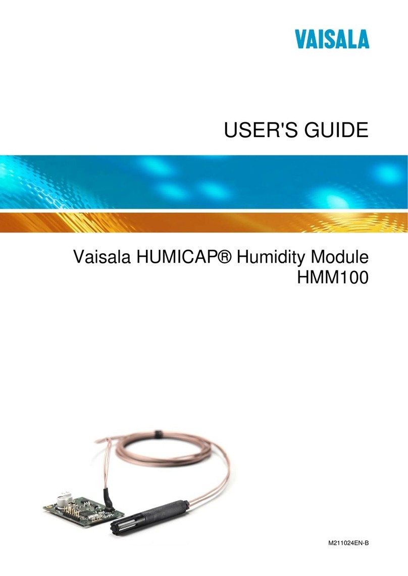
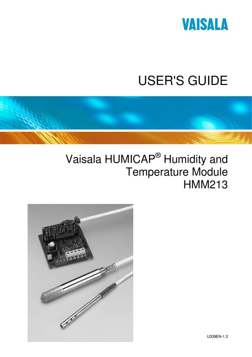
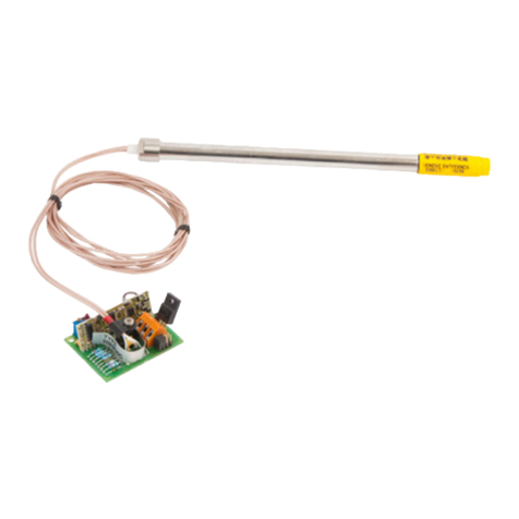
Vaisala HUMICAP HMM100 User manual

M211024EN-D
User Guide
Vaisala HUMICAPâHumidity Module
HMM100

PUBLISHED BY
Vaisala Oyj
Street address: Vanha Nurmijärventie 21, FI-01670 Vantaa, Finland
Mailing address: P.O. Box 26, FI-00421 Helsinki, Finland
Phone: +358 9 8949 1
Visit our Internet pages at www.vaisala.com.
© Vaisala Oyj 2018
No part of this manual may be reproduced,
published or publicly displayed in any form or by
any means, electronic or mechanical (including
photocopying), nor may its contents be modified,
translated, adapted, sold or disclosed to a third
party without prior written permission of the
copyright holder. Translated manuals and
translated portions of multilingual documents are
based on the original English versions. In
ambiguous cases, the English versions are
applicable, not the translations.
The contents of this manual are subject to change
without prior notice.
Local rules and regulations may vary and they
shall take precedence over the information
contained in this manual. Vaisala makes no
representations on this manual’s compliance with
the local rules and regulations applicable at any
given time, and hereby disclaims any and all
responsibilities related thereto.
This manual does not create any legally binding
obligations for Vaisala towards customers or end
users. All legally binding obligations and
agreements are included exclusively in the
applicable supply contract or the General
Conditions of Sale and General Conditions of
Service of Vaisala.
This product contains software developed by
Vaisala or third parties. Use of the software is
governed by license terms and conditions
included in the applicable supply contract or, in
the absence of separate license terms and
conditions, by the General License Conditions of
Vaisala Group.

Table of Contents
1. About This Document..................................................................................... 5
1.1 Version Information.............................................................................................5
1.2 Related Manuals...................................................................................................5
1.3 Documentation Conventions............................................................................. 5
1.4 Trademarks...........................................................................................................6
1.5 Patent Notice....................................................................................................... 6
2. Product Overview............................................................................................. 9
2.1 Introduction to HMM100 Series Humidity Modules.........................................9
2.2 Basic Features and Options..............................................................................10
2.3 Probe Types........................................................................................................10
2.4 Filter Types...........................................................................................................11
2.5 Installation Accessories..................................................................................... 12
2.5.1 Probe Mounting Flange...............................................................................12
2.5.2 Probe Mounting Clamp............................................................................... 13
2.5.3 Mounting Bracket with Lid......................................................................... 13
2.5.4 Module Housing (IP65)...............................................................................14
2.6 Safety.................................................................................................................. 14
2.6.1 ESD Protection............................................................................................. 15
2.7 Regulatory Compliances................................................................................... 15
3. Installation.......................................................................................................... 17
3.1 Dimensions..........................................................................................................17
3.2 Installing the Module......................................................................................... 18
3.3 Installing the Probe............................................................................................18
3.3.1 Mounting HMM100 Probe to Mounting Clamp.........................................19
3.4 Wiring.................................................................................................................. 21
3.4.1 2-wire Output...............................................................................................21
3.4.2 3-wire Output...............................................................................................21
3.5 Verifying Installation......................................................................................... 22
4. Operation........................................................................................................... 23
4.1 Using Service Port.............................................................................................23
4.1.1 Installing Driver for USB Cable..................................................................23
4.1.2 Terminal Application Settings...................................................................24
4.2 List of Serial Commands...................................................................................25
4.3 Device Information and Status........................................................................ 27
4.3.1 Show Device Information...........................................................................27
4.3.2 Show Quantities..........................................................................................27
4.3.3 Show Calibration Info.................................................................................28
4.3.4 Show Analog Output Status......................................................................28
4.3.5 Show Firmware Version............................................................................. 29
4.4 Serial Line Output Commands........................................................................ 29
4.4.1 Start Measurement Output........................................................................29
4.4.2 Stop Measurement Output........................................................................30
4.4.3 Set Output Interval.....................................................................................30
4.4.4 Output a Reading Once.............................................................................30
Table of Contents
1

4.5 Calibration Commands......................................................................................31
4.5.1 Calibrate Temperature Measurement........................................................31
4.5.2 Calibrate Humidity Measurement............................................................. 32
4.5.3 View User Adjustment Parameters...........................................................33
4.5.4 Set User Adjustment Parameters............................................................. 33
4.5.5 Zero the Trimmers...................................................................................... 34
4.5.6 Calibrate Analog Output........................................................................... 34
4.6 Configuring Serial Line Operation...................................................................35
4.6.1 Set Serial Line Settings.............................................................................. 35
4.6.2 Set Terminal Echo.......................................................................................36
4.6.3 Set Module Address................................................................................... 36
4.6.4 Set Serial Interface Mode...........................................................................37
4.7 Configuring Measurement Parameters.......................................................... 38
4.7.1 Set Environmental Compensation Values............................................... 38
4.7.2 Set Temporary Pressure Compensation Value........................................39
4.8 Configuring Analog Output............................................................................. 39
4.8.1 Set Analog Output Mode...........................................................................39
4.8.2 Select Analog Output Quantity and Scaling.......................................... 40
4.8.3 Test Analog Output..................................................................................... 41
4.9 Other Commands..............................................................................................42
4.9.1 Display Command List............................................................................... 42
4.9.2 Enable Advanced Commands...................................................................42
4.9.3 Display Currently Active Errors.................................................................42
4.9.4 Connecting to the Module in POLL Mode............................................... 43
4.9.5 Closing the Connection in POLL Mode.................................................... 43
4.9.6 Save Changed Settings..............................................................................43
4.9.7 Restore Saved Settings............................................................................. 44
4.9.8 Reset the Module....................................................................................... 44
4.9.9 Restore Factory Settings...........................................................................44
5. Maintenance...................................................................................................... 47
5.1 Changing Filter..................................................................................................47
5.2 Changing Sensor............................................................................................... 47
5.3 Calibration......................................................................................................... 49
5.4 Calibration and Adjustment Using Trimmers................................................ 50
5.5 Calibration and Adjustment Using Serial Line................................................51
5.5.1 Temperature Calibration (CT).................................................................... 51
5.5.2 Humidity Calibration (CRH)...................................................................... 54
6. Troubleshooting...............................................................................................57
6.1 Analog Output Error Notification....................................................................57
6.2 Problems and Their Possible Solutions.......................................................... 57
7. Technical Data..................................................................................................59
7.1 Dimensions........................................................................................................ 62
7.2 Accessories........................................................................................................ 62
Warranty........................................................................................................................65
Technical Support......................................................................................................65
Recycling.......................................................................................................................65
HMM100 User Guide M211024EN-D
2

List of Figures
Figure 1 HMM100 Humidity Module with Probe.......................................................... 9
Figure 2 Probe Types...........................................................................................................11
Figure 3 Extended 400-mm Plastic Probe....................................................................11
Figure 4 Optional Probe Mounting Flange...................................................................12
Figure 5 HMM100 Probe with Mounting Clamp.......................................................... 13
Figure 6 Mounting Bracket with Lid...............................................................................14
Figure 7 Optional Module Housing.................................................................................14
Figure 8 HMM100 Dimensions. Left to Right: Standard and
Extended Probe Body....................................................................................... 17
Figure 9 Component Board (3-wire Version)..............................................................18
Figure 10 Wiring for 2-wire Output.................................................................................. 21
Figure 11 Wiring for 3-wire Output................................................................................. 22
Figure 12 PuTTY Terminal Application........................................................................... 25
Figure 13 Changing the Sensor........................................................................................ 49
Figure 14 Trimmers for Oset and Gain.........................................................................50
Figure 15 Loop Supply Voltage Versus Loop Resistance..........................................60
Figure 16 HMM100 Dimensions. Top to Bottom: Standard and
Extended Probe Body...................................................................................... 62
List of Figures
3

List of Tables
Table 1 Document Versions................................................................................................5
Table 2 Related Manuals..................................................................................................... 5
Table 3 Applicable Patents.................................................................................................6
Table 4 Quantities Measured by HMM100......................................................................9
Table 5 Filter Types and Properties................................................................................. 11
Table 6 HMM100 Default Serial Interface Settings.................................................... 24
Table 7 Basic Serial Commands......................................................................................25
Table 8 Advanced Serial Commands.............................................................................26
Table 9 Error Levels for Analog Output Modes.......................................................... 57
Table 10 Measurement Performance...............................................................................59
Table 11 Operating Environment..................................................................................... 59
Table 12 Inputs and Outputs.............................................................................................60
Table 13 HMM100 3-wire Model Current Consumption.............................................60
Table 14 Mechanical Specifications.................................................................................. 61
Table 15 Spare Parts and Accessories.............................................................................62
HMM100 User Guide M211024EN-D
4

1. About This Document
1.1 Version Information
This document provides instructions for installing, operating, and maintaining Vaisala
HUMICAPâHumidity Module HMM100.
Table 1 Document Versions
Document Code Date Description
M211024EN-D March 2018 This manual. Added information on the following:
• HUMICAPâR2 and HUMICAPâ180V humidity sensor
• Extended 400‑mm‑long option for the plastic probe
• PPS plastic grid with stainless steel net filter option
Removed information on the catalytic VHP filter.
M211024EN-C November 2013 Removed RHCAL command. Added information on which parameter
changes must be saved separately and which are saved automatically.
M211024EN-B October 2012 Added VHP filter option and new pictures to the installation
instructions, edited commands and technical specifications.
1.2 Related Manuals
Table 2 Related Manuals
Document Code Name
M210185EN Vaisala Humidity Calibrator HMK15 User's Guide
M211002EN Vaisala HUMICAP
â
Humidity Module HMM100 Quick Reference Guide
M211078EN Module Housing (IP65) for Humidity Module HMM100 Quick Reference Guide
M211079EN Mounting Bracket for Humidity Module HMM100 Quick Reference Guide
M211080EN Mounting Flange for Humidity Probes Quick Reference Guide
1.3 Documentation Conventions
Warning alerts you to a serious hazard. If you do not read and follow
instructions carefully at this point, there is a risk of injury or even death.
WARNING!
Chapter 1 – About This Document
5

Caution warns you of a potential hazard. If you do not read and follow
instructions carefully at this point, the product could be damaged or important data
could be lost.
CAUTION!
Note highlights important information on using the product.
Tip gives information for using the product more eciently.
Lists tools needed to perform the task.
Indicates that you need to take some notes during the task.
1.4 Trademarks
Vaisalaâand HUMICAPâare registered trademarks of Vaisala Oyj.
Windowsâis either a registered trademark or trademark of Microsoft Corporation in the
United States and other countries.
All other product or company names that may be mentioned in this publication are trade
names, trademarks, or registered trademarks of their respective owners.
1.5 Patent Notice
This product is protected by the following patents and their corresponding national rights:
Table 3 Applicable Patents
Issuing Oce Publication Number
Finnish Patent and Registration Oce Finnish patent 98861
National Institute of Industrial Property French patent 6650303
German Patent and Trade Mark Oce German patent 69418174
HMM100 User Guide M211024EN-D
6

Issuing Oce Publication Number
Japan Patent Oce Japanese patent 3585973
Intellectual Property Oce UK patent 0665303
United States Patent and Trademark Oce U.S. patent 5607564
Chapter 1 – About This Document
7

HMM100 User Guide M211024EN-D
8

2. Product Overview
2.1 Introduction to HMM100 Series
Humidity Modules
Figure 1 HMM100 Humidity Module with Probe
The HMM100 series humidity measurement modules are open frame modules intended for
integration into environmental chambers and other chambers where high temperature
tolerance is important. The modules provide a single analog output channel for relative
humidity (RH) or dewpoint (Td). Dewpoint is the recommended quantity if the measurement
environment has significant temperature dierences.
Table 4 Quantities Measured by HMM100
Quantity Range
Relative humidity (RH) 0 ... 100 %
Dewpoint (Td) -20 ... +100 °C (-4 ... +212 °F)
All HMM100 modules include automatic temperature compensation across the operating
temperature range using an integrated Pt1000 sensor. No external temperature
compensation should be applied to the output.
HMM100 modules do not incorporate probe heating or chemical purge functionality. If the
measurement environment is prone to condensation, or likely to cause chemical
contamination of the sensor, other Vaisala instruments may be more suitable to the
application.
Chapter 2 – Product Overview
9

The cable and probe of the HMM100 are attached at the factory. They should remain
connected to the module at all times; do not cut and re-connect the cable.
2.2 Basic Features and Options
• Vaisala HUMICAPâR2 humidity sensor
• Plastic or stainless steel probe
• The plastic probe is available in two sizes, a standard one and an extended 400-mm-
long option
• Analog output options:
• 4 ... 20 mA loop powered (2-wire output model)
• 0 ... 20 mA or 0 ... 1/5/10 V (3-wire output model, user-configurable using service
port)
• Cable lengths:
• 0.65 m, 1.55 m, or 2.9 m for the standard plastic probe, and 1.55 m for the extended
400-mm-long probe
• 1.55 m or 2.9 m for the stainless steel probe
• Various filter types
• Optional installation accessories:
• Probe mounting flange
• Probe mounting clamp
• Mounting bracket with lid
• Module housing (IP65)
• Service port for maintenance
• Optional USB cable for easy access
More Information
‣Probe Types (page 10)
‣Filter Types (page 11)
‣Installation Accessories (page 12)
‣Using Service Port (page 23)
2.3 Probe Types
The HMM100 can be ordered with a plastic or stainless steel probe. The plastic probe is
available in two sizes, a standard one and an extended 400-mm-long option. The plastic
probe is suitable for most applications.
The standard plastic probe and the steel probe have the same operational temperature
range (-70 °C to +180 °C). The extended 400-mm plastic probe is suitable for temperatures
ranging from -70 °C to +120 °C. Note that the operational temperature range is also aected
by the filter; see Filter Types (page 11).
Figure 2 (page 11) shows the plastic probe with a membrane filter (top), and the stainless
steel probe with a sintered stainless steel filter (bottom).
HMM100 User Guide M211024EN-D
10

Figure 2 Probe Types
Figure 3 Extended 400-mm Plastic Probe
2.4 Filter Types
All filters available for HMM100 are 12 mm in diameter, and can be used in both the plastic
and stainless steel probe. Note the operational temperature range of each filter. For order
codes, see Accessories (page 62).
Table 5 Filter Types and Properties
Filter Type Diameter Pore Size Temperature Range
Plastic grid (fastest
response time)
12 mm - -20 ... +80 °C (-4 ... +176 °F)
Membrane 12 mm 0.2 µm -20 ... +80 °C (-4 ... +176 °F)
Chapter 2 – Product Overview
11

Filter Type Diameter Pore Size Temperature Range
Porous PTFE
(general purpose)
12 mm 8 µm -70 ... +180 °C (-94 ... +356 °F)
Stainless steel
sintered
12 mm 38 µm -70 ... +180 °C (-94 ... +356 °F)
PPS plastic grid with
stainless steel net
12 mm 15 µm -70 ... +180 °C (-94 ... +356 °F)
2.5 Installation Accessories
For order codes of installation accessories, see Accessories (page 62).
2.5.1 Probe Mounting Flange
The probe mounting flange is used to seal the cable pass-through in the chamber wall. The
flange can also be used to hold the probe itself, in case the probe cannot be mounted on the
chamber wall otherwise. This mounting is not ideal since leaving the probe cable completely
outside the measurement environment may cause heat conduction that aects the
measurement. Therefore, installation using mounting flange is recommended for the 400-
mm-long probe option only, as the risk of heat conduction to the sensor is smaller than with
the shorter, standard-length probe.
Figure 4 Optional Probe Mounting Flange
HMM100 User Guide M211024EN-D
12

2.5.2 Probe Mounting Clamp
The optional mounting clamp makes it easy to install the probe on the wall of the
measurement environment. The probe can be detached for calibration simply by loosening
the lower screw.
Installing the entire probe in the measurement environment prevents heat conduction to the
sensor, and is the recommended installation method.
Figure 5 HMM100 Probe with Mounting Clamp
Use 2 mounting clamps for stability when installing the longer, 400-mm plastic probe.
More Information
‣Mounting HMM100 Probe to Mounting Clamp (page 19)
2.5.3 Mounting Bracket with Lid
The optional mounting bracket includes a metal backplate and a plastic lid for the
component board. The bracket does not provide IP rated protection. The bracket can be
installed on a DIN rail.
Chapter 2 – Product Overview
13

Figure 6 Mounting Bracket with Lid
2.5.4 Module Housing (IP65)
The optional module housing is an IP65 rated housing. The module is installed inside the
housing in a mounting bracket (provided with the housing). The housing has two cable
glands. A coaxial plug is provided for sealing the gland for the probe cable.
Figure 7 Optional Module Housing
2.6 Safety
The module delivered to you has been tested for safety and approved as shipped from the
factory. Note the following precautions:
Ground the product and verify installation grounding periodically to
minimize shock hazard.
WARNING!
HMM100 User Guide M211024EN-D
14

Do not modify the unit or use it in ways not described in the documentation.
Improper modification may lead to safety hazards, equipment damage, failure to
perform according to specification, or decreased equipment lifetime.
CAUTION!
2.6.1 ESD Protection
Electrostatic Discharge (ESD) can cause immediate or latent damage to electronic circuits.
Vaisala products are adequately protected against ESD for their intended use. However, it is
possible to damage the product by delivering an electrostatic discharge when touching,
removing or inserting any objects inside the equipment housing.
Avoid touching component contacts or connectors when working with the device.
2.7 Regulatory Compliances
The HMM100 is in conformity with the provisions of the following EU directive(s):
• RoHS Directive
• WEEE Directive
The electromagnetic compatibility of the HMM100 has been tested according to the
following product family standard:
EN61326-1 Electrical equipment for measurement, control and laboratory use - EMC
requirements - for use in light industrial environments.
The Electrostatic Discharge test (EN 61000-4-2) was not applied to the open frame module.
In the final product the module PC-board should be installed in a user restricted location /
enclosure for continued ESD protection.
Chapter 2 – Product Overview
15

HMM100 User Guide M211024EN-D
16

3. Installation
3.1 Dimensions
55
[2.16]
30.7
[1.21]
Ø12
[0.47]
46.5
[1.83]
36.5
[1.44]
55
[2.17]
49
[1.93]
Ø3.5
[0.14]
M10x1
362
[14.25]
41.0
[1.61]
Ø12
[0.47]
mm
[in]
Figure 8 HMM100 Dimensions. Left to Right: Standard and Extended Probe Body
Chapter 3 – Installation
17

3.2 Installing the Module
The measurement probe with cable is attached to the component board at Vaisala. Do not
disconnect and reconnect the cable.
1. Attach the module securely using the mounting holes on the corners of the component
board. Use the optional mounting bracket (Vaisala order code 225979) if needed.
2. Make sure that the module has a good earth connection from the plated mounting hole.
The installation holes on the component board are compatible with Vaisala HMM22 and
HMM30 humidity modules. Remember to disable temperature compensation (if any) in
the measurement system when replacing an old module with the HMM100. The
temperature compensation in the HMM100 is always enabled.
OFFSET GAIN
+ OUT - + Vin -
Figure 9 Component Board (3-wire Version)
3.3 Installing the Probe
1. Select the mounting location for the probe.
• The probe should be entirely in the measurement environment, with sucient
distance to the outer walls of the chamber or duct. Air should flow freely around the
probe.
• The probe location should represent well the environmental or process conditions,
and it should be as clean as possible.
HMM100 User Guide M211024EN-D
18
Other manuals for HUMICAP HMM100
2
Table of contents
Other Vaisala Control Unit manuals