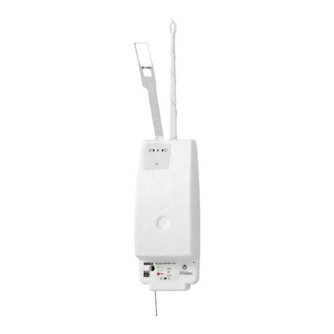
Vaisala QBR101 User manual

Battery Regulator
QBR101
USER'S GUIDE
M210374en-A
March 2003

PUBLISHED BY
Vaisala Oyj Phone (int.): +358 9 8949 1
P.O. Box 26 Fax: +358 9 8949 2227
FIN-00421 Helsinki
Finland
Visit our Internet pages at http://www.vaisala.com/
© Vaisala 2003
No part of this manual may be reproduced in any form or by any means,
electronic or mechanical (including photocopying), nor may its contents be
communicated to a third party without prior written permission of the copyright
holder.
The contents are subject to change without prior notice.
Please observe that this manual does not create any legally binding obligations for
Vaisala towards the customer or end user. All legally binding commitments and
agreements are included exclusively in the applicable supply contract or
Conditions of Sale.

_________________________________________________________________________________
VAISALA_________________________________________________________________________ 1
Table of Contents
CHAPTER 1
GENERAL INFORMATION............................................................................ 3
About This Manual ................................................................... 3
Contents of This Manual ....................................................... 3
Version Information ............................................................... 3
Feedback............................................................................... 4
Safety......................................................................................... 4
General Safety Considerations ............................................. 4
ESD Protection...................................................................... 4
Warranty .................................................................................... 5
Technical Support .................................................................... 5
CHAPTER 2
PRODUCT OVERVIEW.................................................................................. 7
Introduction to QBR101 Battery Regulator............................ 7
Charger...................................................................................... 9
Control Circuit .......................................................................... 9
CHAPTER 3
INSTALLATION............................................................................................ 11
Connections............................................................................ 11
Jumpers and LEDs................................................................. 13
Jumpers for Charge Current Limit....................................... 13
Jumper for Battery Voltage Select ...................................... 13
LEDs.................................................................................... 13
Mechanical Installation .......................................................... 14
CHAPTER 4
TECHNICAL DATA ...................................................................................... 15
Specifications ......................................................................... 15
Charge Voltage Adjustment .................................................. 16
Temperature Compensation NTC....................................... 17
List of Figures
Figure 1 Functional Block Diagram of QBR101 ....................................... 8
Figure 2 Adjustment of Current Limit...................................................... 13
Figure 3 Installation Hole Dimensions .................................................... 14

User's Guide _______________________________________________________________________
2 _____________________________________________________________________M210374en-A
List of Tables
Table 1 Manual Revisions .......................................................................3
Table 2 Input Connector X1...................................................................11
Table 3 Output Connector X2................................................................12
Table 4 Control Connector X3 ...............................................................12
Table 5 QBR101 Electrical Performance Specifications .......................15
Table 6 QBR101 Environmental Specifications.....................................16
Table 7 QBR101 Mechanical Specifications .........................................16
Table 8 Voltage Selection Resistor Value vs. Charging voltage
(typ. @ +25 °C) and Battery Type ............................................17

Chapter 1 _________________________________________________________ General Information
VAISALA_________________________________________________________________________ 3
CHAPTER 1
GENERAL INFORMATION
About This Manual
This manual provides information for installing and operating the
QBR101 Battery Regulator.
Contents of This Manual
This manual consists of the following chapters:
- Chapter 1, General Information, provides important safety, revision
history, and warranty information for the product.
- Chapter 2, Product Overview, introduces the QBR101 Battery
Regulator features and advantages.
- Chapter 3, Installation, provides you with information that is
intended to help you install this product.
- Chapter 4, Technical Data, provides the technical data of QBR101
Battery Regulator.
Version Information
Table 1 Manual Revisions
Manual Code Description
M210374en-A QBR101 Battery Regulator User's Guide (this manual)

User's Guide _______________________________________________________________________
4 _____________________________________________________________________M210374en-A
Feedback
Vaisala Customer Documentation Team welcomes your comments
and suggestions on the quality and usefulness of this publication. If
you find errors or have other suggestions for improvement, please
indicate the chapter, section, and page number. You can send
Safety
General Safety Considerations
Throughout the manual, important safety considerations are
highlighted as follows:
WARNING Warning alerts you to a serious hazard. If you do not read and follow
instructions very carefully at this point, there is a risk of injury or
even death.
CAUTION Caution warns you of a potential hazard. If you do not read and
follow instructions carefully at this point, the product could be
damaged or important data could be lost.
NOTE Note highlights important information on using the product.
ESD Protection
Electrostatic Discharge (ESD) can cause immediate or latent damage
to electronic circuits. Vaisala products are adequately protected
against ESD for their intended use. However, it is possible to damage
the product by delivering electrostatic discharges when touching,
removing, or inserting any objects inside the equipment housing.

Chapter 1 _________________________________________________________ General Information
VAISALA_________________________________________________________________________ 5
To make sure you are not delivering high static voltages yourself:
- Handle ESD sensitive components on a properly grounded and
protected ESD workbench. When this is not possible, ground
yourself to the equipment chassis before touching the boards.
Ground yourself with a wrist strap and a resistive connection cord.
When neither of the above is possible, touch a conductive part of
the equipment chassis with your other hand before touching the
boards.
- Always hold the boards by the edges and avoid touching the
component contacts.
Warranty
For certain products Vaisala normally gives a limited one year
warranty. Please observe that any such warranty may not be valid in
case of damage due to normal wear and tear, exceptional operating
conditions, negligent handling or installation, or unauthorized
modifications. Please see the applicable supply contract or conditions
of sale for details of the warranty for each product.
Technical Support
For technical questions, contact the Vaisala technical support:
E-mail [email protected]
Phone (int.) +358 9 8949 2789
Fax +358 9 8949 2790

User's Guide _______________________________________________________________________
6 _____________________________________________________________________M210374en-A
This page intentionally left blank.

Chapter 2 ___________________________________________________________ Product Overview
VAISALA_________________________________________________________________________ 7
CHAPTER 2
PRODUCT OVERVIEW
This chapter introduces the QBR101 Battery Regulator features and
advantages.
Introduction to QBR101 Battery Regulator
The QBR101 is a tiny charging and supervising module suitable for
both 12 V and 24 V batteries, either of lead-acid or nickel-cadmium
type. Together with a commercial mains power supply and/or solar
panels, it makes a modular Uninterruptible Power Supply (UPS),
configurable for various system applications. In case the input power
to the system fails, the QBR101 automatically switches to the backup
battery and continues feeding power without any interrupts on the
output line.
The input voltage for the QBR101 can be taken from a 15 V- 30 VDC
source. This may be, for example, an off-line SMPS or a solar panel.
In case of multiple input sources required, the QBR101 can accept
inputs from two solar panels and a DC power supply simultaneously.
In case the battery fails, for example, if one of its cells is short-
circuited, the QBR101still maintains the output current as long as
power is available from the DC power supply.
The QBR101 has three removable screw-terminal connectors X1, X2,
and X3 (see Figure 1 on page 8). X1 is intended for DC input from a
power supply and/or solar panel(s). X2 includes the battery
charge/discharge terminals and two DC output terminals:
DCout/Switch and DCout. X3 is reserved for various control
functions, like charging voltage adjustment, temperature
compensation, remote on/off control, low battery indication etc.

User's Guide _______________________________________________________________________
8 _____________________________________________________________________M210374en-A
The load is normally connected to the DCout/Switch terminal (X2/5),
which provides deep discharge protection for the battery. When the
battery voltage drops below deep-discharge limit and there is no
power available from the DCin inputs (X1/1,2), the output current is
automatically switched off. The DCout terminal (X2/1) does not have
this function, but instead it would fully discharge the battery.
Therefore, it should be used only for those systems having an input
shutdown function of their own, with a suitable threshold voltage
(approx. 10 V/20 V for 12 V/24 V systems, respectively).
0303-053
Figure 1 Functional Block Diagram of QBR101
In normal 12 V operation the input power (to X1/1 and 2) is taken
from an off-line SMPS with a 15.5 to 16 V output voltage. Inside the
QBR101 the input voltage is applied both to the Battery Charger and
via the Voltage Drop Circuit to the output terminals DCout (X2/1) and
DCout/Switch (X2/5). The Voltage Drop Circuit makes an intentional
drop of 0.7 to 1.5 V (depending on the load current), making the
DCoutput voltage suitable for those system components withstanding
maximum 15.5 V operational voltage.

Chapter 2 ___________________________________________________________ Product Overview
VAISALA_________________________________________________________________________ 9
Inside the QBR101 the Solar Panel inputs (X1/5 and 6) are applied
only to the Battery Charger, i.e. they have no straight connection to
the DCout terminals. This is because the 12 V solar panels may
present output voltage levels as high as 28 V, not suitable for all
equipment normally connected to the DCout terminals. The solar
panels can be used only for 12 V (not 24 V) battery systems.
Charger
The charger can be set both for lead-acid or nickel-cadmium batteries,
and for 12 V or 24 V battery systems by using the external voltage
selection. The External Voltage Selection Resistor is connected
between the terminals X3/5 and X3/6 (Vset and GND). The
correspondence between the External Voltage Selection Resistor
values and charge voltage is described in section Charge Voltage
Adjustment on page 16.
The External Temperature Sensing Resistor (NTC) controls the
maximum charging voltage. The NTC resistor is connected between
the terminals X3/4 and X3/5 (Vcomp and Vset). For details, see
section Temperature Compensation NTC on page 17.
The batteries are charged with a constant-current / constant-voltage
method. The maximum charging current can be set with jumpers J1 -
J3 within the range of 0.5 to 2.5 A in steps of 0.5 A. For the jumper
settings, see section Jumpers for Charge Current Limit on page 13.
The Charge LED is lit, while the battery charging current is above
200 mA (approximately).
Control Circuit
The control circuit monitors the battery voltage level. When the
voltage level is suitable for normal operation, the 3-color Battery
Status LED is lit green and DCout/Switch output (X2/5) is being
switched ON, hence providing current to the load. If the voltage level
drops below the Low Battery Alarm limit (11.5 V with 12 V batteries
or 23.0 V with 24 V ones), the Battery Status LED will change color
to orange and the state of the Low Battery Alarm output (X3/3) goes
low (0 V). In case the voltage further drops below the Deep Discharge
limit (10.0 V or 20.0 V), the Battery Status LED changes to red and
the DCout/Switch output (X2/5) is switched OFF, hence
disconnecting the load in order to stop discharging the battery. When
the battery voltage resumes back to normal (above 12.3 V or 24.5 V),

User's Guide _______________________________________________________________________
10 ____________________________________________________________________M210374en-A
the DCout/Switch output is turned ON again and the Battery Status
LED returns to green.
The Battery Status LED is illuminated only while the control terminal
LED ON (X3/7) is connected to ground or the TEST button pushed
down. This is to prevent the LED from discharging the (nearly empty)
battery. On the other hand, observing the Charge LED does not
require pushing any button, since it is lit only, when there is sufficient
charge current available.
The battery system voltage 12 V / 24 V is selected with the jumper J4,
see section Jumper for Battery Voltage Select on page 13. This
selection affects the Low Battery Alarm limit and Deep Discharge
limits only; the charge voltage level is determined by the selection of
the External Voltage Selection Resistor, see section Charge Voltage
Adjustment on page 16.
The DCout ON input (X3/2) controls the DCout/Switch output. With
DCout ON > 2.5 V, the DCout/Switch output is turned on. With
DCout ON < 2 V or floating, the DCout/Switch output is turned OFF.
When no remote control signal is required or available, the DCout ON
terminal should be wire-strapped to the DCout terminal (X2/1) for
enabling the DCout/Switch output. A deep-discharged battery
condition will naturally override this condition and turn the output off.
The QBR101 has a test terminal Vb Meas for the datalogger to
measure the battery voltage. The output level of Vb Meas is between 0
and 2 V. The measuring circuit includes a voltage divider, which
divides the actual battery voltage by 15.35. For example, when the
battery voltage is 12.0 V, the output level of the Vb Meas is 0.78 V.

Chapter 3 ________________________________________________________________ Installation
VAISALA________________________________________________________________________ 11
CHAPTER 3
INSTALLATION
This chapter provides you with information that is intended to help
you install this product.
Connections
The Battery Regulator QBR101 has three removable screw
connectors. The connector X1 is for power input, X2 is for power
output, and X3 is for various control functions. The connector signals
are described in the tables below.
Table 2 Input Connector X1
Pin No Terminal Name Notes
1 and 2 DCin+ Input voltage + terminals. Recommended
input voltage is +15.5 ... 16.0 VDC for 12 V
systems and +29.5…30.0 VDC for 24 V
systems (e.g. from an off-line SMPS supply).
3 and 4 GND Ground terminals for DCin
5 SOL1in+ The + terminal for solar panel 1. This input
connects only to the battery charger (no
straight connection to the DCout or
DCout/switch terminals).
6 SOL2in+ The + terminal for solar panel 2.This input
connects only to the battery charger (no
straight connection to the DCout or
DCout/switch terminals).
7 GND Ground terminal of the solar panel inputs.

User's Guide _______________________________________________________________________
12 ____________________________________________________________________M210374en-A
Table 3 Output Connector X2
Pin No Terminal Name Notes
1 Dcout Output terminal for straight DC-output. This
output is always live, when DCin+ voltage is
connected or when charge is left in the
battery.
2 GND Ground terminal for DCout and DCout/Switch
outputs.
3 Btry+ Terminal for + (positive) pole of the Backup
Battery.
4 GND Terminal for - (negative) pole of the Backup
Battery.
5 DCout/Switch Output terminal for Switched DC-output. This
output is controlled with the DCout ON
terminal and Battery deep discharge circuit.
This terminal is not overload protected.
Table 4 Control Connector X3
Pin No Terminal Name Notes
1 Vb Meas Measuring terminal for Battery Voltage. Value
of Vb Meas voltage is between 0…2 V.
2 DCout ON Remote on/off control input for DCout/Switch
output. DCout ON > 2,5 V enables
DCout/Switch. DCout ON < 2 V or floating
disables DCout/Switch.
3 Low Btry Low Btry Alarm output. Low (<0.7V) when
Battery voltage < 11.5V with 12V systems or <
23.0 V with 24 V systems. Else high
(via 164 kohm to DCout/Switch voltage).
4Vcomp NTC resistor (10k at 25 °C) is connected
between terminals Vcomp and Vset.
5 Vset External Charging Voltage Selection Resistor
is connected between Vset and GND.
6 GND Ground terminal for Vb Meas, Vset, and LED
ON terminals.
7 LED ON Control terminal for Battery Status LED
(intended for external TEST switch). The LED
is lit when LED ON terminal is connected to
the ground.

Chapter 3 ________________________________________________________________ Installation
VAISALA________________________________________________________________________ 13
Jumpers and LEDs
Jumpers for Charge Current Limit
The battery charging current limit can be adjusted in 0.5 A steps with
the three jumpers J1 - J3 on the QBR101's front panel. The adjustment
is normally made according to the battery capacity. For example, a
suitable charging limit for a 12 Ah lead-acid battery would be 1.0 to
1.5 A. The jumper setting instructions are given in Figure 2 below.
0303-054
Figure 2 Adjustment of Current Limit
Jumper for Battery Voltage Select
The jumper J4 on the front panel selects between the 12 V (J4 open)
and 24 V (J4 closed) battery systems. The jumper selection defines the
Low Battery Alarm limit and the Deep Discharge limit only, while the
charging voltage level itself is determined by the External Voltage
Selection resistor.
LEDs
The green Charging LED is illuminated, when the battery is under
charging. It is blank, when the battery is discharged or the charging
current is below approx. 200 mA.

User's Guide _______________________________________________________________________
14 ____________________________________________________________________M210374en-A
The Battery Status LED has three states. It is green when the battery
voltage is OK, orange when the battery voltage is low (< 11.5 V with
12 V systems or < 23 V with 24 V systems), and red when the battery
voltage is below the deep discharge limit (10 V or 20 V). In the latter
case also the load at the DCout/Switch terminal is automatically
disconnected.
Mechanical Installation
The QBR101 can be installed to 35 mm DIN-rail using rail clip on the
rear. Alternatively it can be mounted to a wall or equivalent surface
with M3 screws on the bottom. The maximum allowable length of the
screw threads is 6 mm. The physical dimensions of the QBR101 and
the location of the installation holes are illustrated in Figure 3 below.
0303-055
Figure 3 Installation Hole Dimensions

Chapter 4 _____________________________________________________________ Technical Data
VAISALA________________________________________________________________________ 15
CHAPTER 4
TECHNICAL DATA
This chapter provides the technical data of QBR101 Battery
Regulator.
Specifications
Table 5 QBR101 Electrical Performance Specifications
Property Description / Value
Maximum input voltage (DCin, SOL1in,
SOL2in)
30 VDC
Maximum input current (DCin) 6 A
Recommended input voltage to DCin:
12 V system 15,5…16,0 VDC
24 V system 29,5…30,0 VDC
Solar panel input to SOL1in, SOL2in (12 V
system only)
55 W max
Max. load current (from DCout or
DCout/Switch)
3.5 A
Recommended battery capacity range 4 … 72 Ah
Battery charge current limit 0.5 / 1.0 / 1.5 / 2.0 / 2.5 A,
selectable
Max. battery discharge current 3.5 A
Battery charge voltage selection (with external resistor):
Sealed Lead-acid battery, 12 V (6 cells) 13.7 V
Flooded Lead-acid battery, 12 V (6cells) 14.0 V
Nickel-cadmium battery, 12 V (10 cells) 14.4 V
Sealed Lead-acid battery, 24 V (12 cells) 27.4 V
Flooded Lead-acid battery, 24 V (12 cells) 28.0 V
Nickel-cadmium battery, 24 V (20 cells) 28.8 V
Battery charge temperature compensation coefficient:
12 V systems -20 mV/°C typ.
24 V systems -40 mV/°C typ.
Load disconnection threshold voltage (at DCout/Switch):
12 V systems 10.0 V typ.
24 V systems 20.0 V typ.

User's Guide _______________________________________________________________________
16 ____________________________________________________________________M210374en-A
Property Description / Value
Reconnection threshold voltage:
12 V systems 12.3 V max.
24 V systems 24.5 V max.
Battery Low signal threshold voltage:
12 V systems 11.5 V typ.
24 V systems 23.0 V typ.
Self-consumption from battery (at 25 °C):
12 V systems 0.3 mA max.
24 V systems 0.5 mA max.
Reverse voltage protection At DCin and SOLin inputs
Ground connection Negative; all GND terminals
joined together and to the
enclosure
Table 6 QBR101 Environmental Specifications
Property Description / Value
Ambient operating temperature -40 … +60 °C
Storage temperature -55 … +70 °C
Humidity 0 - 100 %, non condensing
Table 7 QBR101 Mechanical Specifications
Property Description / Value
Dimensions (in mm) 84 ×25 ×80 (W ×D ×H)
Wire terminals screw terminals, removable
Battery and load, max. wires dim. 2.5 mm²
Solar panel, DC input and controls, max.
wire dim.
1.5 mm²
Mounting to 35 mm DIN-rail
Charge Voltage Adjustment
The charging voltage can be set for various levels by using the
External Voltage Selection Resistor connected between the terminals
X3/5 and X3/6. Practical examples for selecting the resistor value are
given in Table 8 on page 17.

Chapter 4 _____________________________________________________________ Technical Data
VAISALA________________________________________________________________________ 17
Table 8 Voltage Selection Resistor Value vs. Charging
voltage (typ. @ +25 °C) and Battery Type
Battery Type Ubatt (Cell) Charge Voltage Ext. Resistor
Sealed Lead-acid 12 V (6 cells) 13.7 V Not Connect
Flooded Lead-acid 12 V (6 cells) 14.0 V 154 k
Nickel-cadmium battery 12 V (10 cells) 14.4 V 68,1 k
Sealed Lead-acid 24 V (12 cells) 27.4 V 4,48 k
Flooded Lead-acid 24 V (12 cells) 28.0 V 4,32 k
Nickel-cadmium 24 V (20 cells) 28.8 V 4,07 k
Temperature Compensation NTC
An external temperature-sensing resistor (NTC) controls the
maximum charging voltage level. With the ambient temperature
rising, the temperature compensation circuit drops the charging
voltage level, and vice versa. The compensation coefficient is
−20 mV/°C for 12 V systems and -40 mV/°C for 24 V systems.
The NTC resistor is connected between the terminals X3/4 and X3/5.
The optimum place for the NTC resistor is as close to the batteries as
possible, but if the batteries and QBR101 are enclosed in the same
space, the NTC resistor may be mounted straight to the X3 screw
terminals as well.
Recommended type for the NTC resistor is PHILIPS 2322 645 03103
(Vaisala code: 16253), with values 10 kohm at 25 °C, 5 %, 0.1 W.
Table of contents
Other Vaisala Controllers manuals
Popular Controllers manuals by other brands

Data Technology
Data Technology 5160X installation guide

Sturtevant Richmont
Sturtevant Richmont TCV operating instructions

Athena
Athena 2000 Series Operation manual

Hanna Instruments
Hanna Instruments HI 720 instruction manual

Elster
Elster SR113 instruction manual

Cansec
Cansec MAPMINI Controller installation manual