Valcom V-9956 User manual

VSP-V-9956
Issue 3
1947208
V-9956
HANDSFREE TALKBACK PLUG-IN BOARD
INTRODUCTION
The V-9956 Handsfree Talkback Plug-In Board,
designed to be used with the V-2006A, allows the
V-2006A to be converted to a V-2006AHF to permit
handsfree operation.
These instructions contain the specifications and
information necessary to install and operate the
V-9956 used in conjunction with the V-2006A.
DIMENSIONS/WEIGHT
•9.8” H x 4.5” W x 1.75” D
(24.89cm H x 11.43cm W x 4.44cm D)
•1.5 lbs (.68 kg)
CONNECTIONS
The V-9956 can be purchased as an "add on" feature
after the initial purchase of a V-2006A. By adding a
V-9956 Handsfree Talkback Plug-In Board, the
V-2006A unit can be modified to a V-2006AHF.
The V-2006AHF is programmable on a per zone
basis for one-way or talkback communication. When
using talkback speakers, the zone must be
programmed for talkback communication. A single
zone may have both one-way or talkback speakers.
One-way amplified speakers should be connected to
the low level outputs for zone 1 (W-S pair), zone 2
(R-O pair), zone 3 (R-BR pair), zone 4 (BK-BL pair),
zone 5 (BK-G pair), and zone 6 (BK-S pair). These
speakers will act as one-way speakers for its
associated zone whether or not the zone is
programmed for one-way or talkback paging. If 45
ohm speakers are connected to the handsfree output
and the zone is programmed for one-way, the
speakers will receive the page. The page volume
control located on the V-9956 board regulates the
volume of the 45 ohm Talkback Speakers under these
circumstances and also provides volume adjustment
of Talkback Speakers during group call. The All Call
volume adjustment controls the volume of talkback
speakers during all call.
When using Talkback speakers, the zone must be
programmed for Talkback communication.
Do not connect amplified speakers to the V-9956
talkback zones as they are already amplified.
__ 1. Unplug the V-2006A from the AC power
source; unplug the battery backup if one is
used.
__ 2. Remove the cover of the V-2006A unit by
first removing the 6-32 screws that attach the
cover to the base.
__ 3. Remove the jumper on the V-2006A to
allow handsfree operation. Refer to Figure 1
for location of the jumper.
__ 4. Plug the V-9956 board into the chassis of
the V-2006A as shown in Figure 2. Insure
the proper alignment of all pins for proper fit
and operation.
__ 5. Secure the V-9956 board to the V-2006A
chassis using the two (2) screws and washers
provided.
__ 6. Insert the Phone to Speaker and Speaker to
Phone volume controls into the cover of the
V-2006A as shown in Figure 2. The control
with the long shaft is Phone to Speaker; the
control with the shorter shaft is Speaker to
Phone. Secure these controls with the
washers and nuts provided.

2947208
__ 7. Replace the cover of the V-2006A unit,
insert the 6-32 screws and tighten snugly to
hold in place.
__ 8. Affix the enclosed label to the side of the
V-2006A unit to make certain the controls
relative to the V-9956 are identified.
__ 9. Using twisted pair telephone wire, connect
the Talkback Speakers to the appropriate
output (see Figure 3) on the V-2006A
connection block. Zone 1 speakers connect
to the Y-O pair, Zone 2 speakers connect to
the Y-G pair, Zone 3 speakers connect to the
Y-BR pair, Zone 4 speakers connect to the
Y-S pair, Zone 5 speakers connect to the
V-BL pair, and Zone 6 speakers to the V-O
pair. No more than two (2) 45-Ohm
speakers should be connected to any
talkback zone. Do not use 8 ohm speakers.
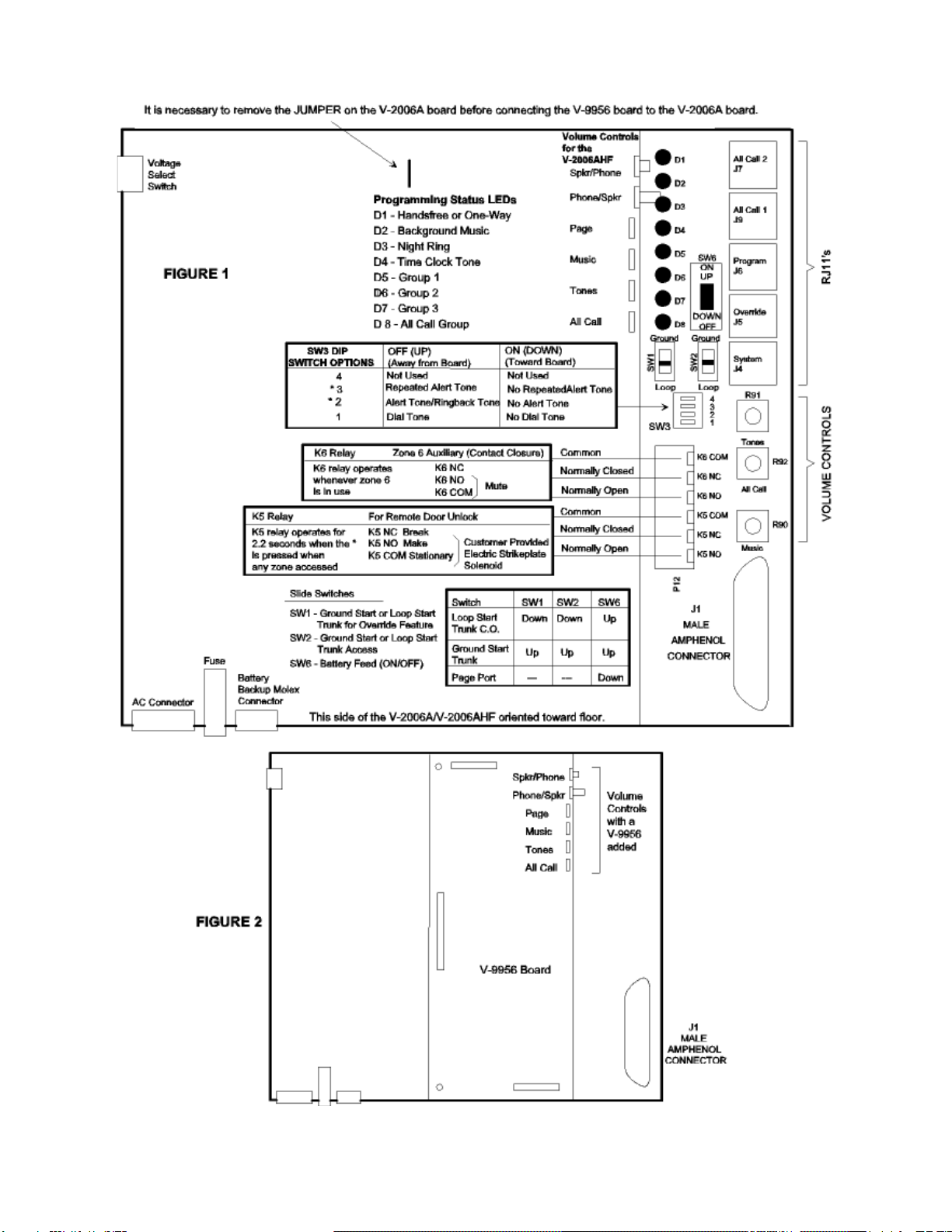
__ 10. Restore power to the V-2006A, access page
and adjust the volume controls as required.
There are separate volume controls for the
Phone to Speaker, Speaker to Phone, Page,
All Call, Background Music, and Tone
Signaling. For best results, the Speaker to
Phone volume control should be turned as
low as possible to where background music
is just barely audible.
__ 11. When using talkback speakers, the zone
must be programmed for talkback
communication. Refer to the V-2006A VSP
for programming instructions.
TECHNICAL ASSISTANCE
When trouble is reported, verify that power is being
supplied to the unit and there are no broken
connections. Check voltages for proper polarity on
the crossconnect block. If a spare unit is available,
substitute that unit for the suspected defective unit.
Assistance in troubleshooting is available from the
factory. When calling, you should have a VOM,
several clip leads, a telephone test set available and
be calling from the job site. Call (540) 427-3900 and
ask for Technical Support, or (540) 427-6000 for
Valcom 24-hour Automated Support or visit our
website at http://www.valcom.com.
The V-9956 contains no user serviceable parts and is
not field repairable. A service facility is maintained
in Roanoke, VA. Should repairs be necessary, attach
a tag to the unit clearly stating your company name,
address, phone number, contact person, and the
nature of the problem. Send the unit to:
Valcom, Inc.
Repair and Return Dept
5614 Hollins Road
Roanoke, VA 24019-5056
VALCOM LIMITED WARRANTY
Valcom, Inc. warrants its products to be free from defects in materials and workmanship under conditions of normal use and service
for a period of one year from the date of shipment. The obligation under this warranty shall be limited to the replacement, repair or
refund of any such defective device within the warranty period, provided that:
1. inspection by Valcom, Inc. indicates the validity of the claim,
2. the defect is not the result of damage, misuse, or negligence after the original shipment.
3. the product has not been altered in any way or repaired by others and that factorysealed units are unopened (A service
charge plus parts and labor will be applied to units defaced or physically damaged),
4. freight charges for the return of products to Valcom are prepaid,
5. all units ‘out of warranty’ are subject to a service charge. The service charge will cover minor repairs (Major repairs will be
subject to additional charges for parts and labor).
This warranty is in lieu of and excludes all other warranties, expressed or implied, and in no event shall Valcom, Inc. be
liable for any anticipated profits, consequential damages, loss of time or other losses incurred by the buyer in connection
with the purchase, operation, or use of the product.
This warrantyspecifically excludes damage incurred in shipment. In the event a product is received in damaged condition, the
carrier should be notified immediately. Claims for such damage should be filed with the carrier involved in accordance with the
F.O.B. point.
Headquarters: In Canada
Valcom, Inc. CMX Corporation
1111 Industry Avenue 35 Van Kirk Drive #11 and 12
Roanoke, VA 24013 Brampton, Ontario L7A1A5
Phone: (540) 427-3900 Phone: (905) 456-1072
FAX: (540) 427-3517 FAX: (905) 456-2269

3947208

4947208
26
1
27
2
28
3
29
4
30
5
31
6
32
7
33
8
34
9
35
10
36
11
37
12
38
13
39
14
40
15
41
16
42
17
43
18
44
19
45
20
46
21
47
22
48
23
49
24
50
25
W/BL
BL/W
W/O
O/W
W/GR
GR/W
W/BR
BR/W
W/S
S/W
R/BL
BL/R
R/O
O/R
R/G
G/R
R/BR
BR/R
R/S
S/R
BK/BL
BL/BK
BK/O
O/BK
BK/G
G/BK
BK/BR
BR/BK
BK/S
S/BK
Y/BL
BL/Y
Y/O
O/Y
Y/G
G/Y
Y/BR
BR/Y
Y/S
S/Y
V/BL
BL/V
V/O
O/V
V/G
G/V
V/BR
BR/V
V/S
S/V
ABC DEF
FIGURE 3
66 BLOCK CONNECTIONS FOR T E V-9956
System Tip
System Ring
Override Tip
Override Ring
Music Input
Music Input
Page Port Contact Closure
Inhibit
Zone 1 - Low Level Output Tip
Zone 1 - Low Level Output Ring
-24V out
GND Out
Zone 2 - Low Level Output Tip
Zone 2 - Low Level output Ring
-24V Out
GND Out
Zone 3 - Low Level Output Tip
Zone 3 - Low Level Output Ring
-24V Out
GND Out
Zone 4 - Low Level Output Tip
Zone 4 - Low Level Output Ring
-24V Out
GND Out
Zone 5 - Low Level Output Tip
Zone 5 - Low Level Output Ring
-24V Out
GND Out
Zone 6 - Low Level Output Tip
Zone 6 - Low Level Output Ring
-24V Out
GND Out
Zone 1 - andsfree Output Tip
Zone 1 - andsfree Output Ring
Zone 2 - andsfree Output Tip
Zone 2 - andsfree Output Ring
Zone 3 - andsfree Output Tip
Zone 3 - andsfree Output Ring
Zone 4 - andsfree Output Tip
Zone 4 - andsfree Output Ring
Zone 5 - andsfree Output Tip
Zone 5 - andsfree Output Ring
Zone 6 - andsfree Output Tip
Zone 6 - andsfree Output Ring
Clock Closure
Clock Closure
UNA Closure
UNA Closure
UNA Ringing
UNA Ringing
Used with the V-9956 Installed
Popular Automobile Accessories manuals by other brands

Thule
Thule 757 instructions

HAUL MASTER
HAUL MASTER 500 LB. CAPACITY KNOCKDOWN CARGO CARRIER Set up and operating instructions

Seizmik
Seizmik 90049 Installation & operation manual

Porsche
Porsche Wall Charger Connect OPERATING AND INSTALLATION Manual

Sharp
Sharp IG-DC2E Operation manual

Titan Ramps
Titan Ramps 120S owner's manual