Valcom IP FlexHorn VIP-580A User manual

1 947836
ISSUE 2
VIP-580A / VIP-581A
IP FlexHorn Surface Mount
INTRODUCTION
The VIP-580A and VIP-581A IP FlexHorn
Surface Mount units enable loudspeaker voice
paging anywhere on an Ethernet network. The
VIP-580A/VIP-581A consists of a network-
connected high efficiency horn, allowing stand
alone capability when used with a SIP telephone
system or can be accessed from a variety of
Valcom managed VoIP products. Power is
provided to the VIP-580A or VIP-581A via a
Power over Ethernet (PoE) switch meeting the
802.3af specification.
SPECIFICATIONS
Access Methods
SIP telephone system
PBX, FXO Port w/Valcom Network
Station Port
POTS telephone set w/Valcom Network
Station Port
PBX, FXS Port w/Valcom Network Trunk Port
Valcom M Cast Page Group
Features
Power over Ethernet (PoE) 802.3af
compatible
Angled surface mount (VIP-581A)
Straight surface mount (VIP-580A)
Paintable grille and enclosure
Nominal Power Requirements
Via 802.3af (PoE) Ethernet Switch: Class 3
Environment
Interior Installation only
Temperature: 0 to +40° C
Humidity: 0 to 85% non-precipitating
VIP-580A
VIP-581A
Dimensions/Weight
VIP-580A:
10.0” H x 12.2" W x 4.0" D
(25.4cm H x 30.9cm W x 10.2cm D)
Weight: 7.4 lbs. (3.4 kg)
VIP-581A:
9.9” H x 12.2" W x 4.0" D (top) x
2.7” D (bottom)
(25.2cm H x 30.9cm W x 10.2cm D (top) x
6.9cm D (bottom)
Weight: 7.4 lbs. (3.4 kg)

2
CAUTION: To reduce the risk of electric shock,
Do not remove cover.
No user serviceable parts inside.
Refer servicing to qualified service personnel.
CAUTION
RISK OF ELECTRIC SHOCK
DO NOT OPEN
This symbol indicates that dangerous
voltage constituting a risk of electric
shock is present within this unit.
This symbol indicates that there are
important operating and maintenance
instructions in the literature accompanying
this unit.
Precautionary Designations
FCC Information
This equipment has been tested and found to
comply with the limits for a Class A digital
device, pursuant to Part 15 of the FCC Rules.
These limits are designed to provide
reasonable protection against harmful
interference when the equipment is operated
in a commercial environment. This
equipment generates, uses, and can radiate
radio frequency energy and if not installed
and used in accordance with the instruction
manual, may cause harmful interference to
radio communications. Operation of this
equipment in a residential area may cause
harmful interference in which case the user
will be required to correct the interference at
his own expense.
INSTALLATION
Operation
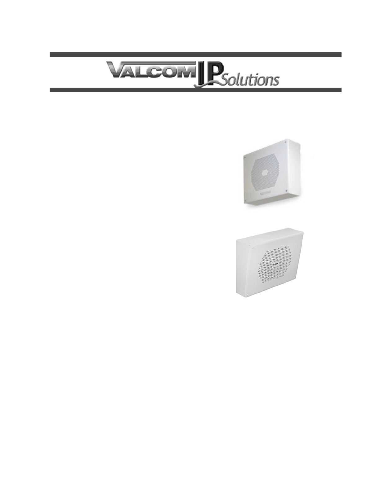
The VIP-580A/VIP-581A provides IP loudspeaker
paging access via network connection to
customer telephone system or stand alone
telephone set. Interface to customer telephone
system can be via SIP registration, FXO or FXS
port (with appropriate PBX connection and
Valcom Network Station Port or Trunk Port).
Mounting
The VIP-580A/VIP-581A is designed for surface
mounting on a solid surface. Remove the grille
from the backbox enclosure and disconnect the
FlexHorn wire harness from the network interface
board.
Pre-drilled 13/64” mounting holes in the back of
the enclosure are designed to fit a single gang,
double gang or octagon outlet box. If not
attaching to an outlet box, use the enclosure as a
template and mark the location of mounting
holes. Depending on wall construction type,
prepare the mounting hole locations on the wall
to securely attach the enclosure. Insert Ethernet
wiring through large hole in rear panel of
enclosure and connect to the Ethernet RJ-45
socket. Use mounting hardware (not included)
appropriate for the wall type to securely mount
the enclosure to the wall or outlet box. With the
enclosure securely mounted, reconnect the
FlexHorn wiring harness to the network interface
board and install the FlexHorn faceplate to the
enclosure using the four screws provided.
Figure 1.
Power Connections
The only method of powering a VIP-580A/
VIP-581A IP FlexHorn is via a Power over
Ethernet (PoE) network switch or power injector
meeting the 802.3af specification.
Network Connection
The VIP-580A/VIP-581A has one Ethernet RJ-45
network connector on the circuit board. Connect
an Ethernet patch cable from the network switch
to the VIP-580A/VIP-581A Ethernet RJ-45 socket
before attaching the grille to the enclosure.
Signal Connections
Signal connections from the network interface to
the FlexHorn are provided through an attached
wiring harness pre-wired at the factory. If the
horn was disconnected while mounting the
enclosure, reconnect the two-wire harness to
screw terminals labeled SPEAKER on the
network interface board before attaching the grille
to the enclosure.

3
Status Indicator Lights
The VIP-580A/VIP-581A Network Interface has 2
status indicator lights on the RJ-45 Ethernet
connector.
Green LED: (Link) Indicates Ethernet connection
when illuminated.
Yellow LED: (Activity) Indicator flashes to
indicate network activity.
Setup
Information specific to your application will need
to be programmed into the VIP-580A/VIP-581A
using a computer. The PC used for programming
should be connected to the same subnet as the
VIP-580A/VIP-581A. Setup will be done using
the IP Solutions Setup Tool. The IP Solutions
Setup Tool may be downloaded from the Valcom
web site at http://www.valcom.com.
TECHNICAL ASSISTANCE
Assistance in troubleshooting is available from
the factory. Call (540) 563-2000 and press 1 for
Technical Support or via email at
When requesting assistance, you should include
all available information. It is strongly suggested
that you go to the web site and follow the trouble
resolution procedure at http://www.valcom.com.
Valcom equipment is not field repairable.
Valcom, Inc. maintains service facilities in
Roanoke, VA. Should repairs be necessary,
attach a tag to the unit clearly stating your
company name, address, phone number, contact
person and the nature of the problem. Send the
unit to:
Valcom, Inc.
Repair & Return Dept.
5614 Hollins Road
Roanoke, Va. 24019-5056
VALCOM LIMITED WARRANTY
Valcom, Inc. warrants its products only to the original purchaser, for its own use, to be free from defects in materials and workmanship under conditions of
normal use and service for a period of one year from the date of shipment. This Limited Warranty obligation shall be limited to the replacement, repair or refund
of any such defective device within the warranty period, provided that:
1. inspection by Valcom, Inc. indicates the validity of the claim;
2. the defect is not the result of damage, misuse or negligence after the original shipment;
3. the product has not been altered in any way or repaired by others and that factory sealed units are unopened (a service charge plus parts
and labor will be applied to units defaced or physically damaged);
4. freight charges for the return of products to Valcom are prepaid;
5. all units 'out of warranty' are subject to a service charge. The service charge will cover minor repairs (major repairs will be subject to
additional charges for parts and labor).
This Limited Warranty is in lieu of and excludes all other warranties, expressed or implied and in no event shall Valcom, Inc. be liable for any
anticipated profits, consequential damages, loss of time or other losses incurred by the buyer in connection with the purchase, operation,
maintenance, installation, removal or use of the product. The maximum liability of Valcom under this warranty is limited to the purchase price of the
specific Product covered by the warranty.
Disclaimer. Except for the Limited Warranty provided herein, the product is provided “as-is” without any warranty of any kind whatsoever including, without
limitation, any WARRANTY OF MERCHANTABILITY, FITNESS FOR A PARTICULAR PURPOSE OR NON-INFRINGEMENT.
This warranty specifically excludes damage incurred in shipment. In the event a product is received in damaged condition, the carrier should be notified
immediately. Claims for such damage should be filed with the carrier involved in accordance with the F.O.B. point.
Headquarters:
Valcom, Inc.
5614 Hollins Road Roanoke, VA 24019-5056
Phone: (540) 563-2000 FAX: (540) 362-9800
This manual suits for next models
1
Table of contents