2 947556
CAUTION: To reduce the risk of electric shock,
Do not remove cover (or back).
No user serviceable parts inside.
Refer servicing to qualified service personnel.
This symbol indicates that dangerous
voltage constituting a risk of electric
shock is present within this unit.
This symbol indicates that there are
important operating and maintenance
instructions in the literature accompanying
FCC Information
This equipment has been tested and found
to comply with the limits for a Class A digital
device, pursuant to Part 15 of the FCC Rules.
These limits are designed to provide
reasonable protection against harmful
interference when the equipment is operated
in a commercial environment. This
equipment generates, uses and can radiate
radio frequency energy and if not installed
and used in accordance with the instruction
manual, may cause harmful interference to
radio communications. Operation of this
equipment in a residential area may cause
harmful interference in which case the user
will be required to correct the interference at
one’s own expense.
INSTALLATION
Mounting
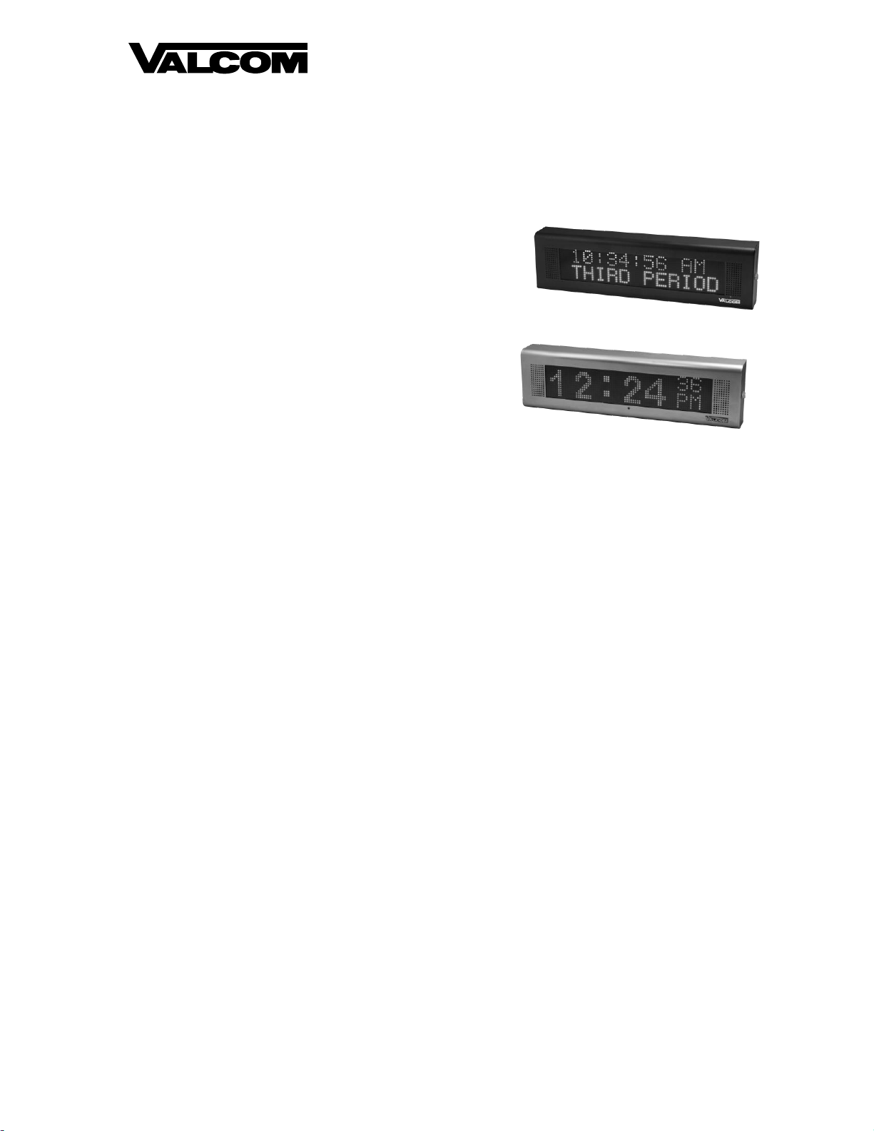
The VL520-IC message display should be
mounted with appropriate hardware (not
included). We recommend the mounting base
to be mounted into wall studs. (See Figure 2).
CONNECTIONS
Network Connection / Power
The VL520-IC has one RJ-45 network
connector. Connect a standard patch cable to
the VL520-IC from an Ethernet switch
supporting the Power over Ethernet
specification 802.3af (PoE) or 802.3at (PoE+).
If a PoE switch is not available, a mid-span
injector may be used to supply power to the
display, or an optional Valcom 24 Vdc power
adapter may be connected to the barrel
connector on the circuit board (see Figure 1).
The recommended power supply is a
VP-1124D.
Call Switch Connection
The VL520-IC provides a call switch input via
screw terminal connections labeled Switch 1.
(See Figure 1)
Relay Connection
One relay output is provided through three
screw terminals labled Normally Open (NO) and
Normally Closed (NC). The center screw
terminal is common to both NO and NC. The
relay contacts are rated 1 amp @ 24 Vdc.
Line Out Connection
The Line Out connection provides line level
output sufficient to drive up to 40 Valcom
self-amplified speakers.
IMPORTANT SAFETY INFORMATION
CONSIGNES DE SÉCURITÉ IMPORTANTES
1. Read these instructions.
Lisez ces instructions.
2. Keep these instructions.
Conservez ces instructions.
3. Heed all warnings.
Respectez tous les avertissements.
4. Follow all instructions.
Suivez toutes les instructions.
5. Do not use this apparatus near water.
Ne pas utiliser cet appareil près de l'eau.
6. Clean only with dry cloth.
Nettoyer avec un chiffon sec.
7. Do not block any ventilation openings. Install in accordance with the manufacturer’s
instructions.
Ne pas bloquer les ouvertures de ventilation. Installer formément aux instructions du
fabricant.
8. Do not install near any heat sources such as radiators, heat registers, stoves or other
apparatus (including amplifiers) that produce heat.
Ne pas installer à proximité de sources de chaleur telles que radiateurs, registres de
chaleur, poêles ou autres appareils (y compris les amplificateurs) produisant de la chaleur.
9. Do not defeat the safety purpose of the polarized or grounding-type plug. A polarized plug
has two blades with one wider than the other. A grounding type plug has two blades and a
third grounding prong. The wide blade and thethird prong are provided for your safety. If
the provided plug does not fit into your outlet consult an electrician for replacement of the
obsolete outlet.
Ne pas contourner le dispositif de sécurité de la fiche polarisée ou de mise à la terre. Une
fiche polarisée possède deux lames dont une plus large que l'autre. Une fiche de terre a
deux lames et une troisième broche de mise à la terre. La lame large et la troisième
broche sont fournies pour votre sécurité. Si la fiche fournie ne rentre pas dans votre prise,
veuillez consulter un électricien pour le remplacement de la prise obsolète.
10.Protect the power cord from being walked on or pinched particularly at plugs, convenience
receptacles and the point where they exit from the apparatus.
11.Only use attachments/accessories specified by the manufacturer.
N'utilisez que des fixations / accessoires spécifiés par le fabricant.
12. Use only with the cart, stand, tripod, bracket or table specified
by the manufacturer or sold with the apparatus. When a cart is
used, use caution when moving the cart/apparatus combination
to avoid injury from tip-over.
Utilisez uniquement avec le chariot, stand, trépied, support ou table spécifié par le
fabricant ou vendu avec l'appareil. Quand un chariot est utilisé, Soyez prudent lorsque
vous déplacez l'ensemble chariot / appareil pour éviter des blessures dues au
renversement.
13. Unplug this apparatus during lightning storms or when unused for a long period of time.
Débranchez cet appareil pendant les orages ou lorsqu'il n'est pas utilisé pendant une
longue période de temps.
14. Refer all servicing to qualified service personnel. Servicing is required when the
apparatus has been damaged in any way. Such as when the power supply cord or plug is
damaged, liquid has been spilled, objects have fallen into the apparatus or the
apparatus has been exposed to rain or moisture and does not operate normally or has
been dropped.
Confiez toute réparation à un personnel qualifié. Une réparation est nécessaire lorsque
l'appareil a été endommagé de quelque façon. Parexemple lorsque le cordon
d'alimentation ou la fiche est endommagé, du liquide a été renversé, si des objets sont
tombés dans l'appareil ou le appareil a été exposé à la pluie ou à l'humidité et ne
fonctionne pas normalement ou s'il est tombé.