Valcom V-2952 User manual
VSP-V-2952
Issue 4
1947952
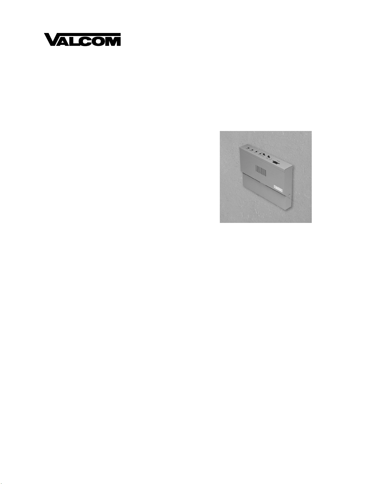
V-2952
FM TUNER
INTRODUCTION
The V-2952 FM Tuner may be used to provide a
music source for both background music for a paging
system and music-on-hold for a telephone system.
These instructions contain the specifications and
information necessary to install, operate, and maintain
the FM Tuner.
SPECIFICATIONS
Applications
•Valcom Paging Systems
•Stand Alone Background Music Systems
•Music-On-Hold
Features
•Two individual outputs each with volume control
a) Output 1: .5 watt
b) Output 2: Line level
•Separate bass and treble tone controls
•Frequency locked loop tuning system
•External antenna provided
•Internal speaker for monitoring
•On/Off switch
•Power on indicator
•Powered by –24 Vdc or –12 Vdc
•Power jack for use with receptacle mount power
supply
•Wall or shelf mount
•Local/Distant Signal reception switch
Options
•–12 Vdc power supply available (VP-412A)
Capacity
•V-2952 will drive one 8 Ohm or six 45 Ohm
speakers from the .5 watt output.
•V-2952 will drive up to 150 Valcom one-way
amplified speakers from the line output.
Dimensions/Weight
•6.19" H x 8.25" W x 1.55" D
(15.72cm H x 20.96cm W x 3.94cm D)
•1.3 lbs (.59kg)
Environment
•Temperature: 10 to 40 Degrees C
•Humidity: 0 to 85% non-precipitating
Performance (Nominal)
•Frequency tuning range:87.5 MHz to 108.5 MHz
•Power Output: .5 watt (at 8 ohms)
-10 dB (line out)
•S/N Ratio: -50dB
•Distortion: less than 2% @ rated output
Power Requirements
•Voltage: Power Input 1: –24 Vdc
Power Input 2: –12 Vdc
•Current: 250 mA

2947952
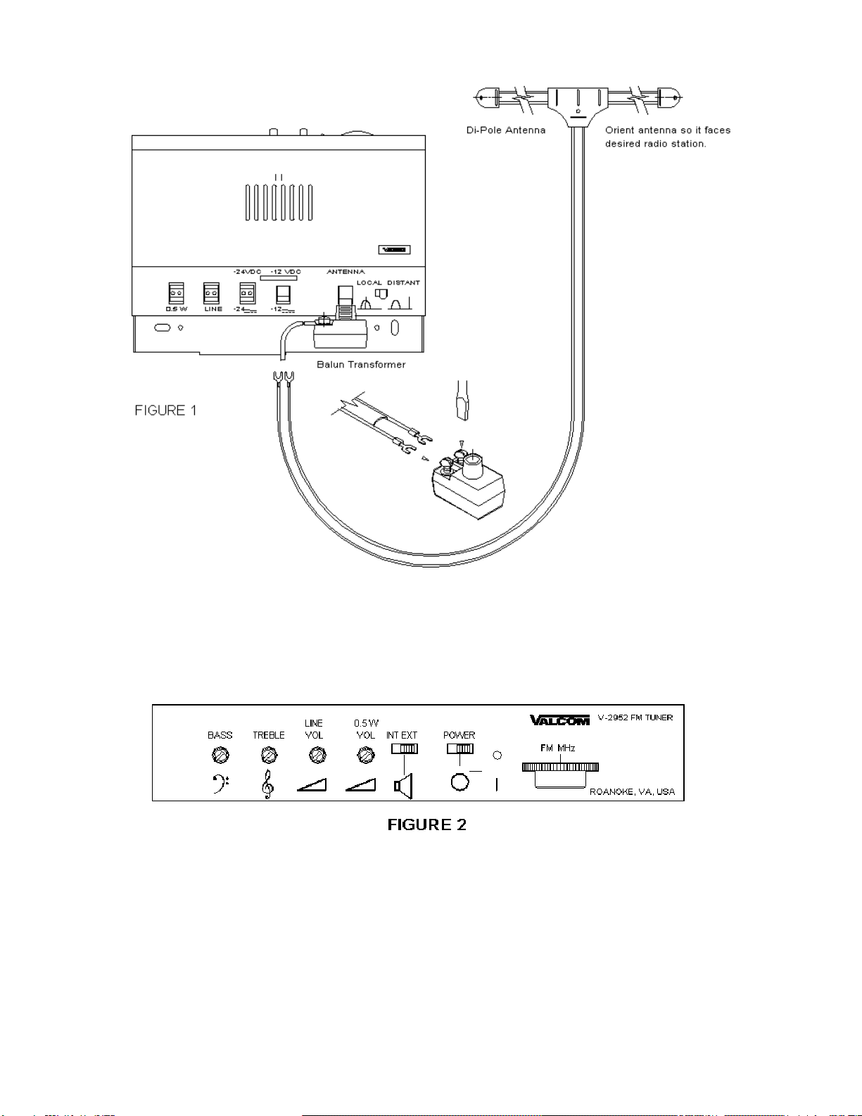
INSTALLATION
Connecting Arrangement
If a –12 Vdc power adapter is used, begin with Step
1. For power connections using a –24Vdc power
supply start at Step 2. (Refer to Figure 1)
__ 1. Plug –12 Vdc power adapter into receptacle
provided on the V-2952 (Go to Step 4).
__ 2. Connect –24 Vdc "-" from power supply to
one 24 Vdc terminal on the V-2952.
__ 3. Connect GND "+" from power supply to the
other 24 Vdc terminal on the V-2952.
NOTE: The –24 Vdc inputs are not polarity
sensitive.
__ 4. If the V-2952 is being connected to a
Valcom page control or amplified paging
speakers, connect the Output marked
"LINE" to the background music input of
the paging system or directly to the
dedicated speakers.
__ 5. When the V-2952 is connected to V-9941A,
connect the output marked "0.5 W" to the
music terminals of the V-9941A.
__ 6. If the V-2952 is connected to a telephone
system for music-on-hold, connect the
Output marked "0.5 W" to the music-on-
hold input of the telephone system.
__ 7. An external antenna is supplied. Install the
supplied balun transformer and dipole
antenna as shown in Figure 1 or connect a
customer supplied antenna with coax cable
to the "F" connector.
Setup Procedure
The setup procedure for the V-2952 is as follows
(Refer to Figure 2).
__ 1. With the power supply connected, turn
power switch "ON."
__ 2. Set EXT/INT switch to "INT."
__ 3. Rotate 0.5 W volume control ¼ turn
clockwise.
__ 4. Adjust tuning knob to desired FM station.
__ 5. Turn EXT/INT switch to "EXT" position
and adjust appropriate output volume control
to desired levels for background music or
music-on-hold. Adjust V-2952 Bass and
Treble controls to desired tone of music.
If distortion occurs due to close proximity of a strong
local station move the LOCAL/DISTANT switch to
the "LOCAL" position. (Refer to Figure 1)
TECHNICAL ASSISTANCE
Assistance in troubleshooting is available from the
factory. When calling, you should have a VOM and a
test set available and be calling from the job site. Call
(540) 427-3900 and ask for Technical Support, or call
(540) 427-6000 for Valcom 24-hour Automated
Support or visit our website at
http://www.valcom.com.
Valcom equipment is not field repairable. Valcom,
Inc. maintains service facilities in Roanoke, VA.
Should repairs be necessary, attach a tag to the unit
clearly stating your company name, address, phone
number, contact person, and the nature of the
problem. Send the unit to:
Valcom, Inc.
Repair and Return Dept.
5614 Hollins Road
Roanoke, VA 24019-5056
VALCOM LIMITED WARRANTY
Valcom, Inc. warrants its products to be free from defects in materials and workmanship under conditions of normal use and service for a
period of one year from the date of shipment. The obligation under this warranty shall be limited to the replacement, repair or refund of
any such defective device within the warrantyperiod, provided that:
1. inspection by Valcom, Inc. indicates the validity of the claim,
2. the defect is not the result of damage, misuse, or negligence after the original shipment,
3. the product has not been altered in any way or repaired by others and that factory sealed units are unopened (A service charge plus
parts and labor will be applied to units defaced or physically damaged)
4. freight charges for the return of products to Valcom are prepaid
5. all units 'out of warranty' are subject to a service charge. The service charge will cover minor repairs (Major repairs will be subject to
additional charges for parts and labor).
This warranty is in lieu of and excludes all other warranties, expressed or implied, and in no event shall Valcom, Inc. be liable for
any anticipated profits, consequential damages, loss of time or other losses incurred by the buyer in connection with the
purchase, operation or use of the product.
This warrantyspecifically excludes damage incurred in shipment. In the event a product is received in damaged condition, the carrier
should be notified immediately. Claims for such damage should be filed with the carrier involved in accordance with the F.O.B. point.
Headquarters:
Valcom, Inc.
1111 Industry Avenue
Roanoke, VA 24013
Phone: (540) 427-3900
FAX: (540) 427-3517
In Canada:
CMX Corporation
35 Van Kirk Drive #11 and 12
Brampton, Ontario L7A1A5
Phone: (905) 456-1072
FAX: (905) 456-2269
3947952
Other Valcom Tuner manuals


Popular Tuner manuals by other brands


MFJ
MFJ MFJ-928 instruction manual

NAD
NAD C 445 owner's manual

Sony
Sony ST-SA5ES operating instructions

Sirius Satellite Radio
Sirius Satellite Radio SC-FM1 user guide

Antique Automobile Radio
Antique Automobile Radio 283501B Installation and operating instructions

Monacor
Monacor PA-1200R instruction manual


