Valex PE1810 User manual

PE1810
S420715
29.11.2016
Final dimension: A5
ATTENZIONE! Prima di usare la macchina, leggete attentamente le istruzioni di sicurezza e d’uso
CAUTION! Before starting the machine, carefully read the safety and operating instructions
Pialla elettrica per legno
ISTRUZIONI D’USO
Istruzioni originali
Electric wood planer
OPERATING INSTRUCTIONS
Translation of the original instructions

- 2 -

- 3 -

- 4 -
DATI TECNICI
1. Tensione e frequenza nominale
2. Potenza nominale assorbita
3. Giri tamburo portalame
4. Profondità di taglio regolabile
5. Dimensione lame
6. Peso netto
7. Classe isolamento macchina
8. Pressione acustica
9. Potenza acustica
10.Vibrazioni
TECHNICAL DATA
1. Voltage and nominal frequency
2. Absorbed nominal power
3. Blade-holder drum revolutions
4. Adjustable depth of the cut
5. Blade dimensions
6. Net Weight
7. Machine insulation class
8. Acoustic pressure
9. Acoustic power
10.Vibrations
1 230V~50 Hz
2 750 W
3 nO16500 min-1
4 0-3 mm
5 82x6,8x1,2 mm
6 2,6 kg
7 II
8 91,3 dB(A) K=3
9 102,3 dB(A) K=3
10 6,593 m/s2K=1,5
DICHIARAZIONE DI CONFORMITA’
La ditta indicata in etichetta dichiara sotto la
propria responsabilità che il prodotto ivi citato
è conforme ai requisiti essenziali di sicurezza
e salute contenuti nelle seguenti direttive euro-
pee: 2006/42/CE, 2014/35/CE, 2014/30/CE,
2011/65/CE
DECLARATION OF CONFORMITY
The firm indicated on the label declares, under
its own responsibility, that the product cited
there complies with the essential health and
safety requirements contained in the following
European directives:
2006/42/EC, 2014/35/EC,
2014/30/EC, 2011/65/EC
Valex S.p.A. - Schio (VI) - ITALY
11.2016
Un procuratore - Attorney
SMIDERLE STEFANO

- 5 -
i
Vi ringraziamo per averci preferito nella scelta di que-
sto utensile elettrico, di seguito chiamato piallatrice.
ATTENZIONE! La piallatrice è idonea a spia-
nare superfici di legno. Ogni altro uso è vietato.
Questo istruzioni riportano le informazioni e
quanto ritenuto necessario per il buon uso, la co-
noscenza e la normale manutenzione dell’utensile.
Esse non riportano le informazioni sulle tecniche
di lavorazione del legno; l’utilizzatore troverà mag-
giori notizie su libri e pubblicazioni specifiche o
partecipando a corsi di specializzazione.
ATTENZIONE! Prima di usare il prodotto per la
prima volta, leggete ed applicate le istruzioni
per l’uso e le prescrizioni di sicurezza allegate
al fine di evitare pericoli e operazioni scorrette.
Ogni altro uso diverso da quello espressamente
indicato può arrecare gravi danni a persone o
animali e deve ritenersi improprio ed espressa-
mente vietato, oltre a far decadere la garanzia
offerta dal produttore.
Conservate con cura tutta questi documenti per
la consultazione durante tutta la vita del prodotto.
COMPONENTI
Fare riferimento alla fig.A e seguenti:
1. Interruttore avvio/arresto
2. Dispositivo di sicurezza antiavviamento
3. Impugnatura posteriore
4. Impugnatura anteriore/ regolatore di profondità
5. Pulsante di sblocco regolatore di profondità
6. Piano di appoggio
7. Guida per smussare gli angoli
8. Guida laterale
9. Squadretta di supporto
10. Volantino o vite fissaggio guida laterale
11. Volantino o vite fissaggio squadretta
12. Scarico trucioli
13. Dispositivo per appoggio dell’utensile
14. Feritoie di ventilazione motore
15. Guida di profondità
16. Volantino fissaggio guida di profondità
17. Protezione mobile
18. Lama
19. Tamburo portalama
20. Piastrina portalama
21. Blocchetto portalama
22. Grani filettati per regolazione allineamento lama
23. Viti fissaggio lama
24. Spina e cavo di alimentazione
25. Sacchetto raccoglitrucioli
SIMBOLOGIA
Osservate con attenzione la simbologia della
fig.B e memorizzate il rispettivo significato. Una
corretta interpretazione dei simboli consente un
uso più sicuro della macchina.
1 Modello
2 Dati tecnici
3 Marchio di certificazione
4 Numero di lotto
5 Doppio isolamento elettrico
6 I rifiuti elettrici ed elettronici possono conte-
nere sostanze pericolose per l’ambiente e per
la salute umana; non devono pertanto essere
smaltiti con quelli domestici ma mediante
una raccolta separata negli appositi centri di
raccolta o riconsegnati al venditore nel caso di
acquisto di una apparecchiatura nuova analoga.
Lo smaltimento abusivo dei rifiuti comporta
l’applicazione di sanzioni amministrative
7 Attenzione!
8 Leggete con attenzione tutte le istruzioni
prima dell’uso
9 Indossare guanti a protezione delle mani.
10 Indossare occhiali a protezione degli occhi,
cuffie antirumore.
11 Indossare una maschera a protezione delle
vie respiratorie.
V Volt
Hz Hertz
~ corrente alternata
A Ampere
W Watt
kg chilogrammi
mm millimetri
s secondi
h ore
dB decibel

- 6 -
INSTALLAZIONE
ATTENZIONE! La Ditta costruttrice declina
ogni responsabilità per gli eventuali danni
diretti e/o indiretti causati da un errato al-
lacciamento.
ATTENZIONE! Prima di effettuare le se-
guenti operazioni assicuratevi che la spina
sia scollegata dalla presa di alimentazione
elettrica.
ATTENZIONE! Indossate guanti a protezio-
ne delle mani.
TRASPORTO
Per trasportare l’utensile utilizzate sempre il suo
imballo o la sua valigetta (se presente); questo lo
preserverà da urti, polvere e umidità che ne pos-
sono compromettere il regolare funzionamento.
MOVIMENTAZIONE
Afferrate saldamente l’impugnatura (pos.3)
senza azionare l’interruttore, mantenete l’utensile
lontano dal vostro corpo e dopo l’uso appoggia-
telo senza battere.
MESSA IN SERVIZIO
Nel luogo che utilizzerete l’utensile elettrico è
opportuno considerare:
- che la zona non sia umida e sia al riparo dagli
agenti atmosferici.
- che attorno sia prevista un’ampia zona opera-
tiva libera da impedimenti.
- che vi sia una buona illuminazione.
- che sia utilizzata in vicinanza dell’interruttore
generale con differenziale.
- che l’impianto di alimentazione sia dotato di
messa a terra conforme alle norme (solo se
l’utensile elettrico è di classe I, cioè dotato di
spina con cavo di terra).
- che la temperatura ambiente sia compresa tra 10°
e 35° C.
- che l’ambiente non sia in atmosfera infiammabile/
esplosiva.
Estraete la macchina ed i componenti e verificate
visivamente la loro perfetta integrità; a questo
punto procedete ad una accurata pulizia.
MONTAGGIO GUIDA LATERALE (pos.8)
La guida laterale è necessaria quando il pezzo ha
un lato perpendicolare alla superficie da piallare.
Assemblate le pos.8-9-10-11 come illustrato in
fig.A e serrate bene i volantini.
MONTAGGIO GUIDA DI PROFONDITÀ (pos.15)
La guida di profondità è utile per l’esecuzione
di piallatura a gradino, da regolare in base alla
profondità da ottenere.
Assemblate le pos.15-16 come illustrato in fig.A
e serrate bene il volantino.
DISPOSITIVO DI APPOGGIO (pos.13)
Il dispositivo di appoggio serve quando dovete
appoggiare l’utensile e fare in modo che le lame
non tocchino la superficie.
MONTAGGIO SACCO RACCOGLITRUCIOLI
(pos.25)
Il sacco raccoglitrucioli deve essere applicato al
raccordo scarico trucioli (pos.12) e serve solo
per lavori di breve durata.
COLLEGAMENTO AD UN ASPIRATORE ELET-
TRICO (non incluso)
E’ obbligatorio collegare il raccordo di scarico
trucioli (pos.12) ad un aspiratore elettrico,
mediante una tubazione flessibile non metallica;
in questo modo gran parte dei trucioli e della
polvere prodotta verranno evacuati.
AVVIAMENTO ED ARRESTO
ATTENZIONE! Prima di avviare l’utensile
elettrico è obbligatorio indossare i dispositivi
di protezione individuale citati nel cap. Avver-
tenze (non inclusi).
ATTENZIONE! Prima dell’avviamento e
durante la fase di lavoro, afferrare saldamente
l’utensile con entrambe le mani nelle impu-
gnature senza mai abbandonare la presa, in
modo tale che, in caso di pericolo, possiate
arrestarla immediatamente.
ATTENZIONE! Durante l’utilizzo fate in
modo che nessuno si avvicini alla vostra zona
di lavoro.
Collegate la spina dell’utensile (pos.24) alla
presa di alimentazione elettrica.
Avviamento ed arresto
Interruttore con dispositivo di sicurezza:
- per avviare azionate in sequenza il dispositivo
di sicurezza (pos.2) e poi premete l’interruttore
“ON - I” (pos.1).
- per arrestare rilasciate l’interruttore “OFF – O”
mantenendo ben saldo l’utensile.
L’interruttore è del tipo ad “azione mantenuta”;

- 7 -
pertanto l’utensile elettrico rimarrà acceso per il
tempo che voi mantenete premuto l’interruttore.
Vi consigliamo di ripetere queste operazioni
alcune volte prima di iniziare il lavoro in modo
da familiarizzare il più possibile con i comandi.
Se osservate delle anomalie di funzionamento
spegnete l’utensile elettrico e consultate il capitolo
“Problemi, cause e rimedi”.
Quando non lavorate spegnete e staccate la
spina dalla presa.
ISTRUZIONI D’USO
Dopo aver letto attentamente i capitoli prece-
denti, seguite scrupolosamente questi consigli
che vi permetteranno di ottenere il massimo
delle prestazioni.
Procedete con calma in modo da prendere
familiarità con tutti i comandi; solo dopo aver
acquisito una buona esperienza riuscirete a
sfruttarne a fondo tutte le potenzialità.
LAME
Acquistate lame di qualità, con dimensioni indi-
cate nei dati tecnici dell’utensile e adatte al legno
da lavorare; rivolgetevi al vostro rivenditore di
fiducia che potrà consigliarvi al meglio. La nostra
azienda produce un’ampia gamma di accessori
adatti ai più svariati impieghi.
Le lame durante l’uso si usurano, perdono l’affilatu-
ra, si danneggiano, si rompono: effettuate sempre
un controllo visivo prima dell’uso e se necessario
sostituitele. Rammentate che la finitura del pezzo
dipende anche dalle condizioni delle lame.
Per montaggio e sostituzione vedere il capitolo
“MANUTENZIONE – Sostituzione lame”.
Maneggiate e conservate con cura le lame, non
esponendole a urti, flessione, compressione,
umidità; proteggetele dalla corrosione con olio.
USO
ATTENZIONE! E’ vietato l’utilizzo dell’uten-
sile con una sola mano.
Indossate i dispositivi di protezione individuale
elencati nel cap. Avvertenze.
Il pezzo in lavorazione deve essere sempre salda-
mente fissato al banco di lavoro, con una morsa
o altro, specialmente con i pezzi piccoli e leggeri.
È possibile regolare la profondità di passata pre-
mendo il pulsante di sblocco (pos.5) ruotando
il volantino (pos.4).
Questa deve essere predeterminata in base alla
finitura superficiale che vorrete ottenere, alla
durezza del legno, alla larghezza del pezzo, alla
velocità di avanzamento. Osservate la tabella
seguente ed effettuate delle prove su pezzi scarti:
Lavorazione Condizioni d’uso Risultato
Sgrossatura - Profondità di
passata alta
- Velocità di avan-
zamento alta
- Superficie grosso-
lana “a onde”
- Sollecitazioni ec-
cessive all’utensile
e alle lame
Finitura - Profondità di
passata bassa
- Velocità di avan-
zamento bassa
- Superficie liscia
Per i legni duri o/e pezzi larghi effettuare solo sottili
asportazioni di materiale con avanzamenti lenti.
Impugnate l’utensile con entrambe le mani. Il
cavo di alimentazione deve essere tenuto lontano
dalle parti rotanti e dal vostro corpo.
Avviate l’utensile mantenendolo lontano dal vo-
stro corpo. Quando acceso movimentatelo con
prudenza, in quanto una disattenzione potrebbe
causarvi ferite anche gravi; perciò mantenete
lontano dalla zona di lavoro gli estranei, i bambini
e gli animali. Per nessun motivo mettere le mani
sotto l’utensile.
La normale posizione dell’operatore è con brac-
cia leggermente distese in avanti, con l’utensile
che lavora davanti a voi; mantenete le gambe
leggermente divaricate ed assumente una po-
sizione stabile senza sbilanciarvi.
L’utensile deve essere avviato prima di entrare
a contatto con il pezzo, in caso contrario è
possibile che subiate un contraccolpo a causa
dell’incastrarsi della lama nel pezzo.
A seconda del tipo di lavorazione operate sul
pezzo con attenzione e procedete gradualmente
senza forzare troppo nell’azione. Una pressione
eccessiva sul pezzo potrebbe causare la rot-
tura delle lame; inoltre l’utensile elettrico sarà
sollecitato maggiormente e la sua durata sarà
breve fino al mancato funzionamento. Durante
l’avanzamento non sollevate e non inclinate
lateralmente l’utensile.
Evitate di avvicinare il viso alla zona di lavoro
e mantenete sempre una certa distanza di
sicurezza.
PIALLATURA IN PIANO
Per effettuare spianature e riduzioni di spessore
di travi, listelli ecc.

- 8 -
Appoggiate la parte anteriore dell’utensile
(pos.6) alla parte iniziale del pezzo di legno e,
con utensile in funzione, avanzate sulla superfi-
cie del pezzo esercitando una leggera pressione
su di esso.
Vi consigliamo di non sostare con l’utensile
sul pezzo e di non interrompere la lavorazione,
che deve essere eseguita dall’inizio alla fine del
pezzo; in caso contrario si produrranno degli
avvallamenti non voluti.
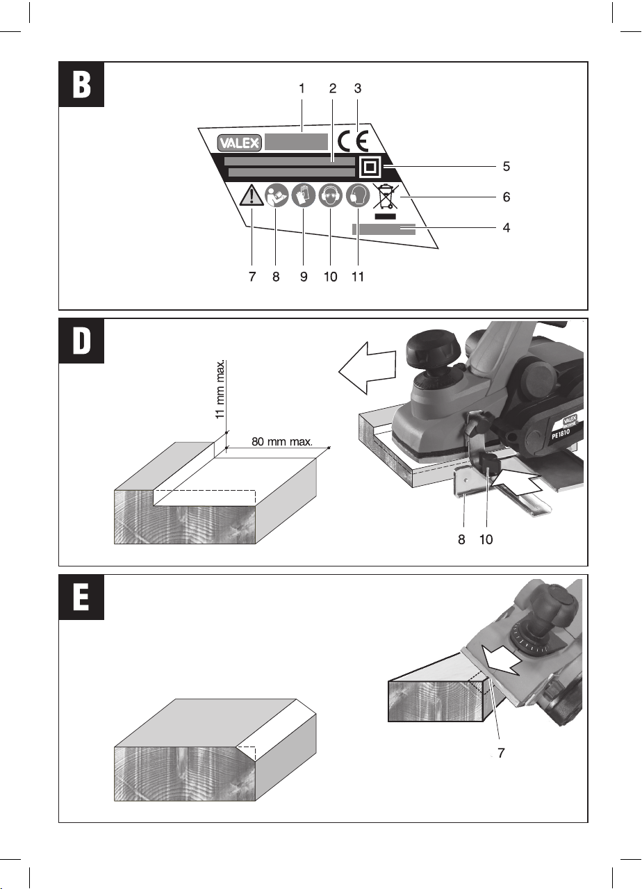
PIALLATURA CON GUIDA LATERALE (fig.D)
Per effettuare una sagomatura a gradino.
ATTENZIONE! Per la regolazione della gui-
da laterale è necessario operare con le mani
in prossimità delle lame; scollegate perciò la
spina dall’alimentazione elettrica ed indossate
guanti di protezione.
Regolate la guida laterale (pos.8) per una lar-
ghezza desiderata e serrate il volantino (pos.10).
Regolate la guida di profondità (pos.15) per
un’altezza desiderata e serrate il volantino
(pos.16).
Appoggiate la parte anteriore dell’utensile
(pos.6) alla parte iniziale del pezzo di legno e,
con utensile in funzione, avanzate sulla superfi-
cie del pezzo esercitando una leggera pressione
su di esso.
Effettuate più passate, in modo da raggiungere
l’altezza del gradino desiderata. La profondità
massima che potrete eseguire è in funzione
della protezione laterale destra dell’utensile e,
quando il pezzo la toccherà, non è più possibile
effettuare ulteriori passate.
Vi consigliamo di non sostare con l’utensile
sul pezzo e di non interrompere la lavorazione,
che deve essere eseguita dall’inizio alla fine del
pezzo; in caso contrario si produrranno degli
avvallamenti non voluti.
PIALLATURA A 45° (fig.E)
Per effettuare lo smusso di uno spigolo.
ATTENZIONE! Questa lavorazione espone
le parti rotanti e le lame, perciò prestate
maggiore attenzione a movimentare le mani
e l’utensile.
Si consiglia di effettuare questa operazione su
superfici già lavorate e perpendicolari tra di loro.
Inclinate l’utensile di 45° ed appoggiate la parte
anteriore dell’utensile (pos.6) sul pezzo in corri-
spondenza della scanalatura a V (pos.7) e, con
utensile in funzione, avanzate lungo lo spigolo
del pezzo (nel senso di lunghezza) esercitando
una leggera pressione su di esso. Se necessario
effettuate più passate per togliere altro materiale.
Al termine spegnete l’utensile, attendete l’arresto
completo, appoggiatelo al banco e staccate l’ali-
mentazione elettrica. Non arrestare la rotazione
contro il pezzo, ma attendere l’arresto prima di
posare l’utensile.
MANUTENZIONE
ATTENZIONE! Prima di ogni controllo o
regolazione scollegate la spina dalla presa di
alimentazione elettrica.
ATTENZIONE! Non manomettete o tentate
di riparare l’utensile elettrico.
ATTENZIONE! Una eventuale revisione inter-
na, la sostituzione della cinghia di trasmissione o
la sostituzione delle spazzole in grafite del motore
che si usurano con l’uso, deve essere effettuata
solamente da un centro assistenza autorizzato.
La durata e il costo d’esercizio dipendono anche
da una costante e scrupolosa manutenzione.
Pulite regolarmente ed abbiate cura del vostro
utensile elettrico, vi garantirete una perfetta
efficienza ed una lunga durata dello stesso.
- Rimuovete la polvere e i residui di lavorazione
con uno straccio e un pennello a setole morbide.
- Non spruzzate o bagnate d’acqua l’utensile
elettrico, pericolo di infiltrazioni interne.
- Non usate infiammabili, detergenti o solventi vari.
- Le parti in plastica sono aggredibili da agenti
chimici.
- Non utilizzate un getto d’aria compressa per la
pulizia: pericolo lancio materiale!
- Prestate particolare attenzione alla pulizia
dell’interruttore, alle feritoie di ventilazione del
motore, alle impugnature.
SOSTITUZIONE DELLE LAME DI TAGLIO (fig.A)
Le lame hanno due lati taglienti e sono quindi
utilizzabili nei due lati; quando una lama non
taglia più in maniera corretta, è possibile girare
la lama dal lato opposto (2° tagliente). Quando
entrambi i due lati saranno usurati, è necessario
sostituire le lame.
Effettuate le seguenti operazioni su entrambe le
lame montate sul tamburo.
Smontaggio e rimontaggio lame
Prima di procedere osservate attentamente i
componenti dell’utensile, il verso di montaggio

- 9 -
del tagliente lama e la fig.A. Se non avete dime-
stichezza con la manipolazione e l’assemblaggio
di componenti meccanici, vi consigliamo di
rivolgervi ad un centro assistenza autorizzato.
1) Indossate i guanti a protezione delle mani.
2) Scollegate la spina dalla presa di alimen-
tazione elettrica.
3) Con una chiave avvitate a fondo le viti
(pos.23), poste nel blocchetto portalama
(pos.21). Attenzione: la sede ricavata nel
tamburo per l’alloggiamento del blocchetto
portalama è a sezione trapezoidale e ciò
impedisce l’estrazione del blocchetto por-
talama.
4) Sollevare da un lato il blocchetto portalama
e sfilare la lama (pos.18), aiutandosi ad
esempio con un cacciavite piatto, senza
togliere tutto il blocchetto dal tamburo. Fate
attenzione alla direzione di taglio della lama
così da rimontarla poi correttamente.
5) Come noterete, la lama ha due lati taglienti.
Tra i due lati delle lame è ricavata una sca-
nalatura che funge da guida.
6) Pulire tutti i componenti e la sede nel
tamburo.
7) Inserite la nuova lama (o la stessa lama
girata nel 2° tagliente) nella piastrina porta-
lama (pos.20), ed entrambe nel blocchetto
portalama.
8) Rimettete il blocchetto portalama completo
in sede e fissate poco le due viti esterne
(pos.23). Fate attenzione che i fianchi esterni
del blocchetto siano centrati rispetto alla lar-
ghezza del tamburo (non devono sporgere).
9) Occorre ora effettuare l’allineamento delle
lame. Se non si sono mossi i grani filettati
(pos.22), la lama dovrebbe essere già in
posizione ottimale; è però da effettuare
sempre l’allineamento della lama rispetto il
piano di appoggio.
10) Ruotate il tamburo lentamente in modo da
portare la lama nella posizione di massima
altezza rispetto il piano di appoggio.
11) Regolare a zero il piano di appoggio tramite
il pomello (pos.5).
12) Appoggiate ora una riga metallica o una
squadra sul piano di appoggio; in questo
modo verificate l’allineamento lama. Veri-
ficare l’allineamento in più punti (esempio
dal lato destro al lato sinistro dell’utensile).
La regolazione ottimale si ottiene quando la
lama tocca appena la riga o quadretta. Nel
caso la lama non fosse allineata, avvitare o
svitare i grani filettati.
13) Assicurare bene la lama svitando tutte le viti
(pos.23) in modo che spingano contro i fian-
chi della sede del tamburo e premano la lama.
14) Effettuare ora le operazioni sopra descritte
per la seconda lama, dato che il tamburo è
provvisto di due lame.
15) Verificare il corretto assemblaggio dei
componenti e il serraggio delle viti (pos.23).
16) Effettuare una prova di funzionamento a
vuoto per 1 minuto, mantenendo l’utensile
lontano da voi.
PROBLEMI, CAUSE E RIMEDI
PROBLEMA CAUSE RIMEDI
L’utensile
elettrico
non si avvia
Linea di alimenta-
zione scollegata Verificate la linea
di alimentazione
elettrica
Spina non inserita Inserire la spina
nella presa di ali-
mentazione elet-
trica e premere il
pulsante di avvio
Interruttore in po-
sizione di spento
OFF “O”
Azionare l’interrut-
tore in posizione di
acceso ON “I”
Spazzole motore
usurate Rivolgetevi ad un
centro di assisten-
za autorizzato
Guasto elettrico Rivolgetevi ad un
centro di assisten-
za autorizzato
L’utensile
elettrico
vibra molto
Lame danneggiate
o senza tagliente Sostituire le lame
Lame montate in
modo errato Smontare le lame,
pulire i componen-
ti e rimontare se-
guendo le istruzioni
Durante la
lavorazione
le lame si
arrestano
ma l’utensi-
le continua
a funzionare
Cinghia di trasmis-
sione usurata o rotta Rivolgetevi ad un
centro di assisten-
za autorizzato
Superficie
del pezzo
con finitura
scadente
Lame danneggiate o
senza tagliente Sostituire le lame
Profondità di passa-
ta troppo alta Ridurre la profondi-
tà di passata
Velocità di avanza-
mento troppo rapida Ridurre la velocità
di avanzamento
ATTENZIONE! Se dopo aver eseguito gli in-
terventi sopra descritti l’utensile elettrico non

- 10 -
funziona correttamente o in caso di anomalie
diverse da quelle indicate, portatelo presso un
centro di assistenza autorizzato esibendo la
prova di acquisto e richiedendo ricambi origi-
nali. Fate sempre riferimento alle informazioni
riportate sull’etichetta dati tecnici.
IMMAGAZZINAMENTO
Effettuate una accurata pulizia di tutta la mac-
china e sue parti accessorie (vedi paragrafo
Manutenzione). Proteggete le parti metalliche
non verniciate con un olio protettivo ed utilizzate
l’imballo originale o la valigetta (se presente) per
proteggerla.
Riponete la macchina lontano dalla portata dei
bambini, in posizione stabile e sicura. Il luogo
dovrà essere asciutto, privo da polveri, tempe-
rato e protetto dai raggi solari diretti.
Al locale di rimessaggio non devono avere
accesso i bambini e gli estranei.
SMALTIMENTO
Per la salvaguardia ambientale procedete se-
condo le leggi vigenti del Paese in cui vi trovate.
Rivolgetevi alle autorità competenti per maggiori
notizie in merito.
Quando la macchina non è più utilizzabile né
riparabile, consegnatela con l’imballo ad un
punto di raccolta per il riciclaggio.
I rifiuti elettrici ed elettronici possono con-
tenere sostanze pericolose per l’ambiente e
la salute umana; non devono pertanto essere
smaltiti con quelli domestici ma mediante
una raccolta separata negli appositi centri di
raccolta o riconsegnati al venditore nel caso
di acquisto di una apparecchiatura nuova
analoga. Lo smaltimento abusivo dei rifiuti
comporta l’applicazione di sanzioni ammi-
nistrative.
GARANZIA
Il prodotto è tutelato a norma di legge contro non
conformità rispetto alle caratteristiche dichiarate
purché sia stato utilizzato esclusivamente nel
modo descritto dalle istruzioni, non sia stato
manomesso in alcun modo, sia stato conser-
vato correttamente, sia stato riparato da tecnici
autorizzati e, ove previsto, siano stati utilizzati
solo ricambi originali.
In caso di utilizzo industriale o professionale
oppure in caso di impiego simile la garanzia ha
validità di 12 mesi.
Per emettere una richiesta di intervento in garan-
zia è necessario presentare la prova di acquisto
al rivenditore o ad centro assistenza autorizzato.

- 11 -
g
We thank you for having purchased this electrical
tool that will hereafter also be referred to as “planer”.
IMPORTANT! The planer is suitable for planing
wooden surfaces. Any other use is prohibited.
These instructions contain information deemed
necessary for proper use, knowledge and stan-
dard appliance maintenance. They do not include
information on wood processing techniques; the
user can find additional information in specific
books or publications or by attending special
training courses.
WARNING! Before using the product for the
first time, read and apply the enclosed instruc-
tions for use and safety requirements in order
to avoid danger and incorrect operations.
Any other use other than that expressly indi-
cated may cause serious damage to persons
or animals and should be considered improper
and expressly prohibited, as well as voiding the
warranty offered by the manufacturer.
Carefully kept all these documents for consulta-
tion throughout the life of the product.
COMPONENTS
Refer to fig. A and the following figures:
1. Start/stop switch
2. Safety immobiliser device
3. Rear hand grip
4. Front hand grip/ depth regulator
5. Depth adjuster release button
6. Support surface
7. Guide for bevelling edges
8. Side guide
9. Support bracket
10. Wheel or screw for fixing side guide
11. Wheel or screw fixing bracket
12. Sawdust discharge
13. Device for placing the tool
14. Engine air vents
15. Depth guide
16. Wheel for fixing the depth guide
17. Mobile guard
18. Blade
19. Blade-holder drum
20. Blade-holder plate
21. Blade-holder block
22. Grub screws for adjusting blade alignment
23. Blade fixing screws
24. Power supply plug and cable
25. Sawdust bag
SYMBOLS
Carefully observe the symbols in fig.B and
memorise their respective meanings. Correct
interpretation of the symbols allows a safer use
of the machine.
1 Model
2 Technical data
3 Certifications
4 Production batch number
5 Double electric insulation
6 Electric and electronic waste may contain
potentially hazardous substances for the
environment and human health. It should
therefore not be disposed of with dome-
stic waste, but by means of differentiated
collection at specific centres or returned to
the vendor in the event of purchasing a new
identical power tool. The illegal disposal of
waste will result in administrative sanctions
7 Warning!
8 Carefully read the instructions before use
9 Wear protective gloves
10 Wear safety goggles to protect your eyes,
and safety earmuffs
11 Wear a mask to protect your respiratory tract
V Volt
Hz Hertz
~ alternating current
A Ampere
W Watt
kg kilograms
mm millimetres
s seconds
h hours
dB decibel

- 12 -
INSTALLATION
IMPORTANT! The manufacturer is not
liable for any direct and/or indirect damage
caused by incorrect connections.
IMPORTANT! Before you perform the
following steps, make sure that the plug is
disconnected from the AC power supply.
IMPORTANT! Wear protective gloves.
TRANSPORT
Always use the packaging or case (when provi-
ded) when transporting the tool; this will protect
it from impact, dust and humidity which can
compromise normal operation.
HANDLING
Firmly grasp the hand grip (pos.3) without using
the switch; keep the tool well away from your
body and after use place it down gently.
SWITCHING ON
When choosing where to use the power tool, the
following should be considered:
- that the place is not damp and is protected from
the weather.
- that there is a large operational area free from
obstructions.
- that there is good lighting.
- that it needs to be used close to the general
differential switch.
- that the power supply system is earthed and
conforms to the standards (only if the power
tool is class 1, which is equipped with a plug
with earth cable).
- that the room temperature is between 10° and
35 °C.
- that the environment is not in a flammable/
explosive atmosphere.
Take out the machine and its components and
visually check that they are perfectly intact; then
proceed to thoroughly clean them.
SIDE GUIDE ASSEMBLY (pos.8)
The side guide is needed when the workpiece
has a side perpendicular to the surface that is to
be planed. Assemble pos.8-9-10-11 as shown
in fig.A and tighten the wheels well.
DEPTH GUIDE ASSEMBLY (pos.15)
The depth guide is useful for carrying out rebate
planing, to be adjusted according to the depth
to be obtained.
Assemble pos.15-16 as shown in fig.A and
tighten the wheel well.
SUPPORTING DEVICE (pos.13)
The supporting device is needed when you must
put the tool down so as that the blades do not
touch the surface.
SAWDUST BAG ASSEMBLY (pos.25)
The sawdust bag must be attached to the
sawdust discharge connector (pos.12) and can
be used for short jobs only.
CONNECTING TO AN ELECTRICAL VACUUM
CLEANER (not included)
It is obligatory to connect the sawdust discharge
connector (pos.12) to an electrical vacuum cle-
aner, via a flexible, non-metallic tube; by doing
this much of the sawdust and dust produced
will be cleared out.
SWITCHING ON AND OFF
IMPORTANT! Before switching on the
electrical tool it is mandatory to wear personal
protection equipment (not provided) listed in
the chapter Warnings.
IMPORTANT! Before starting the tool and
during operation, hold the tool firmly with both
hands, using both handgrips, without ever
letting go, so that you can stop the machine
immediately in the case of danger.
IMPORTANT! Make sure nobody is ap-
proaching the working area while the tool is
running.
Plug the tool (pos.24) into the electricity supply.
Starting and stopping the device
Switch with safety device:
- to start, in sequence press the safety device
(pos. 2) and then press the “ON - I” (pos. 1)
switch.
- to switch off, release the “OFF – O”
switch, holding the tool firmly.
The switch is a ‘maintained action’ switch so
the electrical tool will stay on when you keep
the switch pressed.
We recommend repeating these operations
several times before starting work, in order to
familiarise yourself with the controls as much
as possible.

- 13 -
If you notice any working defects, switch off the
power tool and consult the chapter “Problems,
causes and solutions”.
When not using the tool, turn it off and discon-
nect the plug from the socket.
USER INSTRUCTIONS
After reading the previous chapters carefully,
apply these tips scrupulously to obtain maximum
performance.
Proceed calmly so as to become familiar with
all the controls; after having gained sufficient
experience, you will be able to make full use of
its capacities.
BLADES
Buy quality blades, in the sizes indicated in the
tool’s technical details and change them accor-
ding to the wood to be worked; contact your local
dealer who will be able to best advise you. Our
company produces a wide range of accessories
suitable for various uses.
During use, the blades become worn, lose their
sharpness, become damaged and break: always
perform a visual check before using and replace
if necessary. Remember that the finish of the
workpiece also depends on the blades condition.
For the assembly and replacement, see the
chapter “MAINTENANCE- Blade replacement”.
Handle and store the blades with care; do not
expose them to impact, bending, compression,
moisture; protect them from corrosion with oil.
USE
IMPORTANT! It is forbidden to use the tool
with only one hand.
Wear the personal protective equipment listed
in the “Warnings” chapter.
The piece you are working on must always be
firmly secured to the workbench, using a vice or
other device, especially when working on small,
lightweight pieces.
It is possible to adjust the depth by pressing the
release button (pos.5) and by turning the knob
(pos.4). This must be predetermined by the
surface finish you wish to obtain, the hardness
of the wood, the width of the workpiece and the
moving speed. Look at the table below and carry
out tests on scrap pieces.
Processing Conditions of use Result
Coarse
planing - Elevated stroke
depth
- Elevated moving
speed
- Coarse “waved”
surface
- Excessive stress on
the tool and blades
Finish - Shallow stroke
depth
- Slow moving
speed
- Smooth surface
For hard woods and/or large workpieces, work
slowly removing only small amounts of material.
Hold the device with both hands. The power
cord must be kept far from the rotating parts
and from your body.
Start the tool, keeping it far away from your
body. When the tool is turned on, handle with
caution, as any carelessness may cause even
serious injury; therefore keep unauthorised
persons, children and pets away from the work
area. Under no circumstances put your hands
under the tool.
The normal position for the user is with arms
slightly stretched forward, with the functioning
tool in front of you; keep your legs slightly apart
and keep a stable position without losing your
balance.
The tool must be started before coming into
contact with the workpiece, otherwise you may
undergo a kickback because the blade gets stuck
in the workpiece.
Depending on the type of process, perform on
the part carefully and proceed gradually without
making forceful movements. Excessive pressure
on the workpiece could cause the blades to bre-
ak; in addition, the power tool will be put under
even more strain and it will not have a long life
span and will stop functioning. While guiding
the tool forward, do not lift it and do not tilt it
from side to side.
Avoid getting your face too close to the work
area and always keep a certain safety distance.
FLAT PLANING
To carry out flattening and to reduce the
thickness of beams, slats, etc.
Rest the front part of the tool (pos.6) on the first
part of the wooden workpiece and, with the tool
running, move the tool forward over the surface
of the workpiece, pressing down slightly on it.
We recommend that you do not pause with the
tool on the workpiece or interrupt the machining,
which should be carried out from the beginning

- 14 -
to the end of the workpiece; otherwise it will
produce some unwanted hollows.
PLANING WITH THE SIDE GUIDE (fig.D)
To carry out rebate shaping.
IMPORTANT! To adjust the side guide you
must work with your hands close to the blades;
therefore unplug the tool from the electrical
supply and wear protective gloves.
Adjust the side guide (pos.8) to the desired width
and tighten the wheel (pos.10).
Adjust the depth guide (pos.15) to the desired
depth and tighten the wheel (pos.16).
Rest the front part of the tool (pos.6) on the first
part of the wooden workpiece and, with the tool
running, move the tool forward over the surface
of the workpiece, pressing down slightly on it.
Make several strokes, so as to achieve the desi-
red depth of the rebate. The maximum depth that
can be achieved is based on the right side guard
of the tool and, when the workpiece touches it, it
will not be possible to carry out further strokes.
We recommend that you do not pause with the
tool on the workpiece or interrupt the machining,
which should be carried out from the beginning
to the end of the workpiece; otherwise it will
produce some unwanted hollows.
PLANING AT 45° (fig.E)
To bevel an edge
IMPORTANT! This process exposes the
rotating parts and blades, therefore pay
great attention when moving your hands and
the tool.
We recommend carrying out this process on
surfaces that have already been processed and
are perpendicular to one another.
Incline the tool to 45° and place the front part of
the tool (pos.6) on the workpiece at the V groove
(pos.7) and, with the tool running, move the tool
along the corner of the workpiece (lengthways),
applying slight pressure on it. If required, make
more strokes to remove more material.
Once you have finished, switch the tool off, wait
for it to stop completely, lay it on the bench and
unplug it. Do not switch off the device while it
is rotating against the part; wait for it to stop
rotating before placing it down.
MAINTENANCE
IMPORTANT! Before any checks or
adjustments unplug the tool from the electric
power supply.
IMPORTANT! Do not tamper or attempt to
repair the power tool.
IMPORTANT! Any internal service or repla-
cement of the drive belt or the motor’s graphite
brushes, which wear with use, must be carried
out exclusively by an authorised service centre.
The working life and costs also depend on con-
stant and meticulous maintenance.
Take good care of your power tool and clean it
regularly. In this way its efficiency will be ensured
and its lifespan extended.
- Remove dust and machining residuals with a
cloth or a brush with soft bristles.
- Do not wet or spray water over the power tool
- risk of internal infiltrations.
- Do not use any flammables, detergents or
solvents.
- The plastic parts can easily be damaged by
chemical agents.
- Do not use compressed air for cleaning: Risk
of material ejection!
- Be careful when cleaning the switch, motor fan
slots and handgrips.
REPLACING THE CUTTING BLADES (fig.A)
The blades have two cutting sides and can
therefore be used on both sides; when a blade
no longer cuts correctly, it can be turned to the
opposite side (2nd cutting edge). When both
sides are worn, the blades must be replaced.
Carry out the following tasks on both the blades
mounted on the drum.
Blade disassembly and reassembly
Before proceeding, closely observe the com-
ponents of the tool, the assembly direction of
blade’s cutting edge and fig.A. If you are not fa-
miliar with handling and assembling mechanical
components, we recommend that you consult
an authorised service centre.
1) Wear protective gloves.
2) Unplug the machine from the power supply.
3) Fully tighten the screws with a wrench
(pos.23), located in the blade-holder block
(pos.21). Caution! the recess in the drum
made to accommodate the blade-holder
block is trapezoidal and therefore prevents
the extraction of the blade-holder block.

- 15 -
4) Lift the blade-holder block on one side and
take the blade (pos.18), using a tool to help
you, such as a flat headed screwdriver,
without removing the whole block from the
drum. Make note of the cutting direction
of the blade so that you can reassemble it
correctly.
5) As you will see, the blade has two cutting
sides. Between the two sides of the blade
there is a groove that acts as a guide.
6) Clean all the components and the drum
recess.
7) Insert the new blade (or the same blade
turned to the 2nd cutting edge) in the blade-
holder plate (pos.20), and both in the blade-
holder block.
8) Return the complete blade-holder block into
place and tighten the two external screws
slightly (pos.23). Make sure that the outer
sides of the block are in a central position
in respect to the drum’s width (they should
not protrude).
9) It is now necessary to align the blades. If
the grub screws have moved (pos.22), the
blade may already be in the perfect position;
however blade alignment should always be
carried out in respect to the support surface.
10) Slowly turn the drum so as to bring the
blade into the position of maximum height
in respect to the support surface.
11) Adjust the support surface to zero via the
knob (pos.5).
12) Now place a metal ruler or set square on the
support surface; in this way you can check
the blade alignment. Check the alignment at
several points (for example from the right
to left side of the tool). Perfect adjustment
is achieved when the blade just touches the
ruler or set square. If the blade is not aligned,
tighten or loosen the grub screws.
13) Secure the blade well by loosening all the
screws (pos.23) so that they push against
the sides of the drum recess and press the
blade.
14) Now repeat the instructions described
above for the second blade, as the drum
has two blades.
15) Check the correct assembly of the com-
ponents and the tightening of the screws
(pos.23).
16) Perform a dry run for 1 minute, keeping
the tool away from your body.
PROBLEMS, CAUSES AND SOLUTIONS
PROBLEMS CAUSES SOLUTIONS
The power
tool does
not start
Power supply line
disconnected Check the electric
power supply line
Plug not inserted Insert the plug in
the electric power
supply socket and
press the start
button
Switch in the OFF
“O” position Switch in the ON
“I” position
Worn motor
brushes Contact an authori-
sed service centre
Electrical fault Contact an authori-
sed service centre
The power
tool vibrates
heavily
Dull or damaged
blades Replace the blades
Incorrectly assem-
bled blades Remove the bla-
des, clean the
components and
reassemble fol-
lowing the instruc-
tions
During ma-
chining the
blades stop
but the tool
continues to
run
Worn or broken dri-
ve belt Contact an authori-
sed service centre
Surface of
the workpie-
ce has a
poor finish
Dull or damaged
blades Replace the blades
Surface stroke
depth too high Reduce stroke
depth
Moving speed too
high Reduce moving
speed
IMPORTANT! If the power tool still fails
to operate correctly after you have carried
out the above operations, or in the event of
anomalies other than those described above,
take it to an authorised service centre with
proof of purchase and ask for original spare
parts. Always refer to the information shown
on the technical specifications label.
STORAGE
Clean the machine and all its accessories tho-
roughly (see Maintenance section). Protect the
unpainted metal parts with protective oil and use
the original packaging or case (where fitted) to
protect it.

Store the machine in a stable and safe position
out of children’s reach. The place must be dry,
free from dust, temperate and protected from
direct sunlight.
Keep children and unauthorised personnel out
of the storage room.
DISPOSAL
In order to protect the environment, proceed
according to the local laws in force. Contact the
relevant authorities for more information.
When the machine is no longer usable or repai-
rable, take the machine and its packaging to a
recycling centre.
Electric and electronic waste may contain
potentially hazardous substances for the en-
vironment and human health: they should not,
therefore, be disposed of along with domestic
waste but be taken to specific centres for dif-
ferentiated refuse collection or returned to the
vendor in the event of purchasing a new, identical
appliance. The illegal disposal of waste will result
in administrative sanctions.
WARRANTY
The product is protected by law against all non-
conformities with regard to its stated characte-
ristics, provided that it has been used solely in
the way described in this user’s instructions, it
has not been tampered with in any way, it has
been stored correctly, it has been repaired by
authorised personnel and, where necessary, only
original spare parts have been used.
In the event of industrial or professional use
or similar, the warranty is valid for 12 months.
To issue a request for intervention covered by
warranty, proof of purchase must be shown to
the retailer or authorised service centre.
Table of contents
Languages: