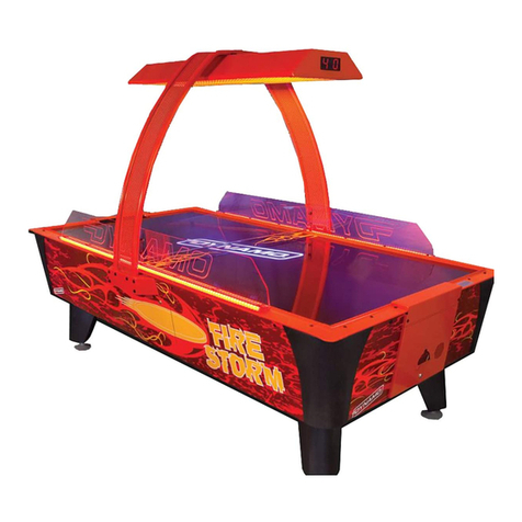
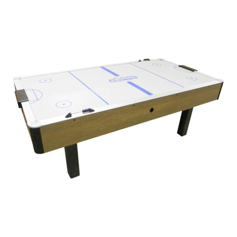
Valley-Dynamo Black Hole User manual


1

2
3 –Warranty
6 –Declaration of Conformity
6 –Warnings and notices
7 –Assembly instructions
13 –Overhead instructions
17 –Side Shield Installation
18 –Black Hole Programming
20 –Electronics Layout
23 –Selected Parts Listing
24 - Rules of Play
26 –Routine Maintenance
28 –Closing Notes

3
Valley-Dynamo warrants its new products to be free from defects resulting
from faulty manufacture or faulty components under the following terms and
conditions:
WARRANTY LENGTH
One year on Dynamo® Hockey tables. 90 days on Replacement Parts
FOR WARRANTY SERVICE
Valley-Dynamo will, at its sole option, repair, upgrade or replace this
product in the event of any defect in materials or workmanship during the
warranty period. This shall be Valley-Dynamo's sole obligation, and the
customer's sole remedy, for any warranty claim.
Valley-Dynamo will request and you must provide the complete Model
Number & Serial Number of the unit located inside the Black Hole’s CPU
ACCESS Door, or other proof of purchase such as an invoice or receipt.
OPERATORS AND END USERS –While our Tech Support staff is available
to assist with diagnosis and troubleshooting of your problem, contact your
Distributor for Warranty Service on your equipment.
DEALERS AND DISTRIBUTORS –To obtain replacement and an RMA
number, contact Valley-Dynamo referencing the Model number and Serial
number of the unit and the nature of the problem. Valley-Dynamo will, at its
discretion, send replacement parts and/or issue an RMA for the return of
failed parts. To avoid billing issues, request an RMA when the failed part is
present or readily available. Credit will be issued only upon receipt and
inspection of the RMA. Valley-Dynamo may send replacement parts or issue

4
an account credit. NO REFUNDS. Valley-Dynamo reserves the right to cancel
outstanding RMAs 30 days after issue. Items returned with no RMA will not be
inspected or credited and may be refused or returned at Customer Expense.
REPLACEMENT PARTS COVERAGE –Valley-Dynamo warrants
replacement parts for 90 days from the date of purchase. To obtain a
replacement and an RMA number, contact Valley-Dynamo referencing the
nature of the problem and provide proof of purchase. Valley-Dynamo will, at
its discretion, send replacement parts and/or issue an RMA for the return of
failed parts. To avoid billing issues, request an RMA when the failed part is
present or readily available. Upon receipt and inspection of the RMA,
Valley-Dynamo may send replacement parts or issue an account credit. NO
REFUNDS. Valley-Dynamo reserves the right to cancel outstanding RMAs 30
days after issue. Items returned without an RMA will not be inspected or
credited and may be refused or returned at Customer Expense.
SCOPE OF COVERAGE
Note that our warranty is not an unconditional guarantee for the duration.
Dynamo products are made to our exacting standards and known for their
durability, but are not indestructible and may require periodic maintenance
in order to function properly. The following are not covered by the warranty.
1)Shipping or transport damage
2)Normal wear and tear
3)Damage or deterioration resulting from neglect, misuse, accident, liquid
spills, improper installation, abuse, pets, burns, power surge or mishandling
Hockey Playfields - The most frequent cause of warpage or laminate separation on a
playfield is a liquid spill. Liquid spills are not a covered warranty failure. If warranty failure
is suspected, for evaluation Valley-Dynamo will require return of the damaged playfield or
at minimum at least 12 square feet (4’ x 3’) of the damaged section. No credit will be issued
for a Playfield damaged by a liquid spill, or for incoming or outgoing freight for the
replacement or returned playfield.
4) Incidental or consequential damage (except at Valley-Dynamo’s
discretion).
5) Removal or installation charges.
6) Shipping charges except at Valley-Dynamo’s discretion.
7) Unauthorized modification of the product.
8) Use of this product with unapproved parts, conversion kits or accessories.
9) Damage from fire, flood, lightning or other acts of nature

5
EXCLUSION OF DAMAGES
Valley-Dynamo’s sole obligation and liability under this warranty is limited
to the repair or replacement of a defective product at our option. Valley-
Dynamo shall not, in any event, be liable for any incidental or consequential
damages resulting from interruption of service, loss of business or revenue,
or for liability in tort relating to this product or resulting from its use or
possession.
LIMITATIONS OF IMPLIED WARRANTIES
There are no other warranties, expressed or implied, including but not
limited to those of merchantability, revenue generation, or fitness for a
particular purpose. The duration of implied warranties is limited to the
period specified in the Warranty Length section above.
TO OBTAIN TECHNICAL SUPPORT
Please check the resources available at www.valleydynamoparts.com or
contact TECHHELP@valley-dynamo.com.

6
USE OF NON-DYNAMO PARTS OR CIRCUIT MODIFICATIONS MAY CAUSE SERIOUS
INJURY OR EQUIPMENT DAMAGE! USE ONLY GENUINE DYNAMO AUTHORIZED PARTS.
For safety and reliability, substitute parts and modifications are not recommended.
Substitute parts or modifications may void FCC type acceptance.
Use only authorized components and parts. Failure to do so will void warranty and may
result in incorrect and/or unsafe operation.
WARNING
Plug this game into a properly grounded outlet to prevent shock hazards and assure
proper game operation.
Do not use an adapter plug to defeat the power cord's grounding pin.
Do not cut off ground pin.
Information in this manual is subject to change without notice. Dynamo reserves the right
to make improvements in the equipment function, design or components as process in the
engineering or manufacturing methods may warrant.
FOR GENUINE DYNAMO PARTS AND SERVICE CONTACT YOUR AUTHORIZED
DYNAMO DISTRIBUTOR.
PARTS CAN ALSO BE ORDERED AT WWW.VALLEYDYNAMOPARTS.COM

7
Congratulations on purchasing a Dynamo Hockey table -
the finest professional grade hockey table on the market.
BE SAFE: it is strongly recommended that you have at least two people for the safe
setup of our hockey tables.
The keys to open the coin and service doors are found with the
instruction manual, taped to the playfield protective pad.
Lay the box flat on the floor, mindful of the section labeled "This Side Up." Cut the
banding straps and remove the top portion of the box completely. Lower the sides of the
box bottom by carefully cutting or tearing vertically at all of the corners. Remove all
staples from the box top and bottom, retain the box top as it will be used later.
Note that we will refer to the COIN DOOR END of the table as
the BLUE and HOME end.
The EXTERIOR SERVICE DOOR is located on the end opposite
the coin door, also referred to as the RED or VISITOR end.
Open this door and remove the parts kits.
Recommended tools:
Drill
Ratchet
12” extension
½” Socket
½” open-end wrench
Adjustable wrench
Band cutters
Wire Cutters
Phillips Screw Driver
Rubber Mallet

8
Parts Kits
1x CAMERA BRACKET WITH CAMERAS
Game Play Pack
2 860400210 mallets
2 860400090 pucks
2 980400200 sand paper disks
Wire Harnesses
1 730409010 main overhead tube harness
1 Overhead AC harness
1 Power Cord
Overhead Diffusers
2 800404905 Diffuser expanded metal
screens
2 800404910 Bracket Diffuser
Leg Hardware kit
4x 870000124 8-32 x 5/8 screws
4x 870046103 Washer # 10
12x 870007390 5/16 bolts
12x 800404935 spacers
12x 870050106 Washers
4x 20300110 5/16 nuts
4x 870401000 Leg Levelers
We posted a video on the
ValleyDynamoTV YouTube page
to demonstrate hard-to-describe
postions of the assembly
process. Search YouTube.com
for ValleyDynamoTV, or you can
scan the QR code at right to go
directly to the video.
For best results, have the
manual handy AND the video

9
Note four attachment bolts at center,
light bulbs to either side in
protective cardboard.
Removal of the Overhead Display Unit.
The hockey table should now be carefully lifted onto its side (the end with the coin door
will be to your left, the end with the service door to your right). Have two people tilt the
table from the ends, do not lift from one side. The table could land on you and cause
injury if you lose your grip while lifting the table from its side.
With the table on its side, you can see the four 5/16” bolts securing the Overhead Display
Unit to the underside of the table. Use the ratchet, 12” extension and ½” socket, take care
not to damage the fluorescent light bulbs in the fixture, and remove the four bolts to free
the Overhead Display Unit. Carefully store the Overhead Display Unit for later use. The
attachment bolts will not be needed again.
Set the table back down, still
using the box bottom as a base.

10
The Secondary Box contains four overhead tubes (two male, two female) and two U-
shaped Legs. Slide the U-shaped legs under the central opening, opposing each other in
this manner as shown in the photo below, with the leg leveler openings facing up.
Note in the photo detail each leg has THREE
mounting holes, and the side of the table has
THREE corresponding holes. Each leg also has a
Wiring Access Hole corresponding to the square
hole in the cabinet.
At this point in the assembly process, use only the
lowest hole in the table and the lowest hole in the
leg. This is the pivot point for the legs.
While pulling the leg away
from the table side,
carefully slide one bushing
between the leg and the
table side wall. Insert one
5/16” leg mounting bolt and
washer through the leg and thread it into the
lowest leg mounting hole on the table’s side wall.
Pressure from the leg will hold the bearing tightly to the table’s side wall, so take care
when moving the table or adjusting the leg position to avoid damage to the side decal.
Turn the bolt by hand two or three turns to secure the leg but AGAIN DO NOT FULLY
TIGHTEN THE BOLT. Repeat the process with the same holes on the opposite side of this
leg. Then attach the table’s right leg in the same manner, remaining careful of the side
wall decal, and hand tightening the bolts 2 or 3 turns.
Once both legs have been attached at all four
points and may fully hand tighten all four leg bolts
but DO NOT FULLY TIGHTEN THEM UNTIL THE
OVERHEAD HAS BEEN INSTALLED, have two
people lift the table back onto its side: coin door
end to the left, service access door end to the
right. CPU ACCESS DOOR to the upper left, FAN
DOOR to the lower left.
CPU
Door
Fan
Door

11
Wiring
Access
Position the box top saved from unpacking the table on the floor, near the legs.
Now, rotate the legs so the two other bolt holes
from the photo line up with the corresponding
holes in the table. The legs should be at roughly
a 45-degree angle to the table, with the leg
leveler openings should be parallel to the
bottom of the table and flat to the floor. Install
the four leg levelers.
Use a #106 key to open the CPU ACCESS DOOR
(see photo) on the bottom surface of the table.
Take the Overhead Wire Harness from the Parts
Kit. Feed the end marked “TABLE SIDE / A” into
the leg closest to the CPU Access Door and into
the table using the Wiring Access Hole in the leg
and cabinet.
From the CPU Access Door, pull the Overhead
Wire Harness into the table cavity.
Plug two USB Connectors
into the Motherboard
Ports as shown to the left
(either connector can
plug into either USB port
on the motherboard)
Then connect the HDMI
video to the Motherboard
Port as shown to the right.
Last, plug the white 4-pin
and 6-pin connectors to
the available open
connections in the CPU
Access panel

12
At this point in the assembly process, use the center
hole in the table and the leg.
Pull the leg away from the table
and slide one bushing between
the leg and the table side wall.
Take care when installing the
bushing to keep from
damaging the side decal. Insert
one 5/16” leg mounting bolt
and washer through the leg and thread it into the
upper leg mounting hole on the table’s side wall.
Repeat this process for the other leg, then tilt the
table to where the bolts just inserted face down and
the other side of the table faces up. The CPU
ACCESS DOOR should now be to the lower right, and
FAN DOOR should be to the upper right.
Use a #106 key to open the FAN DOOR (see photos)
on the bottom surface of the table.
Take the Overhead AC Harness from the Parts Kit.
Feed the end marked “TABLE SIDE / B” into the leg
closest to the Fan Door and into the table using the
Wiring Access Hole in the leg and cabinet.
Now repeat the process for attaching the leg to the
table using the center hole in the leg and table.
Place one bushing between the leg and the table side
wall. Take care when installing the bushing to keep
from damaging the side decal. Slide one 5/16” leg
mounting bolt and washer through the leg and thread
it into the upper leg mounting hole on the table’s side
wall. MAKE SURE ALL 8 BOLTS ARE SNUG BUT DO
NOT FULLY TIGHTEN THE LEG BOLTS YET –YOU
WILL DO THAT ONCE THE UPPER OVERHEAD TUBES
ARE FULLY INSTALLED.
You may now set the table upright on its legs..

13
Installing the Overhead Mounting Tubes. Keep the wire harnesses accessible as they
will need to be fed into the overhead mounting tubes and plugged into the Overhead
Display Unit.
FIRST : route the Overhead Wire Harness through a FEMALE mounting tube. There is a
cut-out at the top of the tube for the wiring, Slide the female tube onto the lower U-shaped
leg.
SECOND : on the opposite side of the table, route the Overhead AC Harness through a
MALE mounting tube. Slide the male tube onto the lower U-shaped leg and assemble the
tops of the tubes, taking care that the wire
harnesses are accessible and have not been
crimped.
The hole under the tube should be parallel to the
playfield.

14
NOTE ALIGNMENT OF OVERHEAD MOUNTING TUBES
THIRD : Install Female and Male overhead mounting
tubes on opposite sides of the table as used on the
first two, use the diagram above as your guide.
Now, all four mounting tubes should be installed on
the table, with the wire harness accessible.
Install the third mounting bolt in
each of the four legs to secure the
overhead mounting tubes to the
legs. As with the first eight leg
bolts, use the bushings and take
care to prevent the bushing from
damaging the side decal.
The overhead bracket will have
THREE bolts installed to secure it.
Align the bracket so the corner
WITHOUT the bolt corresponds to
the overhead mounting tube
containing the Overhead Wire
Harness (note diagram above).
Tap the bracket with the rubber
mallet to install it atop the Overhead
Mounting Tubes.
Continue to watch that the wire harnesses
are not pinched, crimped or otherwise
restrained during the assembly process.
Service Door
Red/Visitor
End
No bolt
Coin Door
Blue/Home
End

15
Installing the Overhead Display Unit
Use care during this step, dropping the
overhead onto the playfield will almost
certainly damage the playfield and render
the game unplayable. If the table is in the
normal, upright position, we recommend
having TWO people to support Overhead
Display Unit for installation while a third
person secures the overhead with nuts and
washers. DROPPING AN OVERHEAD ONTO
A PLAYFIELD IS NOT A COVERED
WARRANTY DEFECT.
We also suggest removing the overhead
bulbs during installation, or using a 12”
extension to reach the bolts, but still leaving
the protective cardboard on the fluorescent
bulbs.
One end of the overhead will have a
Directional Indicator marker. THAT END OF
THE OVERHEAD SHOULD BE ORIENTED
TOWARD THE COIN DOOR END OF YOUR
BLACK HOLE TABLE.
Feed the Overhead AC Harness and Overhead Wire
Harness through the rectangular cut out. Then, secure
the four nuts and washers attaching the overhead with
the ½” socket (and the 12” extension).
Connect the Overhead Wire Harness HDMI cable to
the Splitter Input Connection, and the 6, 4 and 3 pin
connectors to their corresponding plugs in the
overhead.
At this point you may remove
the protective cardboard
from the Fluorescent Lamps,
or reinstall the lamps if you
removed them for safety
while attaching the Overhead
Display Unit.

16
Installing the Overhead Display Unit Camera Bracket
On either side of the Camera Bracket are three mounting tables. Slide the three tabs
on one side of the camera bracket into the groove located inside the Overhead Display
Unit. Next, pull out on the Overhead Display Unit wall closest to you to slip the three
tabs on the other side of the Camera Bracket (as in “the side now closest to you that is
not already anchored in a groove”) into the groove.
You may now connect the USB
Extension harness into the marked
camera connections,
Plug in the game and test for power up
and functionality. As with a computer,
“gibberish displays” can result if the
video cables are not fully connected.
For any display problems, ALWAYS
CHECK YOUR CONNECTIONS.
Install the safety diffuser grating and
locking brackets on the Overhead
Display Unit, fully tighten all leg bolts,
and secure all service doors.

17
Dynamo’s 3-piece Shield set will help to keep the puck on the
table and discourage the placement of drinks on the table’s side
rails. While it will create a safer environment, no shield has been
invented that will keep every puck on every playfield every time.
Exercise caution during play, keep hands and fingers clear of the
playfield, and follow the instructions from Dynamo Caution Label,
part # 850404030
Kit Contents:
Side Shields 2
Center Shield 1
Rubber Grommets 18
10-32 x 1½” Black Oxide Hex Bolts 4
Lock nuts 4
#10 Black Oxide Washers 8
Tool required
Phillips Screwdriver
1. Remove the bolts from the Side Top Rail, except for the bolt at the very
end of each Rail.
2. Insert Rubber Grommets into the holes from the top of each Side
Shield
3. Mount with the flange of the Shields to the outside.
4. Re-install the Top Rail bolts previously removed, start them by hand but
do not fully tighten until all bolts have been started.
5. Install (2) Rubber Grommets in each of the Side Shields, from the outside
6. Install the Center Shield by aligning it with the two holes in each Side
Shield. Hand thread the 4 bolts and 8 washers. Fully tighten once installed.

18
The Black Hole is shipped with a keyboard located behind the cash box. You may
also use any USB keyboard. Open the CPU Access Door and plug the keyboard into
an open USB slot of the mother board. Press F12 to enter programming mode.
The Overhead Display Screens make programming easier than ever for a Dynamo Hockey
table, no cryptic codes of two-digit readouts, no microscopic access buttons on the CPU
Boards. Programming is less complicated, more flexible, and MUCH more user friendly.
To navigate through the options
Use the Tab key to scroll through the
options
Use the enter key to select and open
the option you want to change
Use the arrow keys to increase or
decrease the value selected

19
Available Values
Money:
base: [0.05 - 1000000.00] increments of 0.05
currency: USD, AUD, GBP, JPY, CAD, HKD, CHF
clicks: [1 - 100] increments of 1
card swipe: On/Off
price (for card swipe): [0.00 - 1000000.00] increments of 0.05
Game:
time limit: [1 - 120] increments of 1
score limit: [3 - 99] increments of 1
tickets: On/Off
ticket type: Per Game/Per Score
winner tickets: [0 - 100] increments of 1
loser tickets: [0 - 100] increments of 1
attract time: [0 - 5] increments of 1
Audio:
music: On/Off
music volume: [0 - 100] increments of 1
sound fx: On/Off
sound volume: [0 - 100] increments of 1
microphones: On/Off
mic sensitivity: [0 - 100] increments of 1
Accounting:
recent total earnings
recent total plays
lifetime total earnings
lifetime total plays
clear recent
To save your setting and exit, select the CLOSE option. The system will now reboot.
Your screen should now be in the attract mode and ready for play.
Table of contents
Other Valley-Dynamo Game manuals
Popular Game manuals by other brands

Soren Sogaard
Soren Sogaard Super Royal Assembly instructions

Amigo
Amigo NO Thanks! instructions

Universal Space
Universal Space Extreme Hoops Operation manual

Brunswick
Brunswick Bridgeport installation manual

Hasbro
Hasbro The Game of Life Indiana Jones 40747 instruction manual

Franklin
Franklin BOOKMAN XST-2051 user guide

Hathaway
Hathaway MIDTOWN II BG50388 Assembly instructions

LEXIBOOK
LEXIBOOK ChessMan Classic CG1410 user guide

Hasbro
Hasbro Attacktix Battle Figure Game 68061 instruction manual

FIRST TEAM SPORTS
FIRST TEAM SPORTS POP-A-SHOT PREMIUM Assembly instructions

Hasbro
Hasbro Pop Flyers 09015 instruction manual

goki
goki 63949 manual