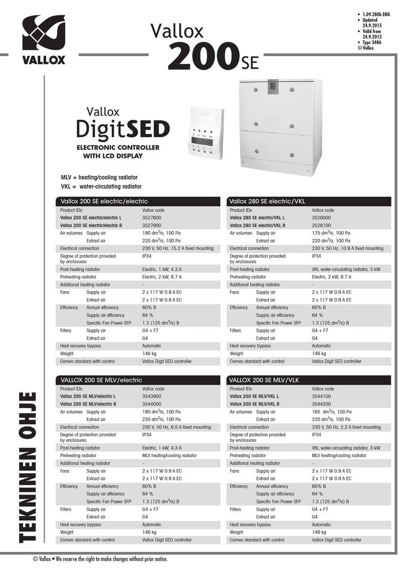
manuals.online logo
Brands
  1. Home
  2. •
  3. Brands
  4. •
  5. Vallox
  6. •
  7. Fan
  8. •
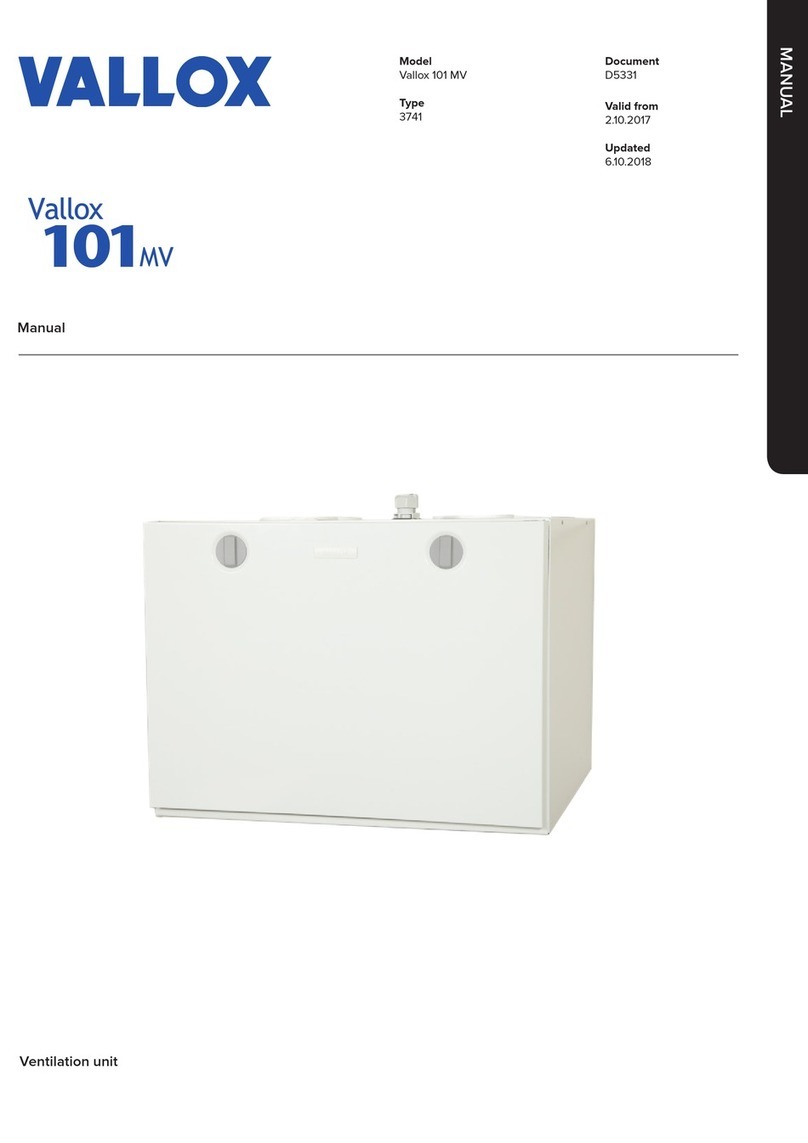
  9. Vallox A3741 User manual

Vallox A3741 User manual

This manual suits for next models

1

Other Vallox Fan manuals

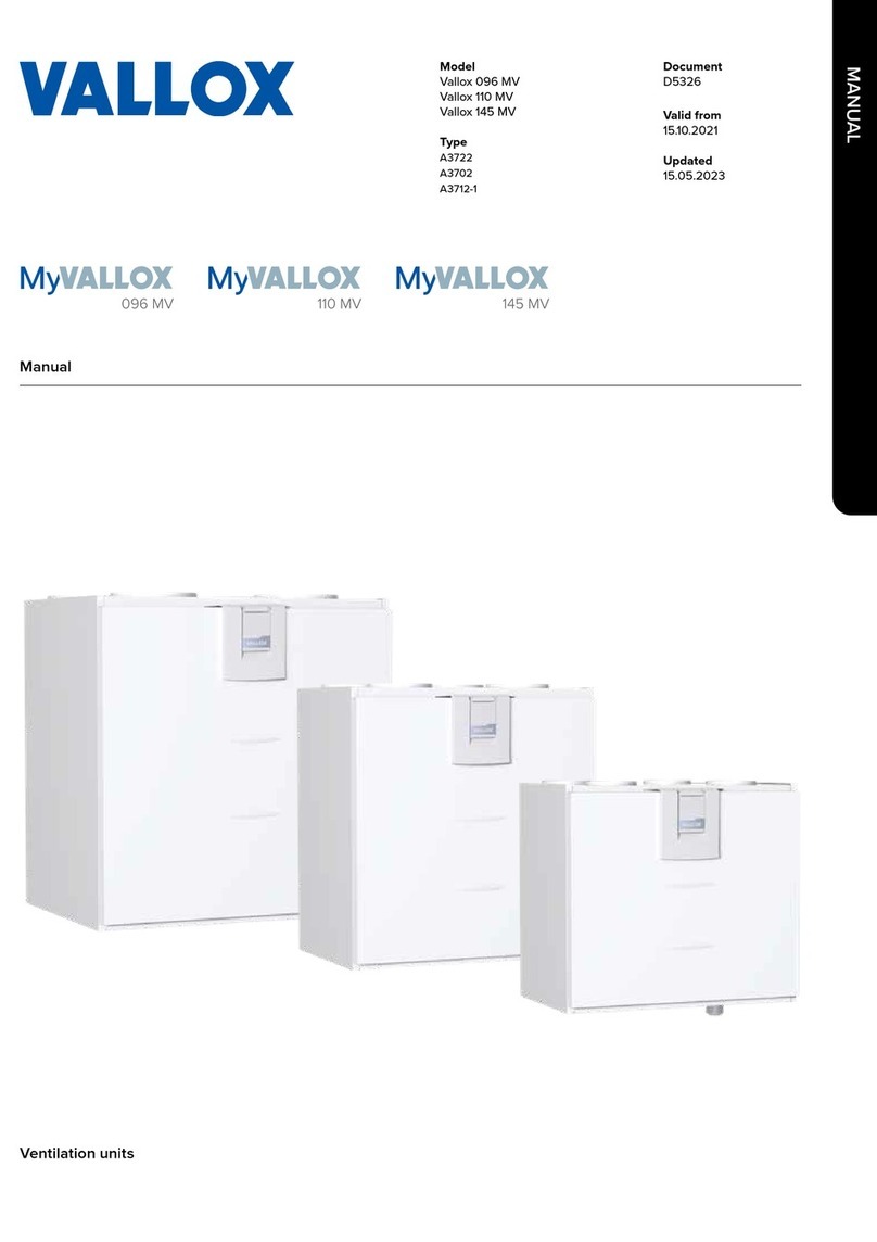
Vallox 096 MV User manual

Vallox

Vallox 096 MV User manual

Vallox 70 COMPACT R/L User manual

Vallox

Vallox 70 COMPACT R/L User manual

Vallox Vallox TSK Multi 50 MC R Operating instructions

Vallox

Vallox Vallox TSK Multi 50 MC R Operating instructions

Vallox 096 MC Series User manual

Vallox

Vallox 096 MC Series User manual

Vallox Vallox TSK Multi 50 MV EH User manual

Vallox

Vallox Vallox TSK Multi 50 MV EH User manual

Vallox 096 MC R Owner's manual

Vallox

Vallox 096 MC R Owner's manual

Vallox Vallox TSK Multi 50 MV EH User manual

Vallox

Vallox Vallox TSK Multi 50 MV EH User manual

Vallox 121 MC Series Owner's manual

Vallox

Vallox 121 MC Series Owner's manual

Vallox 51 MV User manual

Vallox

Vallox 51 MV User manual

Vallox DIGIT2 SE VKL Owner's manual

Vallox

Vallox DIGIT2 SE VKL Owner's manual

Vallox Capto TTC User manual

Vallox

Vallox Capto TTC User manual

Vallox 3756 User manual

Vallox

Vallox 3756 User manual

Vallox 75 Specification sheet

Vallox

Vallox 75 Specification sheet

Vallox 252 D Series Specification sheet

Vallox

Vallox 252 D Series Specification sheet

Vallox 3603 User manual

Vallox

Vallox 3603 User manual

Vallox Exxeo 150 User manual

Vallox

Vallox Exxeo 150 User manual

Vallox 132 E Series Specification sheet

Vallox

Vallox 132 E Series Specification sheet

Vallox 096 SE R Owner's manual

Vallox

Vallox 096 SE R Owner's manual

Vallox 252 M User manual

Vallox

Vallox 252 M User manual

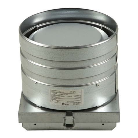
Vallox 15P-EC User manual

Vallox

Vallox 15P-EC User manual

Vallox 51 MV User manual

Vallox

Vallox 51 MV User manual

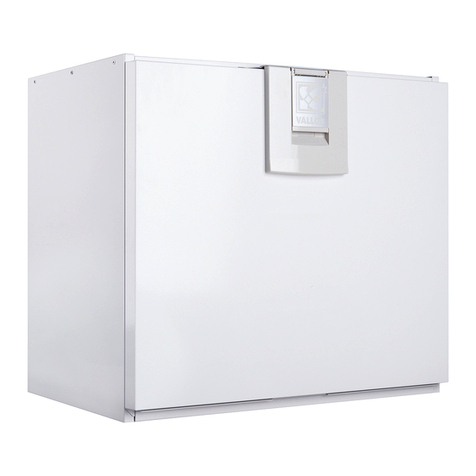
Vallox A3712-1 User manual

Vallox

Vallox A3712-1 User manual

Vallox 90 SE R Manual

Vallox

Vallox 90 SE R Manual

Vallox Vallox TSK Multi 50 MV EH User manual

Vallox

Vallox Vallox TSK Multi 50 MV EH User manual

Popular Fan manuals by other brands

Minka Group minkaAire Wave F843 instruction manual

Minka Group

Minka Group minkaAire Wave F843 instruction manual

Airflow Adroit DV50 instruction manual

Airflow

Airflow Adroit DV50 instruction manual

Vornado 270 Series owner's guide

Vornado

Vornado 270 Series owner's guide

comfort air TH-10D instruction manual

comfort air

comfort air TH-10D instruction manual

Livoo DOM386 instruction manual

Livoo

Livoo DOM386 instruction manual

Holmes BLIZZARD HAOF-90 owner's guide

Holmes

Holmes BLIZZARD HAOF-90 owner's guide

Taurus GRECO 16 ELEGANCE manual

Taurus

Taurus GRECO 16 ELEGANCE manual

Quorum PINNACLE installation instructions

Quorum

Quorum PINNACLE installation instructions

Monte Carlo Fan Company 3DIR58RBD-V1 Owner's guide and installation manual

Monte Carlo Fan Company

Monte Carlo Fan Company 3DIR58RBD-V1 Owner's guide and installation manual

Craftmade UH52 installation guide

Craftmade

Craftmade UH52 installation guide

Jocel JVA030658 instruction manual

Jocel

Jocel JVA030658 instruction manual

MIKA MFB1211/GR user manual

MIKA

MIKA MFB1211/GR user manual

Harbor Breeze RLG52NWZ5L manual

Harbor Breeze

Harbor Breeze RLG52NWZ5L manual

Allen + Roth L1405 instruction manual

Allen + Roth

Allen + Roth L1405 instruction manual

ViM KUBAIR F400 ECOWATT Technical manual

ViM

ViM KUBAIR F400 ECOWATT Technical manual

HIDRIA R10R-56LPS-ES50B-04C10 user guide

HIDRIA

HIDRIA R10R-56LPS-ES50B-04C10 user guide

BLAUBERG Ventilatoren CENTRO-M 100 L user manual

BLAUBERG Ventilatoren

BLAUBERG Ventilatoren CENTRO-M 100 L user manual

Triangle Engineering HEAT BUSTER SPL Series owner's manual

Triangle Engineering

Triangle Engineering HEAT BUSTER SPL Series owner's manual

manuals.online logo
manuals.online logoBrands
  • About & Mission
  • Contact us
  • Privacy Policy
  • Terms and Conditions

Copyright 2025 Manuals.Online. All Rights Reserved.

Manual
Model
Vallox 101 MV
Type
A3741
Document
D5331
Valid from
24.02.2020
Updated
05.02.2020
Ventilation unit
MANUAL
2
INTRODUCTION............................... . . . . . . . . 2
Safety ...................................................... . . . . . . .3
Installation ............................................. . . . . . . . . . .3
Guarantee .................................................. . . . . . . .3
Intended use ................................................ . . . . . . .3
Disposal of the ventilation unit ................................ . . . . . . .3
Safety signs used in the instructions .......................... . . . . . . .4
Installation options........................................... . . . . . . .4
System description .......................................... . . . . . . .4
Ventilation unit control ....................................... . . . . . . .5
Ventilation unit control options. .......................... . . . . . . . . . .5
Connecting the ventilation unit to the cloud service ........ . . . . . . . . . .5
Main parts .................................................. . . . . . . .6
INSTALLATION.................................. . . . . . . . . 7
Mounting on the wall ......................................... . . . . . . .7
Mounting on the ceiling ...................................... . . . . . . .7
Mounting the ceiling mounting plate...................... . . . . . . . . . .7
Installing the ventilation unit to the ceiling mounting plate . . . . . . . . . . . .8
Attic floor penetration plate.............................. . . . . . . . . . .8
Removal of condensing water ................................. . . . . . . .9
Dimensioning figures and space required for
installation of the Vallox Silent Klick siphon................ . . . . . . . . . .9
Space required by the alternative Vallox Silent Klick
siphon installation method (elbow) ....................... . . . . . . . . . .9
Measuring and adjusting the air flows of the ventilation unit ...... . . . . . . .9
Dimensions and duct outlets.................................. . . . . . .10
MAINTENANCE ................................ . . . . . . . 11
Before beginning maintenance work........................... . . . . . . 11
Changing the filters .......................................... . . . . . . 11
Cleaning the heat recovery cell ............................... . . . . . . 12
Condensing water ........................................... . . . . . . 12
Cleaning the fans ............................................ . . . . . . 13
TECHNICAL SPECIFICATIONS .... . . . . . . 14
Internal electrical connection ................................. . . . . . . 15
External electrical connection................................. . . . . . . 16
External electrical connection for controlling the MLV duct radiator . . . . . 17
Duct radiator operation....................................... . . . . . . 18
Duct radiator operation chart ................................. . . . . . . 19
In the outdoor air duct .................................. . . . . . . . . . 19
In the supply air duct.................................... . . . . . . . . . 19
Exploded view and parts list .................................. . . . . . 20
Conformity certificates ....................................... . . . . . . 21
NOTE
You can register your
Vallox MV ventilation
unit with the MyVallox
Cloud service and sign
in into your MyVallox
Cloud account at
www.myvallox.com.
CONTENTS
INTRODUCTION
3© Vallox Oy - All rights reserved
WARNING
The unit is not intended
for use by children
under 8 or by persons
with reduced sensory,
physical or mental
capabilities, or whose
lack of knowledge
and experience do not
ensure safe operation
of the unit.
Such persons can
use the unit under
supervision, or
by following the
instructions of someone
who is responsible for
their safety.
Children must be
supervised and not be
allowed to play with the
device.
SAFETY
Safe and appropriate handling requires knowledge of the basic safety
regulations, and of the intended use of the ventilation system. Read
this manual before operating the ventilation unit. Retain the manual for
later reference. If you lose the manual, it can be downloaded from our
website.
This user manual contains all the information necessary for safe
operation of the system. All persons who operate and maintain
the ventilation system must follow the instructions provided in this
manual. Furthermore, all local accident prevention regulations must be
observed.
Installation
Installation and setup should be carried out only by qualified experts.
Electrical installations and connections must be carried out only by an
electrician and in compliance with local regulations.
GUARANTEE
The guarantee and liability exclude damage resulting from:
• Inappropriate use of the ventilation system or the control unit
• Incorrect or inappropriate installation, setup or use
• Neglect of instructions concerning transportation, installation, use,
or maintenance
• Structural or electronic modifications or changes made to the
software
INTENDED USE
All Vallox ventilation units have been designed to provide appropriate
and continuous ventilation so as to present no threat to health and to
maintain structures in good condition.
IMPORTANT
In order to ensure that the indoor air presents no harm to
health and remains optimal also for the structures of the
building, ventilation must be kept on without disruptions. It is
recommended that ventilation be left turned on during long
holidays also. This keeps the indoor air fresh and prevents
humidity from condensing in the ventilation ducts and structures.
It also reduces the risk of moisture damage.
DISPOSAL OF THE VENTILATION UNIT
Do not dispose of electronic devices with household waste. Follow
local laws and regulations on safe and ecological disposal of the
product.
NOTE
For further information,
go to www.vallox.com
INTRODUCTION
4
SAFETY SIGNS USED IN THE INSTRUCTIONS
INSTALLATION OPTIONS
• Vallox 101 MV can be mounted either on the wall, or on the ceiling
by using a mounting plate (optional).
NOTE
The standard
equipment and
available accessories
vary from country to
country.
DANGER
Indicates a hazard that
will result in death or
serious injury if not
avoided.
WARNING
Indicates a hazard that
can result in death or
serious injury if not
avoided.
IMPORTANT
Indicates a hazard that
can result in damage to
property or loss of data
if not avoided.
CAUTION
Indicates a hazard that
can result in minor or
moderate injury if not
avoided.
NOTE
Indicates essential
information about the
product.
TIP
Provides additional
information about the
use of the product and
its benefits.
INTRODUCTION
SYSTEM DESCRIPTION
1. Internet
2. WLAN
3. Router
4. WLAN/LAN
5. Additional switch
6. Sensors MyVallox Cloud
MyVallox Home
Vallox MV
MyVallox Control
Modbus KNX
KNX bus
module
1
23
4
5
6
5© Vallox Oy - All rights reserved
INTRODUCTION
VENTILATION UNIT CONTROL
Ventilation unit control options.
Operation of the Vallox ventilation unit can be controlled by the
following means:
• Through the My Vallox Control panel installed in the building.
• Through the MyVallox Home local area network connection
and the MyVallox Home/Cloud user interface.
• Through the MyVallox Cloud service and the MyVallox Home/
Cloud user interface.
• Through a remote monitoring service or building automation
that uses voltage signals or Modbus messages.
In addition to the integrated humidity and carbon dioxide sensor,
ventilation can also be adjusted automatically by using the
optional carbon dioxide, humidity, or VOC (air quality) sensor.
When these are used, ventilation remains optimal even when
the dwelling is unoccupied. Each user can use the week clock to
adjust the ventilation to fit their individual lifestyle.
Connecting the ventilation unit to the cloud
service
The ventilation unit can be connected to the MyVallox Cloud
service. The cloud service allows for controlling ventilation
remotely also, using e.g. a smartphone or tablet. Also the unit
software is updated automatically through the cloud service.
To connect to the cloud service, the ventilation unit must be
connected to the Internet via LAN and registered with the cloud
service. At the same time you create a MyVallox Cloud account
for yourself. Read more about the service at www.myvallox.com.
IMPORTANT
Apartment-specific
ventilation units allows
residents to adjust the
ventilation eciency.
Ventilation is controlled
based on the need e.g.
through the cooker
hood, ventilation
control panel, or a
separate control centre.
In order to ensure that
the indoor air presents
no harm to health and
remains optimal also
for the structures of the
building, ventilation
must be kept on
without disruptions.
It is recommended
that ventilation be
left turned on during
long holidays also.
This keeps the
indoor air fresh and
prevents humidity
from condensing in
the ventilation ducts
and structures. It also
reduces the risk of
moisture damage.
NOTE
For the MyVallox Cloud/
Home instructions,
please go to www.
techmanuals.info/
ValloxMV/ENG/
onlinehelp/webhelp
IMPORTANT
Prolonged overpressure
can result in damage
to the structures of the
building.
6
Extract air fan
1
Supply air fan
2
Fine filter for supply air
3
Heat recovery cell
4
Bypass damper of the HR cell
5
Coarse filter for supply air
6
Coarse filter for extract air
7
R model in the figure
MAIN PARTS
Post-heatingresistor (in the supply air duct)
8
Safety switch 9
Internal humidity sensor
10
Control panel
11
Carbon dioxide sensor (optional) 12
Humidity sensor (optional)
13
VOC sensor (Optional) 14
Ceiling bushing for electric wires 15
INTRODUCTION
1
5
3
6
8
9
10
7
2
4
13
1211 14
15
A
N
N
U
A
L
E
F
F
I
C
I
E
N
C
Y
R
A
T
I
N
G
O
F
E
X
T
R
A
C
T
A
I
R
H
E
A
T
R
E
C
O
V
E
R
Y
A
+
7© Vallox Oy - All rights reserved
MOUNTING ON THE WALL
NOTE
Avoid mounting the unit on a hollow, echoing partition wall or
on a bedroom wall, or prevent the conduction of sound.
The minimum distance between the top of the unit and the
finished ceiling surface is 30 mm. Note that during mounting the
unit rises 10 mm higher than the final height.
Mount the ventilation unit on the wall with a mounting plate, as shown
in the adjacent figure. Make sure that the unit is horizontally level after
mounting.
MOUNTING ON THE CEILING
Vallox 101 MV can be equipped with an optional ceiling mount plate.
To attach the ceiling mounting plate:
• On rafter frames or other frame structure with M8 thread bars so
that they withstand the weight of the unit.
• Ensure that the installation plate is horizontally level, as this
determines the position of the unit.
• The top edge of the white covering strip of the ceiling mounting
plate can be installed against the ceiling. Alternatively, a concealed
mounting method can be used, in which case the ceiling can be
30 mm below the top of the white covering strip.
Insulate the ducts against condensation also between the unit and the
ceiling mounting plate.
Mounting the ceiling mounting plate
1. Fasten the thread bars on the rafter frames or other frame
structure, and screw the nuts (E) onto the bars.
2. Lift the ceiling mounting plate in place.
3. Push a rubber damper (F) and a washer (G) to each thread bar.
4. Adjust the nuts so that the ceiling mounting plate is level.
5. Shorten the lower ends of the thread bars so that they are no more
than 5 mm below the nuts.
CAUTION
The ventilation unit is very heavy. Do not perform this
procedure alone.
INSTALLATION
INSTALLATION
1
2
NOTE
When installing the unit,
reserve a space of at
least 555 mm in front
of the unit for servicing
purposes.
8
INSTALLATION
Installing the ventilation unit to the ceiling
mounting plate
1. Install the ceiling mounting plate with M8 thread bars so
that it is horizontally level.
NOTE
The end of the thread bars must be 5 mm or less below
the fastening nut. Do not fasten the ceiling mounting
plate too tight to the ceiling. Ensure that the sliding bars
move and restore to their original position by pulling
from the operating levers (A).
The top edge of the white covering strip of the ceiling
mounting plate can be installed against the ceiling.
Alternatively, a concealed mounting method can be used,
in which case the ceiling can be 30 mm below the top of
the white covering strip.
2. Ensure that the insulation washers are in the outlet collars
below the ceiling mounting plate.
3. Remove the door before installing the ventilation unit to the
ceiling mounting plate.
4. Lift the ventilation unit close to the ceiling mounting plate
and feed the cables and the connection box through the
hole in the ceiling mounting plate on top of the ceiling.
NOTE
Remember to make a service door in the ceiling so that
the cables and the connection box can be accessed.
The distance between the service door and the ceiling
mounting plate must be around 500 mm.
Alternatively, the cables can be fed between the ceiling
mounting plate and the ventilation unit to the rear wall.
When the ventilation unit is lifted against the ceiling
mounting plate, the unit locks in place. Where needed,
guide the mounting hooks on the ceiling mounting plate
(B) to the grooves on the side panels of the ventilation unit.
There are operating levers (A) on the front bottom corners
of the ceiling mounting plate. When the levers have been
restored to the same level with the white covering strip
of the ceiling mounting plate, the unit has been locked in
place.
5. Where required, the unit can be detached from the ceiling
mounting plate. Remove the door of the unit. Lift the
unit slightly upwards and pull simultaneously from both
operating levers (A) of the ceiling mounting plate to detach
the unit from the ceiling mounting plate.
Attic floor penetration plate
The attic floor penetration plate (D) is optional. When an attic
floor penetration plate is used, the tightness of the vapour
barrier has to be ensured.
The attic floor penetration plate can be fastened on the
finished rear wall. The minimum distance of the attic floor
penetration plate from the finished side walls is 15 mm.
1
3
4
5
2
B
B
A
A
D
9© Vallox Oy - All rights reserved
INSTALLATION
38
140
141
75
R
L
291
291
147,5 147,5
53
REMOVAL OF CONDENSING WATER
Dimensioning figures and space required for
installation of the Vallox Silent Klick siphon
MEASURING AND ADJUSTING THE AIR
FLOWS OF THE VENTILATION UNIT
The accessories delivered with the unit include four (4) air flow
measuring tubes. These can be inserted in the ducts to allow for
easier ventilation adjustment.
NOTE
The Vallox Silent Klick
siphon package is
delivered with the unit.
Installation instructions
for the siphon are
enclosed with the
packaging, and can
also be found online at
www.vallox.com. When
the alternative siphon
installation method is
used, the ring seal and
the locking part must
be moved to the pipe
connection part that is
mounted on the wall.
Space required by the alternative Vallox Silent Klick
siphon installation method (elbow)
92
1
Ø6
16
10
DIMENSIONS AND DUCT OUTLETS
INSTALLATION
Air flow measurement points
1. A Supply air
2. B Extract air
Measurement points after the outlet collar. The fan curves indicate the
total pressure accounted for by duct losses.
Main parts
1. Extract air fan
2. Supply air fan
3. Fine filter for supply air
4. Heat recovery cell
5. Bypass damper of the HR
cell
R model in the figure.
In the L model, the parts are mirrored
6. Coarse filter for supply air
7. Coarse filter for extract air
8. Post-heating resistor
(in the supply air duct)
9. Safety switch
10. Internal humidity and
carbon dioxide sensor
Dimensions and duct outlets
Dimensions
Duct outlets
R model
Inner diameter of the female collar: 125mm
1. Supply air from the unit to the
apartment
2. Extract air from the apartment to the
unit
3. Exhaust air flowing outdoors from the
unit
4. Outdoor air to the unit
L model
Inner diameter of the female collar: 125mm
1. Exhaust air flowing outdoors from the
unit
2. Outdoor air to the unit
3. Supply air from the unit to the
apartment
4. Extract air from the apartment to the
unit
1
5
3
6
8
9
10
7
2
4
A
B
~ 596
125
136,5
461,5
154,5
443,5
238 122
598
104
322
484
24
13
598
53
500
447