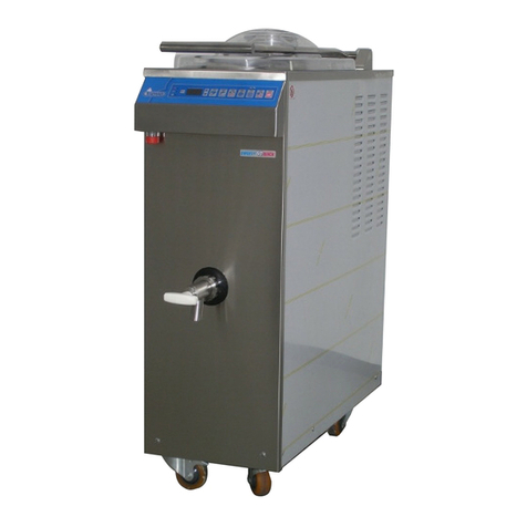
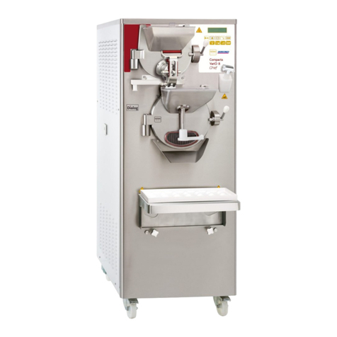
Valmar SWEETY 60 TTi Operating manual

VALMAR
HANDLING, OPERATING AND
MAINTENANCE GUIDE OF THE APPLIANCES
FOR THE PRODUCTION OF ICE CREAM
Model SWEETY TTi
Ver_SW_TT_001

2

3
TABLE OF CONTENTS
1
INSTRUCTIONS ON HOW TO USE THE GUIDE ...................................... 6
1.1
SYMBOLS USED IN THE GUIDE........................................................ 6
2
GENERAL FEATURES AND SPECIFICATIONS....................................... 7
2.1
GENERAL FEATURES........................................................................ 7
2.2
IDENTIFICATION OF THE APPLIANCE ............................................. 8
2.3
TECHNICAL SPECIFICATIONS.......................................................... 9
3
TRANSPORTATION AND PLACING OF THE APPLIANCE ................... 10
3.1
INSTRUCTIONS FOR PREVENTING INJURIES .............................. 10
3.2
UNLOADING THE APPLIANCE FROM THE LORRY........................ 10
3.3
UNPACKING OF THE APPLIANCE................................................... 11
3.4
PLACING THE APPLIANCE ON THE GROUND............................... 11
4
REQUIREMENTS AND CONDITIONS FOR NORMAL OPERATION OF
THE APPLIANCE ............................................................................................ 12
4.1
ENVIRONMENTAL CONDITIONS..................................................... 12
4.2
WATER SUPPLY REQUIREMENTS ................................................. 12
4.3
ELECTRICITY SUPPLY REQUIREMENTS....................................... 13
5
CONNECTING THE APPLIANCE ............................................................ 14
5.1
INSTRUCTIONS FOR PREVENTION OF INJURIES ........................ 14
5.2
CONNECTING THE APPLIANCE TO THE WATER SUPPLY........... 14
5.3
CONNECTING THE APPLIANCE TO THE POWER SUPPLY .......... 15
6
OPERATING THE APPLIANCE ............................................................... 16
7
CONTROL BOARD .................................................................................. 17
7.1
TOUCH SCREEN .............................................................................. 17
7.2
PUSH-BUTTON PANEL .................................................................... 31
7.3
FIRST USING OF THE MACHINE..................................................... 37
7.4
LANGUAGE SELECTION.................................................................. 38
7.5
DATA DOWNLOAD with a USB key .................................................. 39
7.6
UPLOAD OF NEW PROGRAM OR NEW SOFTWARE..................... 43
8
PROGRAMS ............................................................................................. 44
9
MENU PROGRAMS.................................................................................. 45
9.1
HOW ACCESS TO THE PROGRAM MENU: .................................... 45
9.2
STARTING OF THE PROGRAME..................................................... 46
9.3
SETTINGS OF THE PROGRAMME (shortcut button): ...................... 47
9.4
SETTINGS OF THE STEP:................................................................ 49
10
CHANGING PARAMETERS OF MACHINE ............................................. 50
10.1
RESET TO THE FACTORY SETTING .............................................. 50
10.2
LOCK/UNLOCK THE ACCESS OF OPERATION.............................. 52
11
PROTECTION OF THE USER AND OF THE MACHINE ......................... 55
11.1
PROTECTION OF THE USER........................................................... 55
11.2
ELECTRICAL OVERLOAD PROTECTION........................................ 55
11.3
THERMIC SAFETY DEVICES ........................................................... 55
11.4
PROTECTION OF THE COOLING SYSTEM .................................... 55
12
USE OF THE APPLIANCE ....................................................................... 55
12.1
INSTRUCTIONS FOR THE PREVENTION OF INJURIES ................ 55
12.2
BASIC RULES FOR OPERATING THE APPLIANCE........................ 56
12.3
PRODUCTION BASIN COVER LID................................................... 57
12.4
OUTLET PIPE.................................................................................... 57
12.5
OUTLET OF ICE-CREAM MIXTURE................................................. 58
12.6
BEFORE APPLIANCE USAGE.......................................................... 58
12.7
SMALL AMMOUNTS OF ICE-CREAM MIXTURE ............................. 59
12.8
AUTOMATIC MASS PRODUCTION CONTROLED BY PROGRAMS59
12.9
ICE CREAM MIXTURE - MASS MIXING ........................................... 59
13
CLEANING OF THE APPLIANCE............................................................ 59
13.1
INSTRUCTIONS FOR THE PREVENTION OF INJURIES ................ 59
4
13.2
CLEANING THE SURFACES OF THE APPLIANCE ......................... 60
13.3
WATER PIPES USAGE FOR CLEANING PURPOSES .................... 61
13.4
CLEANING OF PARTS THAT COME IN CONTACT WITH THE
MIXTURE OF THE ICE CREAM................................................................... 61
13.5
PRODUCTION BASIN DISINFECTION ............................................. 68
14
MAINTENANCE OF THE APPLIANCE .................................................... 68
14.1
INSTRUCTIONS FOR PREVENTION OF INJURIES ........................ 68
14.2
PROBLEMS, ERRORS AND TROUBLESHOOTING ........................ 68
14.3
REGULAR MAINTENANCE INSPECTION PLAN.............................. 69
14.4
TESTING START UP......................................................................... 69
14.5
REGULATION OF THE WATER FEED VALVE................................. 70
14.6
ENVIRONMENT TEMPERATURES BELOW 0°C ............................. 70
14.7
ORDERING SPARE PARTS.............................................................. 71

5
STARTING THE MACHINE
With quick key MIXING:
MIXING - button for the continuous mixing.
With quick key COOLING & FREEZING:
COOLING & FREEZING - button for the continuous mixing.
With quick key AUTOMATIC PASTEURIZATION:
AUTOMATIC PASTEURIZATION - button for the automatic
pasteurization at 85°C.
With quick key ONE:
ONE - button for the automatic low pasteurization at 65°C.
With quick key TWO:
TWO - button for the automatic pasteurization at 90°C suitable for
chocolate mixtures.
With quick key THREE
THREE - button for the automatic pasteurization at 85°C with
mixture micronization.
For more information read the entrie manual.

6
1 INSTRUCTIONS ON HOW TO USE THE GUIDE
Since we are in the company VALMAR aware that it is in yours as well as in our
interest that the machine would operate at its best and as cheap as possible we
have prepared this instruction manual, in order to assist you with your machine.
The instruction manual must be stored near the machine, so you will be able to
access it when needed.
Only authorized persons (operators), who know how to operate the appliance,
are allowed to handle and operate it. Operators must read and study the
manual carefully and they must follow the instructions.
The company VALMAR can not be held responsible for any kind of damage or
injuries occurred due to non-consideration of the instruction manual.
Further to these instructions, all applicable environmental legislation and
regulations regarding safety at work must be taken into consideration.
Handling the appliance required carefulness, which is expressed in the manual
with symbols.
1.1 SYMBOLS USED IN THE GUIDE
This symbol represents important content in the manual. You should study the
text accompanied with this symbol carefully. Disregard of instructions and
warning symbols may lead to serious personal injury and damage to the
appliance.
This symbol represents explicit prohibition of specific actions or operations.
When you see this symbol, special attention should be paid to what it refers.
This symbol calls your attention to the importance of the text as regards proper
handling of the appliance, but without danger of personal injury.
This symbol means that the content of the text is of a technical nature and is
related to technical specifications.
This symbol is an instruction to proceed with caution while engaging in a
specific operation referred to in the text.
This symbol means that the action to which it refers may also be carried out by
persons skilled in the operation of the appliance.
This symbol is a warning that any action or operation referred to in the text must
be carried out only by authorized servicing personnel.

7
2 GENERAL FEATURES AND SPECIFICATIONS
2.1 GENERAL FEATURES
The appliance is designed exclusively for the ice cream production and the
processing of fresh ice cream. The manufacturing company VALMAR cannot be
held liable in any way for personal injuries or damage caused to the appliance
in cases when the appliance has been used for any other purposes than those
specified.
The appliance consists of:
main construction
side panels and top cover
mixture producing cylinder with mixer
electrical assembly
hydraulic assembly (water)
cooling assembly
It is forbidden to reassemble, alter or in any way modify the appliance or any
part of the appliance without an express permission of the manufacturer.
This appliance is designed in compliance with the following European
directives:
CEE 2006/42/EC and updates,
CEE 2006/95/EC and updates,
CEE 2004/108/EC and updates,
CEE 89/109 and updates,
CEE 1935/2004 and updates,
CEE 2023/2006 and updates,
CEE 72/2002 and updates.
and following standards:
EN ISO 12100-2:2003+A1:2009
EN 60204:2006+A1:2009
EN ISO 14121-1:2007
EN ISO 13857:2008
EN 61310-1 + EN 61310-2
EN ISO 14159
This appliance is fully compliant with all legal standards for operational safety.
The level of operating noise does not exceed 75 dB (in front of the machine).
Cooling is carried out with the use of ecological gas (see the silver plate on teh
back side of the machine) and water condenser with the possibility of mounting
air condenser.
With the intention to provide our customers with a well-tested appliance, ready
for normal operation, the initial start-up is always carried out at the factory by
the manufacturer before the product is packed and shipped to our client.
Additional start-up and appliance's adjustments can be made on the client's
premises by technicians authorized by VALMAR.
Set the appliance in a suitable place, block it to ensure stability, and connect to
the water and power supplies. Blocked and connected appliance is ready for
operation.

8
The price of the appliance does not include installation costs and the cost of the
demonstration of its operation.
The warranty does not include replacements or repairs of malfunctions caused
by incorrect connection of the appliance.
The quality and the quantity of the ice cream depend on:
temperature of the cooling water;
temperature of air;
final temperature of the mixture;
quantity and quality of the ice cream mixture.
Put the ingredients into the production basin, close the lid and press one of the
quick key , , , or START key. The appliance will produce the
needed mixture based on selected program.
Appliance operations:
simultaneous mixing and heating of the mixture untill the pre-selected
temperature (max 115°C),
simultaneous mixing and cooling of the mixture to 4°C and maintaining
the produced mass at a temperature of 4~5°C;
possible mixing modes in production basin:
constant,
impulzive,
fast,
slow.
The warranty does not include replacements or repairs of malfunctions caused
by incorrect use of the appliance.
2.2 IDENTIFICATION OF THE APPLIANCE
Every appliance has its own identification label, which is fixed on the backside
of the appliance.
The ID label contains the essential technical specifications of the appliance:
1. manufacturer
2. manufacturers address
3. model
4. serial number
5. power supply voltage
6. nominal frequency
7. maximum current
8. cooling gas type
9. cooling gas weight
10.power
11.year of manufacturing

9
The ID label must not be removed or damaged!
2.3 TECHNICAL SPECIFICATIONS
The appliances essential technical specifications:
power supply voltage (see appliance label)
maximum current (see appliance label)
power (see appliance label)
nominal frequency (see appliance label)
water consumption
production capacity
capacity of a cylinder cycle
weight
dimensions
All technical specifications, such as the weight, dimensions and power of the
appliance are not mandatory for the manufacturer and may change.
*
The water consumption in cylinder depends on:
the incoming water temperature,
the ice cream mixture (type),
the ice cream mixture temperature,
the required final ice cream temperature.
MODEL
SWEETY WEIGHT DIMENSION (mm) POWER
WATER FLUX
cca
SINGLE QUANTITY
VOLUME/CYCLE
Kg Width
Depth Height KW * l/ciklus Min kg Max kg
60TTi 186 350 950 1030 8 191 20 60
130 TTi 220 520 950 1030 13 370 40 130
180 TTi 248 640 950 1030 13 530 60 175
1
75
43
2
10
11
1
8
6
9

10
3 TRANSPORTATION AND PLACING OF THE
APPLIANCE
3.1 INSTRUCTIONS FOR PREVENTING INJURIES
Pay due attention to legally required safety measures.
At work wear suitable clothing. Do not wear ties, jeweller’s chains or belts,
which could get caught in the machine.
Do not shift or dislocate the safety switches or protective parts.
Make sure that the lifting device is in good condition and that its load capacity
exceeds the weight of the appliance (refer to the technical specifications data
sheet).
Lift the appliance following the instructions for its use and maintenance. Pay
attention to the handling and handgrip locations. The use of a suitable lifting
device is recommended.
While lifting or moving the appliance do not stand under the machine.
Do not turn the appliance after holding the cables or the water hose has lifted it.
If you have to attend to any work higher up above the appliance, you should use
a suitable ladder and not the appliance for support.
3.2 UNLOADING THE APPLIANCE FROM THE LORRY
Required devices are a hand lift for pallets and a forklift truck with load capacity
of at least 1,200 kg.
Lift the crate containing the appliance using the hydraulic palette lift and move it
as close to the open side of the lorry as possible.
Remove the hand lift from underneath and handle the crate with the forklift
truck. Make sure that the weight is focused on the holding points.
Remove the crate from the lorry with the forklift truck in reverse gear as soon as
the crate is moved out of the lorry, and lower the crate to the minimal height of
around 30 cm.
Slowly and carefully place the box containing the appliance in its place. To
move the appliance around on the premises use wheels, which are supplied
with the appliance.

11
3.3 UNPACKING OF THE APPLIANCE
Upon the delivery of the appliance check if the crate was not damaged during
transportation.
First the appliance is fixed on the pallet with two paking strips and then is
placed the carton box which is fixed to the pallet with two paking strip too.
When the machine is unpacked, make sure that the packaging is disposed in a
suitable manner and in compliance with standards on environmental safety.
3.4 PLACING THE APPLIANCE ON THE GROUND
Place the machine on a level solid surface with an adequate strength of at least
600 kg per m² for the weight of the machine, and position the appliance at least
60 cm away from the wall or other objects. Leave enough space in front of the
appliance to ensure comfortable access and work with the appliance.
While placing the appliance in position, block the front wheels (by pressing the
brake), which will ensure that the appliance will not be able to move.

12
4 REQUIREMENTS AND CONDITIONS FOR
NORMAL OPERATION OF THE APPLIANCE
Before connecting the appliance to electricity supply, the operator must make
sure that environment requirements have been met: the temperature and
humidity of the air must be appropriate and the water supply and electricity
networks comply with all requirements for normal operation of the appliance.
When the characteristics of either the water supply or electricity network fail to
meet the requirements for normal operation, the machine must not be
connected to power supply.
4.1 ENVIRONMENTAL CONDITIONS
Prior to connecting the appliance, the temperature and the humidity of the
environment, in which the appliance will be operated, must be assessed and
checked.
If room temperature drops under 0 ºC (273K), water must be released from the
condenser.
4.2 WATER SUPPLY REQUIREMENTS
Prior to connecting the appliance to the power source, the temperature,
pressure and water flow from the water supply network must be checked.
Permitted water temperature and water pressure from the water supply network:
Water supply must be checked for all conditions that are required for alimentary
use.
Low water pressure causes the cooling system to function improperly. The
cooling gas does not condense, thus causing the compressor to overload. In
such cases, the safety pressure valve kicks in and switches off the compressor.
The results of mixture treating and ice cream production when the water
pressure is too low are not as good as when the water pressure is normal.
The maximum presence of chlorides in water is 120 ppm. Exchangers are not
suitable for the use of salt water.
min.
max.
WATER TEMPERATURE
5°C 30°C
WATER PRESSURE 100kPa (1bar) 800kPa (8bar)
WATER FLOW 400 l/h /
min.
max.
AIR TEMPERATURE 10°C 38°C
AIR HUMIDITY 0% 85%

13
4.3 ELECTRICITY SUPPLY REQUIREMENTS
Prior to connecting the appliance to the power source, the voltage and the
maximum power current allowed in the network must be checked and the
appliance must be protected externally with FUSES and the MAIN SWITCH.
Permitted voltage of three-phase appliances (400/50/3):
Permitted voltage of three-phase appliances (230/50/3, 230/60/3):
Permitted voltage of one-phase appliances (230/50/1):
The diameter of each phase conductor must be of an appropriate dimension
(corresponding to the power of the fuses). It is also necessary checked the
frequency.
The MAIN SWITCH must be installed in the immediate vicinity of the appliance,
where it must be easily visible, accessible to the operator and appropriately
marked.
Magnetothermic differential FUSES (slot ≥3 mm) of appropriate dimensions
must be installed between the electricity network and the MAIN SWITCH.
model
m
ax. current
fuse type
SWEETY 60 TTi (one-phase) 230/50/1 16A SLOW
SWEETY 60 TTi (three-phase) 400/50/3 16A SLOW
SWEETY 130 TTi (three-phase) 400/50/3 25A SLOW
SWEETY 130 TTi (three-phase) 400/50/3 32A SLOW
The position of the MAIN SWITCH with the FUSES in the power circuit scheme
of the appliance:
nominal voltage
min. voltage
max. voltage
400V 380V (400V–5%) 420V (400V+5%)
nominal voltage
min. voltage
max. voltage
230V 220V (230V–5%) 240V (230V+5%)
nominal voltage
min.
voltage
max. voltage
230V 220V (230V–5%) 240V (230V+5%)

14
5 CONNECTING THE APPLIANCE
5.1 INSTRUCTIONS FOR PREVENTION OF INJURIES
When the characteristics of either the water supply or electricity network fail to
meet the requirements for normal operation, the machine must not be
connected to the power supply.
It is forbidden to connect the appliance to the power source when the floor
around the appliance is wet.
It is forbidden to connect the appliance to the power source if any of the side
panels and the cover is missing.
5.2 CONNECTING THE APPLIANCE TO THE WATER SUPPLY
The water supply regulation valve is connected to the WATER SUPPLY PORT.
The water outlet pipe is connected to the WATER OUTLET PORT and to the
outlet pipe leading to the drain. All these terminals have a diameter of 3/4" and
are located on the backside of the machine.
To connect the appliance to the water supply (water supply port) and the outlet
to the drain (water outlet port), use pipes capable of withstanding 1MPa and
measuring at least ½” in diameter (make sure upon the delivery that the pipes
are supplied with the appliance).
SWEETY 60
TTi
SWEETY 130
TTi
SWEETY 180 TTi
WATER
SUPPLY
(drinkable water)
WATER INLET
(condenser)
WATER OUTLET (condenser)
(kondenzator)
WATER SUPPLY
(drinkable water)
WATER INLET
(condenser)
WATER OUTLET (condenser)
(kondenzator)
WATER SUPPLY
(drinkable water)
WATER OUTLET (
condenser)
(kondenzator)
WATER INLET
(condenser)

15
If the appliance is meant to be used in areas with two separate water supplies,
two separate water connectors are built in it, one for each: a DRINKING
WATER SUPPLY PORT and a COOLING WATER SUPPLY PORT
(condenser).
The valve belonging to the cooling water supply must not be connected to the
DRINKING WATER SUPPLY PORT.
The valve belonging to the drinking water supply may be connected to the
COOLING WATER SUPPLY PORT and/or to the DRINKING WATER SUPPLY
PORT.
The valve should be opened after the appliance has been connected to the
water supply system.
5.3 CONNECTING THE APPLIANCE TO THE POWER SUPPLY
Only appropriately trained technicians are allowed to connect the appliance to
the electrical current. They must follow installation instructions and observe the
occupational safety regulations applying in the country in which the appliance is
being installed. They must read the instructions carefully and above all
thoroughly familiarize themselves with the sections on REQUIREMENTS AND
CONDITIONS FOR NORMAL OPERATION OF THE APPLIANCE and the
machine’s electrical circuit scheme.
Before connecting the appliance, all attachments that might have become loose
during transportation must be checked. Attachments that may have become
loose or disconnected must be screwed back on and tightened.
Connecting instructions for three-vein cable (one-phase appliances – 230/50/1):
Connecting instructions for four-vein cable (three-phase appliances – 230/50/3
or 230/60/3):
Connecting instructions for five-vein cable (three-phase appliances – 400/50/3):
phase type colour
L1 230 V ~ black
L2 230 V ~ brown
L3 230 V ~ grey
PE ground yellow-green
phase type colour
L1 230 V ~ brown
N 230 V ~ blue
PE ground yellow-green
phase type color
L1 400 V ~ black
L2 400 V ~ brown
L3 400 V ~ grey
N neutral blue
PE ground yellow-green

16
A test start-up of the appliance is carried out by an appropriately trained
electrician who has also connected the machine so as to make sure that it is
properly connected (see the section on MAINTENANCE).
If the appliance is correctly connected to the mains the mixer in the production
cylinder should be turning in counter clockwise direction.
Production basin r mixer, installed in appliances with built-in inverter, will rotate
in the correct direction regardless of the connecting position of either of the
phases.
After connecting the appliance to the electricity network, appropriately trained
electrician must also control the power consumption. The current must not
exceed the maximum allowed on the identification plate or sticker (see the
section GENERAL FEATURES AND SPECIFICATIONS).
6 OPERATING THE APPLIANCE
The user operates the appliance standing in front of appliance. This position
allows user to handle the control panel and the safety switch.
The appliance must be always under users control during operation.
The control panel is used to display the status or the operation phase the
machine is in, to perform settings and to show messages and errors while
producing ice cream.
The safety switch is used to safely and securely switch of the electronics. The
electronics is switched off by pressing down the switch-off key in the normal
position and then depressing it. The switch will normally remain down and must
be pulled back up by hand to return to its normal position.
The water pipe is used for cleaning of the appliance.
SAFETY SWITCH
CONTROL BOARD

17
7 CONTROL BOARD
Control board is composed from touch screen and control panel.
7.1 TOUCH SCREEN
7.1.1 Inactive home screen:
DESCRIPTION:
1
TUTOR MESSAGES help users giving them instructions
and information about the processing.They also provide
information on any errors and give warnings on
operations.
2
POSITION OF THE MACHINE (standby).
3
Use this button to enter in the
SETTINGS MENU
4
QUICK PROGRMS KEYS.
3
1
4
11
2

18
7.1.2
Settings menu screen:
DESCRIPTION:
1
Use this function to enter the
PROGRAM MENU
2
Use this function to enter
MACHINE PARAMETERS
3
Use this function to enter
LANGUAGE SELECTION
4
Function to be used only by
Valmar technicians
5
Digit password to enter the
CODE screen
8
6
9
1
11
11
7
3
4
5
2
10
11

19
6
Use this function to enter the
electronic info sheet and check
electronic sheet data: number,
latest update, software version,
etc.
7
Use this function to enter, check
and change settings such as
date, time, units of
measurement
(Celsius/Fahrenheit,
liters/gallons) or water quantity
8
Press the BACK button to return
to the previous screen
9
Press the HOME button to
return to the main screen
10
For technician - net connection.
By correct code you can access
to connection between touch
screen and computer, TV…
11
Use this function to return to
factory settings. Access to the
CODE screen. Digit password to
cancel all changes. All saved
values will be cleared.
7.1.3
Info menu screen:
1
4
2
3
5
6
7
8
9
10
11
12

20
DESCRIPTION:
1
Type of the machine.
2
Number of the data base.
3
The date of the last update.
4
Serial number of the electronic.
5
IP number.
7
Number of the software.
6
MAC address (media access control address)
8
Version – number of the firmware (relay board).
9
Total hours of the working.
10
Total hours of the standbay.
11
Press BACK to return to the previous screen.
12
Press HOME to return to the main screen.
7.1.1 Settings screen:
3
2
1
16
9
4
6
13
11
14
15
5
7
10
8
12
This manual suits for next models
2
Table of contents
Other Valmar Ice Cream Maker manuals