Valmet Stonel Eclipse EC Series Operating and maintenance manual

Installation, maintenance and
operating instructions
Stonel™ Eclipse™ valve monitor
EC series
© Valmet, 7EC70EN - 6/2022 Stonel product publication 105509revA

Read these instructions rst!
These instructions provide information about safe handling and operation of the Stonel Eclipse EC. If you require additional assistance, please
contact the manufacturer or manufacturer’s representative. Addresses and phone numbers are printed on the back cover.
Save these instructions.
Subject to change without notice.
All trademarks are property of their respective owners.
Table of contents
1. General 3
1.1 Introduction 3
1.2 Title plate markings 3
1.3 CE markings 3
1.4 Recycling and disposal 3
1.5 Safety precautions 3
1.6 Assembly drawing 4
1.7 Specifications for all models 4
1.8 Dimensions 5
2. Assembly and mounting 6
2.1 Instructions 6
2.2 Eclipse EC assembly figure 6
3. Maintenance, repair
and installation 7
3.1 Maintenance and repair 7
3.2 Installation 7
3.3 Specific conditions of use 7
4. Function specific details 8
4.1 Sensor/switching modules 8
4.1 Sensor/switching
modules 12
4.1 Sensor/switching modules 14
4.1 Sensor/switching
modules 16
4.2 Valve communication terminals (VCT) 18
4.2 Valve communication terminals (VCT) 20
5. Wireless Link user
guide 22
5.1 Getting started 22
5.2 Home screen 22
5.3 Locked screen 22
5.4 Device detail screen 23
5.5 More information screen 24
5.6 Diagnostics screen 24
5.7 Federal Communication Commission (FCC)
and Industrial Canada (IC) statements 25
6. Model/Type code 26
7. Regulatory, specific conditions
of use, and product marking
continued 28
8. Appendix 29
8.1 Controlled installation drawings 29

SerialModel Date
Sensor Ratings: ———————————————————
Note: ——————————————————————————————
WARNING ————————————————————————————
(Approval Markings and Hazardous Location Markings)
—————————————————————————————————
SAMPLE
1.2 TITLE PLATE MARKINGS
The limit switch has an identication plate attached to the cover.
1. Product name and manufacturer identification
2. Electrical rating(s)
3. Note
4. Warning
5. Approval markings*
6. Protection class information*
7. Identification plate markings:
8. Model
9. Serial number
10. Date
1. GENERAL
1.1 INTRODUCTION
This manual incorporates the Installation, Maintenance and Operation (IMO) instructions for the Eclipse EC series valve controllers. The Eclipse EC
is designed to provide position feedback indication and pneumatic control of on/o automated valves.
Note
The selection and use of the Eclipse EC in a specic application requires close consideration of detailed aspects. Due to the nature of the product
this manual cannot cover all the likely situations that may occur when installing, using, or servicing the Eclipse EC. If you are uncertain about the
use of this device, or its suitability for your intended use, please contact the manufacturer for assistance.
1.3 CE MARKINGS
The limit switch meets the requirements of European Directives and
has been marked according to the directive.
1.4 RECYCLING AND DISPOSAL
Most limit switch parts can be recycled if sorted according to material.
In addition, separate recycling and disposal instructions are available
from us. A limit switch can also be returned to us for recycling and
disposal for a fee.
1.5 SAFETY PRECAUTIONS
Do not exceed the permitted values! Exceeding the permitted values
marked on the limit switch may cause damage to the switch and
to equipment attached to the switch and could lead to uncontrolled
pressure release in the worst case. Damage to the equipment and
personal injury may result.
To prevent ignition of hazardous atmospheres, replace cover before
energizing the electrical circuits. Keep cover tightly closed when in
operation.
8
4
7
65
910
2
1
3EC70EN - 6/2022 | Stonel product publication 105509revA

Specifications
Materials of construction
Housing & air manifold plate Polycarbonate
Visual indicator drum Nylon
Visual indicator cover Polycarbonate
Fasteners Stainless steel
O-rings & seals Nitrile compound
Operating life Unlimited
Temperature range -40° C to 80° C (-40° F to 176° F)
Enclosure protection Type 4, 4X, and 6 and IP66 / IP67
Warranty
Sensing & communication
module
Five years
Mechanical components Five years
Unit weights
Standard 0.36 kg / 0.80 lb
Unit dimensions
Unit height
Cover removal clearance
49.53 mm [1.95 in]
62.23 mm [2.45 in]
Position sensing
Accuracy Within 1°
Repeatability Within 1°
Setting buffer 4° from set point (Rotational distance from
original set point where switch will energize on
return stroke)
Dead band (Hysteresis) 6° from set point (Rotational distance from
original set point where switch will de-energize)
Past band 15° past set point (Amount valve can rotate
past set-point without leaving ON state. Do not
rotate past this point during normal operation)
Max rotational range 120° (90° optimum)
Terminal block specifications
Recommended torque 4.42 in.lbs (0.5 Nm)
Conductor strip length 0.22 -0.25 in (5.5-6.5 mm)
Maximum wire size 30-12 AWG (0.5-2.5 mm2)
Wire type Stranded or solid
Environmental conditions
Location Indoor and outdoor
Maximum altitude 5000 m
Maximum humidity 90%
Pollution degree 4
Ratings and approvals* See official website
* Only models listed on manufacturer’s official website are approved per specific
rating.
1.6 ASSEMBLY
DRAWING
1. Cover
2. Body screws
3. Internal ground lug
4. Title plate
5. Body
6. Visual indicator drum
retaining screw
7. Visual indicator/trigger drum
8. Visual indicator drum
coupler
9. Drive block
10. Mounting plate screws
11. Mounting plate
12. Actuator shaft
4
2
7
8
6
5
3
9
11
1.7 SPECIFICATIONS FOR ALL
MODELS
See page 8 for function specic details.
12
10
1
Stonel product publication 105509revA | EC70EN- 6/2022
4

1.8 DIMENSIONS
Note
Stonel Eclipse EC certied dimensional drawing can be found on
manufacturer’s ocial website under the Download tab.
5/14/2021
ffmlaugebr
500142_3
SHEET 1
A
TOLERANCES*(UNLESS OTHERWISE SPECIFIED):
X.XXX ±.005 ANGLES ±0° 30'
X.XX ±.010 FINISH f 125 RMS
X/X ±.015 *DIMENSIONS: INCHES (UNLESS OTHERWISE SPECIFIED)
1
SCALE REV.
DRAWING NO.
SIZE
TITLE
APPD.
CHK.
DR.
DATE
RESTRICTED
THIS DRAWING AND ALL INFORMATION CONTAINED
HEREIN IS THE PROPERTY OF AND IS SUBJECT TO
CHANGE BY STONEL. DRAWING IS NOT TO BE
REPRODUCED OR REVEALED TO ANY OTHER PARTY
UNLESS AUTHORIZED BY STONEL.
NELES USA INC., FERGUS FALLS, MN 56537 USA
REVISIONS
OF
REVISION ECO DATE BY
6.13
[155.6 mm]
3.03
[77.0 mm]
0.62
[15.6 mm]
0.68
[17.2 mm]
1.96
[49.7 mm] 1.75
[44.5 mm]
1/2" NPT or M20
5EC70EN - 6/2022 | Stonel product publication 105509revA

2. ASSEMBLY AND MOUNTING
2.1 INSTRUCTIONS
Steps
Refer to Eclipse EC assembly gure when performing mounting and
assembly procedures. Eclipse unit and mounting kit are supplied
separately. From Eclipse shipping container, ensure items A, B, and
D are present. From the mounting kit, ensure items C, E, F, G, and H
are present.
1. Locate the mounting plate (Item H) and place on the actuator.
Using an M3 allen wrench, fasten with the four mounting plate
screws (Item G). Torque screws to 46 to 56 in.lbs (5.1 to 6.3
Nm).
2. Place visual indicator drive block (Item F) into slot in the
actuator shaft. Place visual indicator drum coupler (Item E)
onto the visual indicator drive block (Item E is only used in
applications with a Namur 1 mounting pattern). Next, place
the visual indicator/trigger drum (Item D) onto the visual
indicator drum coupler. Align the holes in all three items with
the threaded hole in the actuator shaft and fasten down with
the visual indicator drum retaining screw (Item C). Leave screw
loose in order to facilitate indexing of the visual indicator.
3. With the actuator in the closed position, center the visual
indicator drum until the CLOSED quadrants are centered to the
left and right of the long axis of the actuator. With an M4 allen
wrench, tighten down with the visual indicator drum retaining
screw. Torque screw to 79 to 96 in.lbs (8.9 to 10.9 Nm).
4. Set the Eclipse body (Item A) in place. With an M4 allen
wrench, torque the Eclipse body screws (Item B) to Torque
screws to 46 to 56 in.lbs (5.1 to 6.3 Nm).
5. After all wiring and sensor setting procedures have been
completed, install Eclipse cover and hand tighten.
Special notes
• Mounting of the Eclipse requires a Stonel mounting kit specic
to the actuator the Eclipse is to being mounted to.
• It is recommended that thread lubricant or anti-seize be used on
the Eclipse body screws (Item B) prior to assembly.
• In high cycle or high vibration applications, blue Loctite® may
be used on the mounting plate screws (Item G) and the visual
indicator drum retaining screw (Item C).
2.2 ECLIPSE EC ASSEMBLY
FIGURE
A. Eclipse EC unit
B. Body screws (2)
C. Visual indicator drum retaining screw
D. Visual indicator/trigger drum
E. Visual indicator drum coupler
F. Drive block
G. Mounting plate screws (4)
H. Mounting plate
I . Actuator
D
G
F
E
B
A
H
C
I
Stonel product publication 105509revA | EC70EN- 6/2022
6

3. MAINTENANCE, REPAIR AND INSTALLATION
3.1 MAINTENANCE AND REPAIR
No routine maintenance of Eclipse units is required when installed in environments for which they are designed. Repair of Eclipse units must be
done by the manufacturer or by qualied personnel that are knowledgeable about the installation of electromechanical equipment in hazardous
areas. All parts needed for repair must be purchased through an authorized distributer for Stonel products to maintain warranty and to ensure the
safety and compliance of the equipment.
3.2 INSTALLATION
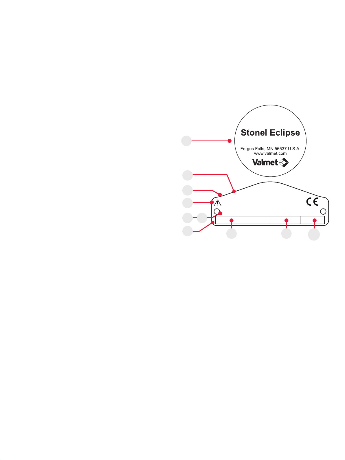
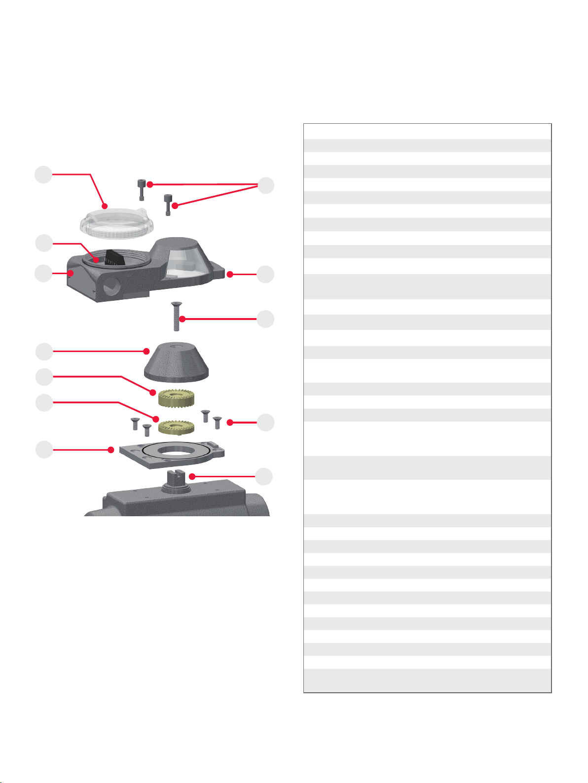
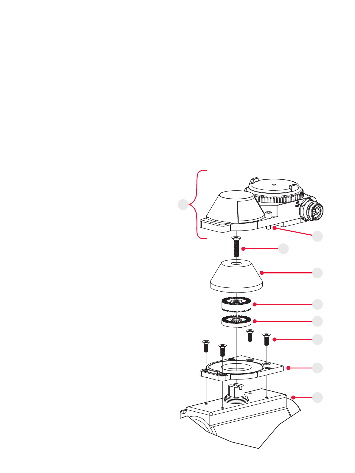
ATTENTION: IF REQUIRED, THE ECLIPSE HOUSING
CAN BE GROUNDED TO EARTH POTENTIAL BY
THE INTERNAL GROUND LUG. (SEE ASSEMBLY
DRAWING 1.6 ITEM 3 ON PAGE 4)
ATTENTION: IN ORDER TO MAINTAIN ENCLOSURE
TYPE AND IP RATINGS, COVER SHALL BE
TIGHTENED BY HAND UNTIL COVER MAKES
CONTACT WITH THE HOUSING. DO NOT USE ANY
TOOL TO TIGHTEN THE COVER.
WARNING
Solenoid power supplied must be limited with a
fuse or circuit breaker rated to 2 Amps maximum.
ATTENTION: IF THE UNIT IS USED IN A MANNER
NOT SPECIFIED BY STONEL, THE PROTECTION
PROVIDED BY IT MAY BE IMPAIRED.
CAUTION: TO MAINTAIN SAFETY, ONLY POWER
SUPPLIES THAT PROVIDE DOUBLE/REINFORCED
INSULATION, SUCH AS THOSE WITH PELV/SELV
OUTPUTS, SHALL BE USED. (AS APPLICABLE)
Field wiring
• This product comes shipped with conduit covers in an eort to
protect the internal components from debris during shipment and
handling. It is the responsibility of the receiving and/or installing
personnel to provide appropriate permanent sealing devices
to prevent the intrusion of debris or moisture when stored or
installed outdoors.
• Use eld wiring rated at least 10 K (+10° C) above ambient
temperature.
All models
WARNING
EXPLOSION HAZARD. DO NOT CONNECT OR DISCONNECT
WHEN ENERGIZED UNLESS THE AREA IS FREE OF
IGNITABLE CONCENTRATIONS.
Models with receptacles
WARNING
THE UNIT IS RATED FOR INGRESS PROTECTION WHEN
THE MATING CORDSET IS ATTACHED. THE MATING
CORDSET SHALL REMAIN CONNECTED DURING
OPERATION AND SHALL ONLY BE DISCONNECTED /
RECONNECTED BY TRAINED SERVICE PERSONNEL. IF
THE MATING CORD SET IS DISCONNECTED, IT IS THE
RESPONSIBILITY OF THE SERVICE PERSONNEL TO
INSTALL AN APPROPRIATELY RATED CAP (NOT SUPPLIED)
OVER THE RECEPTACLE TO MAINTAIN THE RATED
INGRESS PROTECTION OF THE UNIT.
When installed in Division 2 areas in the United States and Canada, a
Division 2 FM approved Turck eurofast® or minifast® cordset and the
use of a tool-secured Turck lokfast® guard is required.
Because the unit is rated for Ingress Protection with the mating cordset
attached, care must be taken when selecting the cordset to ensure it is
rated by the manufacturer with equivalent Ingress Protection ratings to
the unit.
The Turck lokfast® guard renders the cordset not “normally arcing”
and maintains ingress protection rating by making the connection tool
secured. Refer to the lokfast® guard’s documentation for details on
releasing the locking mechanism.
The cordsets, as specied above, are available with cable rated
for various wiring methods, such as ITC, PLTC, MC, etc. It is the
responsibility of the installer, or end user, to install this product
in accordance with the wiring method(s) specied by the cordset
manufacturer.
It is the responsibility of the installer, or end user, to install this product
in accordance with the National Electrical Code (NFPA 70) for the US,
CE Code, Part I for Canada, or any other national or regional code
dening proper practices.
7EC70EN - 6/2022 | Stonel product publication 105509revA

4. FUNCTION SPECIFIC DETAILS
4.1 SENSOR/SWITCHING MODULES
4.1.1 3 WIRE PNP / NPN SWITCHING SENSORS (30S, 30W)
Specifications
Configuration (2) 24 VDC N.O. solid state sensors.
Self-learning outputs for NPN/PNP/Sinking/
Sourcing PLC input cards.
(1) 24 VDC output for external solenoid.
Self-learning control input for NPN/PNP/Sinking/
Sourcing PLC output cards.
Voltage range 18 - 30 VDC
Minimum on current 2.0 mA
Maximum continuous current 0.1 amps
Maximum leakage current 0.0
Maximum voltage drop 0.1 volts @ 10 mA
0.5 volts @ 100 mA
Operating power (1 LED “ON”
Solenoid “OFF”)
0.6 watts
Operating power (1 LED “ON”
2W Solenoid “ON”)
3.0 watts
Circuit protection Protected against short circuits and direct
application of voltage with no load.
Output Specifications
Solenoid input voltage 18 - 30 VDC
Solenoid output voltage 24 VDC
Solenoid output current 85 mA
Solenoid output power 2.0 watts
Circuit protection External solenoid output is short circuit protected
Bluetooth features (30W)* Allows Set Open / Set Closed via Bluetooth
Stroke times (Only functions when attached to
external solenoid)
Valve Position graph
Lifetime Cycle Count (non-resettable)
Wiring diagrams
+–+
–
12345678
Closed V
S
E
T
O
P
E
N
S
E
T
C
L
O
S
E
D
Solenoid
Power
Module
Status
VOpenSol Ctrl
Sol Out
s
e
c
o
n
d
s
P
u
s
h
f
o
r
2
R G R G
Signal
V +
MALE (PINS)
MALE (PINS)
1
1
2
2
5
5
4
4
3
3
5-PIN MICRO CONNECTOR (M12)
5-PIN MINI CONNECTOR
OPEN
V -
CLOSED
SOL CTRL
Pin
1
2
3
4
5
Signal
NOT USED
FEMALE (PINS)
FEMALE (PINS)
2
3
1
5
2
3
1
4
5-PIN MICRO CONNECTOR (M12)
3-PIN MINI CONNECTOR
NOT USED
SOL OUT -
SOL OUT +
NOT USED
Pin
1
2
3
4
5
Signal
NOT USED
SOL OUT -
SOL OUT +
Pin
1
2
3
Common receptacle options pin-out
Note
Consult factory for additional quick connector options.
* Unlocking the Bluetooth features (30W only)
The device is unlocked until any of the signals (Open/Closed/Solenoid)
are wired to a PLC/DCS card, at which time it locks and it cannot be
unlocked until unwired and power cycled.
Stonel product publication 105509revA | EC70EN- 6/2022
8

Bench test procedure and sensor setting instructions
WARNING
DO NOT APPLY EXTERNAL POWER TO SOL OUT +/-
TERMINALS. THIS MAY CAUSE PERMANENT DAMAGE TO
THE UNIT.
CAUTION: PERFORMING THIS PROCEDURE
WILL CAUSE THE SENSOR INPUTS TO CHANGE
STATE. PERFORMING THIS PROCEDURE IS NOT
RECOMMENDED DURING A LIVE PROCESS.
To test sensors, use a 24 VDC power supply. No series load resistor is
required.
1. Apply power across the V+ and V- terminal block points. (No
power required on open/closed terminals.)
2. Attach indicator such that the closed quadrants will face out when
in the closed position. This figure shows a Red Closed visual
indicator in the closed position.
M
a
g
n
et
M
a
g
n
e
t
M
a
g
n
et
G
r
e
e
n
R
e
d
G
r
e
e
n
R
e
d
3. Save set-points:
a. Operate actuator to the closed position.
b. Press and hold SET CLOSED button until closed LED is lit or
ashes (2 seconds). Release button.
c. Operate actuator to the open position.
d. Press and hold SET OPEN button until the open LED is lit or
ashes (2 seconds). Release button.
NOTE: If red or green LEDs ash when trying to set the set-point,
the magnet is too far away from the sensing element. Adjust Visual
Indicator drum to bring the magnet slightly closer to the sensing unit
and try again.
4. Setpoints are retained even after power is removed.
5. To electrically test solenoid output, connect Solenoid Control
Signal terminal to V+ or V-. The Solenoid Output will activate.
Note
If using only one of the sensors for valve position feedback, either
sensor may be used independently.
4.1.1 3 WIRE PNP / NPN SWITCHING SENSORS (30S, 30W) CONTINUED
Specifications for Wireless Link
Communication Bluetooth® technology; single mode
(not compatible with Bluetooth® Classic)
Frequency band 2.402-2.480 Ghz
Transmit power 4dBm or ~2.5 milliwatts
Data rate 1 Mbit/second; effective information transmit rate
~10 Kbits/second
Range Up to 100 meters (330 feet) in free space. Range is
reduced by obstructions between handheld device
and Wireless Link VCT. Line of site is not necessary.
Registrations FCC, IC, CE
CE compliance Exceeds industrial compliance standards
VCT identification VCTs in range will be displayed in order of signal
strength
VCT link One device accessed at a time between client (hand-
held device) and server (VCT). Each server accessed
by one client at a time
Application Stonel Wireless Link available from the App store
Hand-helds Compatible with iPhone® and iPad® with iOS 9 or
later
Power/Fault LED status
Module status Fault description
LED off Device does not have power
Solid green Normal operation
Flashing red Output shorted
No magnet detected
The Open or Closed output signal is shorted.
Unit temperature exceeds 80° C
Low supply voltage
Internal sensor fault - sensor may need replacing
9EC70EN - 6/2022 | Stonel product publication 105509revA

4.1.1 3 WIRE PNP / NPN SWITCHING SENSORS (30S, 30W) CONTINUED
Input
Common
Input
Card
Input
Common
Input
Card
1
2
3
4
Output
Common
Output
Card
1
2
24V +
0V
GND
I/O
Card
Power
Supply
1
2
3
8
7
6
5
4
Terminal Block
V+ (24V+)
Closed Output Signal (DI)
Open Output Signal (DI)
V- (0V)
Solenoid Control Signal (DO)
External Solenoid +
External Solenoid -
EC30_
3
2
1
Solenoid
Valve
Typical basic installation
Wiring considerations
The pins V+ (24V+) and V- (0V) provide power for the unit’s sensor
circuitry and solenoid output. These pins should be wired to the same
24 VDC (18-30 VDC) source used for eld wiring connections of the
input / output card(s). There is no isolation between V+ / V- pins to the
signal pins. The power supply used must be able to provide enough
power/current for the unit’s circuitry plus current required for the signals
and external solenoid.
The open and closed signal pins should be wired to the input card’s
signal input terminal. No connection to the common terminal is
required.
The solenoid control signal pin should be wired to the output card’s
output (switched) terminal. No connection to the common terminal is
required.
Self-learning signals
Every time power is cycled to V+ / V-, the device will test the signal
wires to learn what type of input and/or output card(s) are wired to
each signal. If a signal is open-circuit, the device will continue to test it
until a card is detected. If the open or closed signal is short-circuited,
the device will retest the signal once the short circuit is removed.
Like most solid-state sensors, some current restrictive input cards
may detect a momentary ON state while the device is booting. Most
input cards (especially those designed for solid-state sensors) will not
experience an ON state during boot up.
Stonel product publication 105509revA | EC70EN- 6/2022
10

11EC70EN - 6/2022 | Stonel product publication 105509revA

4.1 SENSOR/SWITCHING MODULES
4.1.2 SST N.C. SENSOR (34S)
Specifications
Configuration (2) Universal voltage N.C. 2-wire solid state
sensors
(2) Wire terminations for one solenoid
Voltage range 20 - 250 VAC 50/60 Hz; 20 - 250 VDC
Minimum on current 2.0 mA
Maximum continuous current 0.1 amps
Maximum leakage current <0.5 mA
Maximum voltage drop 6.7 volts @ 10 mA
7.5 volts @ 100 mA
Circuit protection Protected against short circuits and direct
application of voltage with no load.
Solenoid pass-thru specifications
Solenoid voltage range 20 - 250 VAC 50/60 Hz; 20 - 250 VDC
Maximum solenoid current 0.75 amps
Wiring diagrams
1 NC2
12345678
OPEN
S
E
T
C
L
O
S
E
D
S
E
T
O
P
E
N
Solenoid
Power
CLOSEDSOL
s
e
c
o
n
d
s
P
u
s
h
f
o
r
2
CNC C
SOL PWR
1 2
R G
Red closed
1 NC2
12345678
CLOSED
S
E
T
O
P
E
N
S
E
T
C
L
O
S
E
D
Solenoid
Power
OPENSOL
s
e
c
o
n
d
s
P
u
s
h
f
o
r
2
CNC C
SOL PWR
1 2
R G
Green closed
Common receptacle options pin-out
MALE (PINS)
MALE (PINS)
1
1
2
2
5
5
4
4
3
3
5-PIN MICRO CONNECTOR (M12)
5-PIN MINI CONNECTOR Signal
OPEN / CLOSED C
[Jumper installed]
CLOSED NC
OPEN NC
SOL PWR 1
SOL PWR 2
Pin
1
2
3
4
5
Signal
OPEN NC
CLOSED NC
SOL PWR 2
SOL PWR 1
OPEN / CLOSED C
[Jumper installed]
Pin
1
2
3
4
5
Signal
NOT USED
FEMALE (PINS)
FEMALE (PINS)
2
3
1
5
2
3
1
4
5-PIN MICRO CONNECTOR (M12)
3-PIN MINI CONNECTOR
NOT USED
SOL 2
SOL 1
NOT USED
Pin
1
2
3
4
5
Signal
NOT USED
SOL 2
SOL 1
Pin
1
2
3
Note
Consult factory for additional quick connector options.
Stonel product publication 105509revA | EC70EN- 6/2022
12

4.1.2 SST N.C. SENSOR (34S) CONTINUED
Bench test procedure and sensor setting instructions
Note When performing this procedure on a Normally Closed (function
34) switch, the LEDs will turn o during the setup procedure instead of
on.
Use a 24 VDC power supply with series load resistor, (2K - 6K Ω),
connected to the 24 VDC+.
1. Connect 24 VDC + (with resistor) to the CLOSED C (common)
and OPEN C (common) terminals. Connect 24 VDC- to the
CLOSED NC and OPEN NC terminals.
2. Attach indicator such that the closed quadrants will face out when
in the closed position. This figure shows a Red Closed visual
indicator in the closed position.
M
a
g
n
et
M
a
g
n
e
t
M
a
g
n
et
G
r
e
e
n
R
e
d
G
r
e
e
n
R
e
d
3. Save set-points
a. Operate actuator to the closed position.
b. Press and hold SET CLOSED button until closed LED
changes state (2 seconds). Release button.
c. Operate actuator to the open position.
d. Press and hold SET OPEN button until the open LED
changes state (2 seconds). Release button.
NOTE: If red or green LEDs ash when trying to set the set-point,
the magnet is too far away from the sensing element. Adjust Visual
Indicator drum to bring the magnet slightly closer to the sensing unit
and try again.
4. Setpoints are retained even after power is removed.
5. To electrically test solenoid output, apply power to the SOL PWR
1 and SOL PWR 2 terminals.
Note
If using only one of the sensors for valve position feedback, either
sensor may be used independently.
Caution: Performing this procedure will cause the
sensor inputs to change state. Performing this procedure
is not recommended during a live process.
13EC70EN - 6/2022 | Stonel product publication 105509revA

4.1 SENSOR/SWITCHING MODULES
4.1.3 SST N.O. SENSOR (35S)
Wiring diagrams
1 NO2
12345678
CLOSED
S
E
T
O
P
E
N
S
E
T
C
L
O
S
E
D
Solenoid
Power
OPENSOL
s
e
c
o
n
d
s
P
u
s
h
f
o
r
2
CNO C
SOL PWR
1 2
R G
Red closed
1 NO2
12345678
OPEN
S
E
T
C
L
O
S
E
D
S
E
T
O
P
E
N
Solenoid
Power
CLOSEDSOL
s
e
c
o
n
d
s
P
u
s
h
f
o
r
2
CNO C
SOL PWR
1 2
GR
Green closed
Specications
Conguration (2) Universal voltage N.O. 2-wire solid state sensors
(2) Wire terminations for one solenoid
Voltage range 20 - 250 VAC 50/60 Hz; 20 - 250 VDC
Minimum on current 2.0 mA
Maximum continuous current 0.1 amps
Maximum leakage current <0.5 mA
Maximum voltage drop 6.7 volts @ 10 mA
7.5 volts @ 100 mA
Circuit protection Protected against short circuits and direct
application of voltage with no load.
Solenoid pass-thru specications
Solenoid voltage range 20 - 250 VAC 50/60 Hz; 20 - 250 VDC
Maximum solenoid current 0.75 amps
Common receptacle options pin-out
MALE (PINS)
MALE (PINS)
1
1
2
2
5
5
4
4
3
3
5-PIN MICRO CONNECTOR (M12)
5-PIN MINI CONNECTOR Signal
OPEN / CLOSED C
[Jumper installed]
CLOSED NO
OPEN NO
SOL PWR 1
SOL PWR 2
Pin
1
2
3
4
5
Signal
OPEN NO
CLOSED NO
SOL PWR 2
SOL PWR 1
OPEN / CLOSED C
[Jumper installed]
Pin
1
2
3
4
5
Signal
NOT USED
FEMALE (PINS)
FEMALE (PINS)
2
3
1
5
2
3
1
4
5-PIN MICRO CONNECTOR (M12)
3-PIN MINI CONNECTOR
NOT USED
SOL 2
SOL 1
NOT USED
Pin
1
2
3
4
5
Signal
NOT USED
SOL 2
SOL 1
Pin
1
2
3
Note
Consult factory for additional quick connector options
Stonel product publication 105509revA | EC70EN- 6/2022
14

4.1.3 SST N.O. SENSOR (35S) CONTINUED
Bench test procedure and sensor setting instructions
Note When performing this procedure on a Normally Open (function
35) switch, the LEDs will turn on during the setup procedure instead of
o.
Use a 24 VDC power supply with series load resistor, (2K - 6K Ω),
connected to the 24 VDC+.
1. Connect 24 VDC + (with resistor) to the CLOSED C (common)
and OPEN C (common) terminals. Connect 24 VDC- to the
CLOSED NO and OPEN NO terminals.
2. Attach indicator such that the closed quadrants will face out when
in the closed position. This figure shows a Red Closed visual
indicator in the closed position.
M
a
g
n
et
M
a
g
n
e
t
M
a
g
n
et
G
r
e
e
n
R
e
d
G
r
e
e
n
R
e
d
3. Save set-points
a. Operate actuator to the closed position.
b. Press and hold SET CLOSED button until closed LED
changes state (2 seconds). Release button.
c. Operate actuator to the open position.
d. Press and hold SET OPEN button until the open LED
changes state (2 seconds). Release button.
NOTE: If red or green LEDs ash when trying to set the set-point,
the magnet is too far away from the sensing element. Adjust Visual
Indicator drum to bring the magnet slightly closer to the sensing unit
and try again.
4. Setpoints are retained even after power is removed.
5. To electrically test solenoid output, apply power to the SOL PWR
1 and SOL PWR 2 terminals.
Note
If using only one of the sensors for valve position feedback, either
sensor may be used independently.
Caution: Performing this procedure will cause the
sensor inputs to change state. Performing this procedure
is not recommended during a live process.
15EC70EN - 6/2022 | Stonel product publication 105509revA

4.1 SENSOR/SWITCHING MODULES
4.1.4 NAMUR SENSOR (45S)
Specifications
Configuration (2) N.C. NAMUR sensors (EN 60947-5-6; IS)
(2) Wire terminations for one solenoid
Voltage range 5 - 25 VDC
Current ratings Target present
Target absent
current < 1.0 mA
current > 2.1 mA
Solenoid pass-thru specifications
Solenoid voltage range 30 VDC max
Maximum solenoid current 0.75 amps
Use with intrinsically safe repeater barrier. NAMUR sensors conform
to EN 60947-5-6 standard.
Reference controlled installation drawing #105521 for
proper intrinsic safe installation details. Find document in
the Appendix on page 29 or on the manufacturer’s
website.
STOP
Wiring diagrams
+ +
–
12345678
CLOSED
S
E
T
O
P
E
N
S
E
T
C
L
O
S
E
D
Solenoid
Power
OPENSOL
s
e
c
o
n
d
s
P
u
s
h
f
o
r
2
9 10
–
+–
SOL PWR
+–
G R
Red closed
+ +
–
12345678
OPEN
S
E
T
C
L
O
S
E
D
S
E
T
O
P
E
N
Solenoid
Power
CLOSEDSOL
s
e
c
o
n
d
s
P
u
s
h
f
o
r
2
9 10
–
+–
SOL PWR
+–
G R
Green closed
Common receptacle options pin-out
Signal
OPEN +
MALE (PINS)
MALE (PINS)
1
1
2
2
5
6
4
5
3
4
3
6-PIN MICRO CONNECTOR (M12)
6-PIN MINI CONNECTOR
OPEN -
SOL PWR +
CLOSED +
CLOSED -
Pin
1
2
3
4
5
SOL PWR -6
6
Signal
NOT USED
FEMALE (PINS)
FEMALE (PINS)
2
3
1
5
2
3
1
4
5-PIN MICRO CONNECTOR (M12)
3-PIN MINI CONNECTOR
NOT USED
SOL -
SOL +
NOT USED
Pin
1
2
3
4
5
Signal
NOT USED
SOL -
SOL +
Pin
1
2
3
Note
Consult factory for additional quick connector options.
Stonel product publication 105509revA | EC70EN- 6/2022
16

4.1.4 NAMUR SENSOR (45S) CONTINUED
Typical basic intrinsically safe circuits
NAMUR sensor circuit
Solenoid circuit
** Barrier o
ff state (target of
f): current in NAMUR sensor circuit >2.1 mA
Barrier on
state (target on): current in NAMUR sensor circuit <1.0 mA
power
source
Hazardous area
NAMUR
repeater
barrier
24 VDC
computer input
8 VDC
I = 0.5mA to 5.0mA**
NAMUR sensor
power
source
Hazardous area
solenoid
barrier
24 VDC
computer output
solenoid coil
Bench test procedure and sensor setting instructions
1. Connect 24 VDC + to the CLOSED (+) and OPEN (+) terminals.
2. Connect 24 VDC - to the CLOSED (-) and OPEN (-) terminals.
3. Attach indicator such that the closed quadrants will face out when
in the closed position. This figure shows a Red Closed visual
indicator in the closed position.
M
a
g
n
et
M
a
g
n
e
t
M
a
g
n
et
G
r
e
e
n
R
e
d
G
r
e
e
n
R
e
d
4. Save set-points:
a. Operate actuator to the closed position.
b. Press and hold SET CLOSED button until closed LED is
OFF (2 seconds). Release button.
c. Operate actuator to the open position.
d. Press and hold SET OPEN button until the open LED is OFF
(2 seconds). Release button.
NOTE: If red or green LEDs ash when trying to set the set-point,
the magnet is too far away from the sensing element. Adjust Visual
Indicator drum to bring the magnet slightly closer to the sensing unit
and try again.
5. Setpoints are retained even after power is removed.
6. To electrically test solenoid output, apply power to the
SOL PWR (+) and SOL PWR (-) terminals.
Note
If using only one of the sensors for valve position feedback, either
sensor may be used independently.
Caution: Performing this procedure will cause the
sensor inputs to change state. Performing this procedure
is not recommended during a live process.
17EC70EN - 6/2022 | Stonel product publication 105509revA

4.2 VALVE COMMUNICATION TERMINALS (VCT)
4.2.1 VCT WITH AS-INTERFACE COMMUNICATION (96S)
Specifications
Communication protocol AS-Interface v3.0
Configuration (2) Discrete inputs (sensors)
(1) Discrete output (solenoid)
Input voltage 26.5-31.6 VDC (AS-I voltage)
Output voltage 24 VDC (+/- 10%)
Quiescent current 32 mA
Maximum output current 85 mA
Maximum output power 2 watts
Output overcurrent
protection
100 mA
Default address 00
Maximum devices per
network
31
ID/IO codes ID = F; IO = 4; ID1 = F; ID2 = E (S-4.F.E.)
Bit assignment
Inputs
Bit 0 = not used
Bit 1 = not used
Bit 2 = Valve open
Bit 3 = Valve closed
Outputs
Bit 0 = not used
Bit 1 = not used
Bit 2 = output (OUT +/-)
Bit 3 = not used
Parameters
Bit 0 = wink
Bit 1-3 = not used
Wiring diagrams
+–
123456
S
E
T
O
P
E
N
S
E
T
C
L
O
S
E
D
Solenoid
PowerAS-i/FAULT
ASi
s
e
c
o
n
d
s
P
u
s
h
f
o
r
2
ASi OUT
+–+–
R G R G
Common receptacle options pin-out
Signal
ASi +
MALE (PINS)
1 2
43
MALE (PINS)
2 4
13
4-PIN MICRO CONNECTOR (M12)
4-PIN MINI CONNECTOR
not used
ASi -
not used
Pin
1
2
3
4
Signal
NOT USED
FEMALE (PINS)
FEMALE (PINS)
2
3
1
5
2
3
1
4
5-PIN MICRO CONNECTOR (M12)
3-PIN MINI CONNECTOR
NOT USED
OUT -
OUT +
NOT USED
Pin
1
2
3
4
5
Signal
NOT USED
OUT -
OUT +
Pin
1
2
3
Note
Consult factory for additional quick connector options.
Stonel product publication 105509revA | EC70EN- 6/2022
18

4.2.1 VCT WITH AS-INTERFACE COMMUNICATION AND EXTENDED ADDRESSING (96S) CONTINUED
Power/Fault LED status
AS-i status LED Fault description
LED off Device does not have power
Solid green Normal operation
Flashing red/green Output shorted
Flashing red/green No magnet detected
Flashing red/green Internal sensor fault - sensor may need replacing
Flashing yellow/red No data exchange (device address = 0)
Solid red No data exchange
Bench test procedure and sensor setting instructions
1. To test sensors, it is best to connect to an AS-i bus using an
AS-i power supply so that communication can also be tested.
However, if a network is not available, to set the open and closed
set points, use a 24 VDC power supply. Connect 24 VDC+ to
AS-i+ and 24 VDC- to AS-i -.
2. Attach indicator such that the closed quadrants will face out when
in the closed position. This figure shows a Red Closed visual
indicator in the closed position.
M
a
g
n
et
M
a
g
n
e
t
M
a
g
n
et
G
r
e
e
n
R
e
d
G
r
e
e
n
R
e
d
3. Save set-points:
a. Operate actuator to the closed position.
b. Press and hold SET CLOSED button until closed LED is lit (2
seconds). Release button.
c. Operate actuator to the open position.
d. Press and hold SET OPEN button until the open LED is lit (2
seconds). Release button.
NOTE: If red or green LEDs ash when trying to set the set-point,
the magnet is too far away from the sensing element. Adjust Visual
Indicator drum to bring the magnet slightly closer to the sensing unit
and try again.
4. Setpoints are retained even after power is removed.
5. To electrically test the solenoid output, the unit should be
connected to an AS-i bus and commanded to turn on.
Note
If using only one of the sensors for valve position feedback, either
sensor may be used independently.
WARNING
DO NOT APPLY EXTERNAL POWER TO THE OUTPUT
TERMINALS. THIS WILL CAUSE PERMANENT DAMAGE TO
THE UNIT.
Caution: Performing this procedure will cause the
sensor inputs to change state. Performing this procedure
is not recommended during a live process.
Wink feature
The Wink feature provides the capability of setting the closed or open
LEDs to ash or wink at a 2 Hz rate. This feature aids in physically
locating the unit on the network. It does not change valve state
indication in the control system.
19EC70EN - 6/2022 | Stonel product publication 105509revA

4.2 VALVE COMMUNICATION TERMINALS (VCT)
4.2.2 VCT WITH AS-INTERFACE COMMUNICATION AND EXTENDED ADDRESSING (97S & 97W)
Specifications
Communication protocol AS-Interface v3.0
Configuration (2) Discrete inputs (sensors)
(1) Discrete output (solenoid)
Input voltage 26.5-31.6 VDC (AS-I voltage)
Output voltage 24 VDC (+/- 10%)
Quiescent current 32 mA
Maximum output current 85 mA
Maximum output power 2 watts
Output overcurrent
protection
100 mA
Default address 0A
Maximum devices per
network
62
ID/IO codes ID = A; IO = 7; ID1 = F; ID2 = E (S-7.A.E.)
Bit assignment
Inputs
Bit 0 = Valve closed
Bit 1 = Valve open
Bit 2 = not used
Bit 3 = not used
Outputs
Bit 0 = output (OUT +/-)
Bit 1 = not used
Bit 2 = wireless link unlocked
[97W only]
Bit 3 = not available
Parameters
Bit 0 = wink
Bit 1-3 = not used
Wiring diagrams
+–
123456
S
E
T
O
P
E
N
S
E
T
C
L
O
S
E
D
Solenoid
PowerAS-i/FAULT
ASi
s
e
c
o
n
d
s
P
u
s
h
f
o
r
2
ASi OUT
+–+–
R G R G
Common receptacle options pin-out
Signal
ASi +
MALE (PINS)
1 2
43
MALE (PINS)
2 4
13
4-PIN MICRO CONNECTOR (M12)
4-PIN MINI CONNECTOR
not used
ASi -
not used
Pin
1
2
3
4
Signal
NOT USED
FEMALE (PINS)
FEMALE (PINS)
2
3
1
5
2
3
1
4
5-PIN MICRO CONNECTOR (M12)
3-PIN MINI CONNECTOR
NOT USED
OUT -
OUT +
NOT USED
Pin
1
2
3
4
5
Signal
NOT USED
OUT -
OUT +
Pin
1
2
3
Note
Consult factory for additional quick connector options.
Stonel product publication 105509revA | EC70EN- 6/2022
20
Table of contents
Other Valmet Industrial Equipment manuals
Popular Industrial Equipment manuals by other brands

Festo
Festo MPS 8049013 Getting started

Frick
Frick Vyper 700 Installation operation & maintenance

Cembre
Cembre RHU230-630 Operation and maintenance manual

Greenlee
Greenlee Gator Intelli-PUNCH instruction manual

Weir
Weir HYDRAU-FLO HF1105Z0001 Installation, operation and maintenance manual

RoboVent
RoboVent FlexPro Hi-Vacuum Series owner's manual