Valmet OC2R Installation instructions

Valmet Optical Consistency
Measurement - Valmet OC2R
Installation & operating
K20798 V1.1 EN

The copyright to this publication is owned by Valmet Automation Inc. or its affiliates ("Valmet"). This publication may
not be reproduced without permission and is intended for use by Valmet's customers only. Valmet reserves the right
to make changes to information contained in this publication without prior notice, and the customer should in all cases
consult Valmet to determine whether any such changes have been made.
Hardware and software products supplied by Valmet, including those referred to in this publication, are exclusively
subject to the terms of written contracts between Valmet and its customer. Unless otherwise set forth in such contract,
nothing in this publication including, without limitation, any statements regarding capacity, suitability for use, or
performance of such products, shall be deemed to constitute a warranty or commitment for any purpose nor shall it
be considered as part of such contract or giving rise to any liability by Valmet.
In particular, copyright and any other intellectual property rights to software applications described in this publication
are vested in Valmet and/or its third-party licensors, as applicable. The license to such software is governed
exclusively by the terms of the written Software License Agreement between the customer/user and Valmet, and any
access, installation or use of such software shall be deemed to constitute acceptance of the terms of Valmet’s
Software License Agreement.
The name "Valmet", Valmet’s product names and the Valmet logo are proprietary trademarks of Valmet Corporation
and/or its subsidiaries. Any other trademarks, product names, company names and logos are the property of their
respective owners.
© 2019 Valmet Automation Inc.
All rights reserved.
Valmet Automation Inc.
P.O. Box 177, FIN-87101 Kajaani, Finland
Tel. +358 (0)20 483120
www.valmet.com/automation
2019

Contents
1 Recycling and disposing............................................................................................ 5
2 Warnings & safety information................................................................................... 6
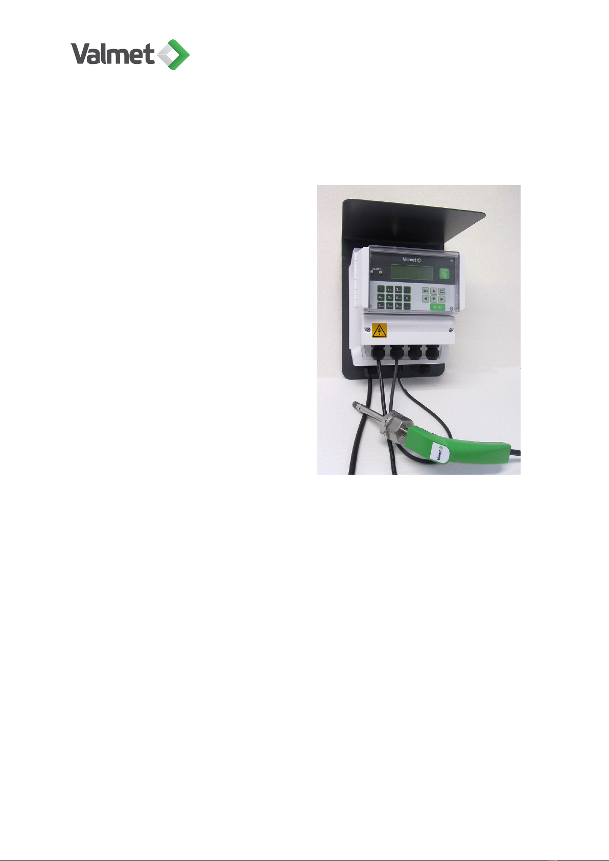
3 Valmet Optical Consistency Measurement – Valmet OC2R...................................... 7
3.1 Operating unit (TCU)....................................................................................... 7
3.2 Materials.......................................................................................................... 8
3.3 Acceptance inspection.....................................................................................8
3.4 Conformity to CE directives & CSA approval...................................................8
4 Safety recommendations......................................................................................... 10
5 Installing the sensor.................................................................................................12
5.1 Sensor dimensions........................................................................................ 12
5.2 Choosing the mounting location.................................................................... 13
5.3 Installation of process coupling & ball valve.................................................. 15
5.4 Adjusting sensor insertion depth....................................................................17
5.5 Installing sensor to process coupling.............................................................19
6 Installing the TCU.................................................................................................... 21
6.1 TCU............................................................................................................... 21
6.2 Electric connections of TCU.......................................................................... 22
6.3 Binary inputs..................................................................................................23
7 Setting up.................................................................................................................24
8 Operating................................................................................................................. 25
8.1 Operating with TCU....................................................................................... 26
8.2 Result displays...............................................................................................27
8.3 Operation map...............................................................................................28
9 Configuration............................................................................................................29
9.1 Recipe selection............................................................................................ 29
9.2 Output signal 1...............................................................................................29
9.3 Output signal 2...............................................................................................30

9.4 User settings..................................................................................................30
9.5 Device info.....................................................................................................31
9.6 Set clock........................................................................................................ 31
9.7 Digital inputs.................................................................................................. 32
9.8 Address..........................................................................................................32
10 Calibration................................................................................................................33
10.1 Principle of calibration....................................................................................33
10.2 Requirements for good calibration results..................................................... 33
10.3 Calibration methods.......................................................................................34
10.4 Creating a recipe........................................................................................... 35
10.5 Sampling for laboratory analysis....................................................................36
10.6 Entering lab. values....................................................................................... 37
10.7 Calibrating......................................................................................................38
10.8 Calibration history..........................................................................................39
11 Diagnostics.............................................................................................................. 41
11.1 Logs...............................................................................................................41
11.2 Diag. limits..................................................................................................... 42
11.3 Meas. values..................................................................................................42
11.4 Led.................................................................................................................42
11.5 Current output................................................................................................43
11.6 Error messages / warnings............................................................................ 44
12 Technical specification............................................................................................. 46
13 Spare parts.............................................................................................................. 48
14 Declaration of conformity......................................................................................... 49

1 Recycling and disposing
Almost all parts of the device are suitable for recycling when sorted by material. The
device may also be returned to the manufacturer, who will recycle and dispose of the
device for a fee.
This device contains the following parts, which must according to EU directive
2012/19/EU be recycled separately:
• printed circuit boards.
Further information about the safe handling and removal of above parts is available
from the manufacturer on request.
This device can contain some materials considered hazardous under EU Directives
2012/19/EU or 2006/1907/EC. For more information on these materials and their
recycling, see www.valmet.com/sustainability/sustainable-solutions/.
Recycling and disposing | 5 (48)
K20798 V1.1 EN - 1 - 12/2019

2 Warnings & safety information
DANGER:
Always ensure that the incoming voltage and frequency are correct
before making any electric connections. Wrong connection may
damage the equipment! The applicable safety regulations must be
closely followed in all installation work. All electric connections may
only be made by appropriately trained and authorized persons!
DANGER:
Before any welding works in the vicinity of the devices, make sure that
operating voltage is not connected.
Caution:
Before installing the process coupling and ball valve, make sure that
the process pipeline is empty and depressurized!
Caution:
During installation, maintenance and service operations, remember
that the sample line may contain hot sample or water – be careful!
Warnings & safety information | 6 (48)
K20798 V1.1 EN - 1 - 12/2019

3 Valmet Optical Consistency Measurement – Valmet
OC2R
Valmet Optical Consistency Measure-
ment – Valmet OC2R measures the total
and ash consistency of pulp based on the
amount of light reflected from the pulp.
The system uses a LED light source
which in practice does not wear in use.
Predefined linearization curves for differ-
ent pulp types enable easy calibration of
the measurement signal and facilitate the
setting up of the measurement.
The calibration curve is adjusted to the
process conditions by means of single-
point or two-point calibration. When
measuring ash-containing pulps, multi-
point calibration is applied to perform
compensation calculations that take into
account the variation of ash content in
the total consistency. Multi-point calibra-
tion is also used for ash consistency cali-
bration.
3.1 Operating unit (TCU)
TCU is the user interface, power supply and calculation unit of the system. The device
is operated by using the TCU keypad and four-line display. The TCU is mounted on a
protective cover which protects it from falling dirt, water, pulp, etc.
The TCU has the following connectors:
• sensor cable, sensor power supply and RS485 serial port;
• 4–20 mA current output (passive) to mill DCS;
• digital communication using HART® protocol;
• RS232 connection for a PC (for service purposes);
• mains voltage;
• binary inputs for recipe selection and sampling status.
Valmet Optical Consistency Measurement – Valmet OC2R | 7 (48)
K20798 V1.1 EN - 1 - 12/2019

3.2 Materials
All materials used in the exposed surfaces of the equipment have been selected and
manufactured for use in pulp and paper industry environments. The system cable is
PVC sheathed. The sensor is made of AISI316L stainless steel.
3.3 Acceptance inspection
After unpacking the delivery, make sure that it corresponds to the order. Check all
devices for possible transport damage.
Contents of delivery:
• Sensor probe assembly, with a 5 m or 10 m optical fiber cable.
• Optical TCU, with the selected communication.
• Sensor cable.
• Process mounting parts.
• Device manual and calibration quick guide.
• Selected options: 10 m extension for the sensor cable.
3.4 Conformity to CE directives & CSA approval
The entire system, consisting of a TCU with power supply, a sensor probe, and the
connecting cables (see chapter 4. TCU installation and cabling), has been designed to
meet the CE directives and their associated standards as stated in the Declaration of
Conformity document delivered with the device.
In order to meet the EMC directive, the following precautions must be taken:
1. All wiring must be shielded. Power supply electronics: shielded, coverage ≥ 80 %.
Interface cable: coverage 100 % aluminum.
2. All units must be tested as a complete system to conform with the relevant CE
directives and their standards.
When the units are used in other combinations, Valmet cannot guarantee their CE
directive conformity. In combination with customer-installed external devices, the units
may conform to EMC and safety requirements when properly installed and using an
adequate CE marked equipment.
Valmet Optical Consistency Measurement – Valmet OC2R | 8 (48)
K20798 V1.1 EN - 1 - 12/2019

Note:
System operator is responsible for the conformity with CE directives!
The conformity must be verified by inspection.
• Be careful when handling the equipment around vessels containing pressurized or
hot materials.
• Take the necessary safety precautions when mounting the equipment. Use
appropriate lifting gear, platforms and tools.
• The TCU is powered by hazardous voltages. The TCU box is CSA approved.
Valmet Optical Consistency Measurement – Valmet OC2R | 9 (48)
K20798 V1.1 EN - 1 - 12/2019

4 Safety recommendations
Note:
These safety recommendations are based on a risk analysis carried
out in accordance with the requirements of the Low Voltage Directive
in order to comply with European standards for CE marking. Read
carefully all safety recommendations and instructions before installing
any parts of the delivery.
General instruction
Follow precisely the instructions and recommendations when installing, connecting, or
servicing the equipment. These safety recommendations apply to a sensor installed with
an AC-powered TCU.
Note:
Always use only parts manufactured or approved by Valmet
Automation. Follow valid instructions and standards during installation.
Installing and connecting the sensor
Caution:
Before installing any mounting parts, make sure that the process
pipeline is empty and depressurized!
Welding or bolting and the subsequent inspection must take place in accordance with
the valid standards and regulations.
Read the installation instructions in this manual.
• Use approved lifting equipment during installation.
• Ensure that the sensor is fastened properly.
Safety recommendations | 10 (48)
K20798 V1.1 EN - 1 - 12/2019

• For dimensions and weight see Technical specifications.
• Before calibration make sure that the cable between sensor and TCU is properly
connected; this cable contains the optical fiber.
Installing the TCU
The TCU uses a hazardous voltage. Only a qualified electrician may connect the TCU.
Make sure to connect the earth correctly, double-check after connecting.
DANGER:
High voltage inside the TCU!
Safety recommendations | 11 (48)
K20798 V1.1 EN - 1 - 12/2019

5 Installing the sensor
5.1 Sensor dimensions
Before starting the installation, make sure that the sensor fits properly in the selected
installation site. Measured from the pipe surface, there must be at least 500 mm (~ 20")
of free space to allow the installation of the sensor. Make sure to leave sufficient room
around the sensor to perform this task.
Dimensions, OC2R Dimensions, process coupling
Installing the sensor | 12 (48)
K20798 V1.1 EN - 1 - 12/2019

5.2 Choosing the mounting location
Valmet OC2R must always be installed in a tur-
bulent flow. It is important to observe that tur-
bulence is influenced by consistency. Minimum
flow velocity is 1.0 m/sec (3.3 ft/sec).
Your Valmet experts will be pleased to assist in
selecting the location that will give the best
measurement result. The best results are ob-
tained when the sensor is installed to a pipe
section immediately after a pump, as the turbu-
lence is typically the strongest there.
Measured from the pipe surface, there must be
at least 500 mm (~ 20") of free space to allow
the installation of the sensor.
Note:
If there is a globe valve be-
tween the pump and sensor,
make sure that the valve is
fully open all the time to en-
sure a representative pulp
flow to the sensor.
Installing the sensor | 13 (48)
K20798 V1.1 EN - 1 - 12/2019

When Valmet OCR measures
unscreened pulps it must be installed
50–150 cm (approx. 2–5 ft) from a pump,
not immediately where the pump delivers
the pulp.
Also make sure to install the sensor
probe in the downstream direction and
adjust the insertion depth (see Sensor
depth adjustment) so that it is flush with
the pipe surface.
Installing the sensor | 14 (48)
K20798 V1.1 EN - 1 - 12/2019

5.3 Installation of process coupling & ball valve
1. Drill a hole to the pipe, diameter 25–35
mm (1–1.4"). Process coupling diameter
is 50 mm (2").
2. Clean the hole so that there is no burr
on the inside or outside. See photo on
the right: the burr must be removed so
that the edges of the hole are smooth,
otherwise fibers will get snagged to the
ragged edges and cause irregularities in
the measurement result.
3. Center the coupling to the drilled hole and make sure it is in the correct position,
and weld the coupling to the pipe.
• Screened pulps: the notch on the coupling (see arrow) is on the side facing the
pulp flow;
• Unscreened pulps: the notch on the coupling is on the "downstream" side (=
opposite to flow direction).
Screened pulp: Unscreened pulp:
Installing the sensor | 15 (48)
K20798 V1.1 EN - 1 - 12/2019

4. Insert O-ring on the welded coupling.
5. Screw down the ball valve to the weld-
ed coupling.
Installing the sensor | 16 (48)
K20798 V1.1 EN - 1 - 12/2019

6. Secure the ball valve to the coupling
with the locking screws and washers (3
pcs) to make sure that it will not be loos-
ened by vibration, knocks etc. Position
the screws and washers on the flat sec-
tions of the hexagonal section; for exam-
ple the hole indicated with an arrow in the
picture is not a good choice.
7. Close the ball valve. The locking
mechanism (indicated with an arrow)
prevents accidental opening and closing
of the valve.
5.4 Adjusting sensor insertion depth
As default the insertion depth is adjusted for screened pulps, so that the sensor tip is
inserted well into the pulp flow.
When measuring unscreened or unhomogeneous pulps, the sensor tip may catch
foreign objects contained in the flow. Such applications include OCC pulpers,
measurement points before coarse screens, broke pulpers under a paper machine, etc.
In these installations the sensor depth must be adjusted so that it protrudes only a little
into the pipeline:
Installing the sensor | 17 (48)
K20798 V1.1 EN - 1 - 12/2019

Open the 4 locking screws
(part 11) so that you can
move the locking ring (part
7) on the probe.
Move the locking ring 16 mm (0.6") towards the probe tip from its original position. In
newer sensor probes the position is marked on the probe. If there is no marking on the
sensor probe, draw a mark 8 mm (0.3") from the front surface of the locking ring (step
a). Push the locking ring towards the probe tip, until the rear edge of the ring is aligned
with the marking (step b). Then tighten the 4 locking screws.
Installing the sensor | 18 (48)
K20798 V1.1 EN - 1 - 12/2019

5.5 Installing sensor to process coupling
1. Separate sealing bushing (A) and sealing nut (B from each other. Make sure that
the O-ring (C) is properly installed in the sealing bushing (A). Push the sealing bush-
ing towards the probe tip until it stops at the lock ring.
2. Tighten the sealing bushing to the ball valve. Do not over-tighten!
3. Install the locking ring (D). This ring
ensures that the assembly is opened in
the correct order: the sealing nut must be
opened first before the sealing bushing
can be unscrewed. The locking ring must
be on the flat tool surface of the ball
valve, as shown in the photo.
Installing the sensor | 19 (48)
K20798 V1.1 EN - 1 - 12/2019

4. Open the ball valve and push the sen-
sor probe through the ball valve.
5. Screw down the sealing nut to the
sealing bushing and tighten it.
Note:
Before calibration, ensure that the optical fiber cable between probe
and TCU is properly connected and fastened, for example secured to a
cable rack with cable ties.
Installing the sensor | 20 (48)
K20798 V1.1 EN - 1 - 12/2019
Table of contents
Other Valmet Industrial Equipment manuals
Popular Industrial Equipment manuals by other brands

Pulsafeeder
Pulsafeeder Pulsalube 8 GS Ultra Operation & maintenance manual

DWK
DWK WHEATON Standard instruction manual

Shimano
Shimano SG-7R46 Service manual

Grundfos
Grundfos FireSAFE+ Residential instructions

Pine Research
Pine Research MSR Series user guide

Rexnord
Rexnord Falk Steelflex T10 Installation & maintenance