valmont INGAL EPS Pole Owner's manual

Technical Instruction
INGAL EPS Technical Instruction Floodlight Poles Page 1
Pole Assembly & Installation
For Floodlight Poles
The purpose of this technical instruction is to detail those actions necessary to ensure that Column/Mast sections are joined, assembled
and installed in compliance with the applicable design standards.
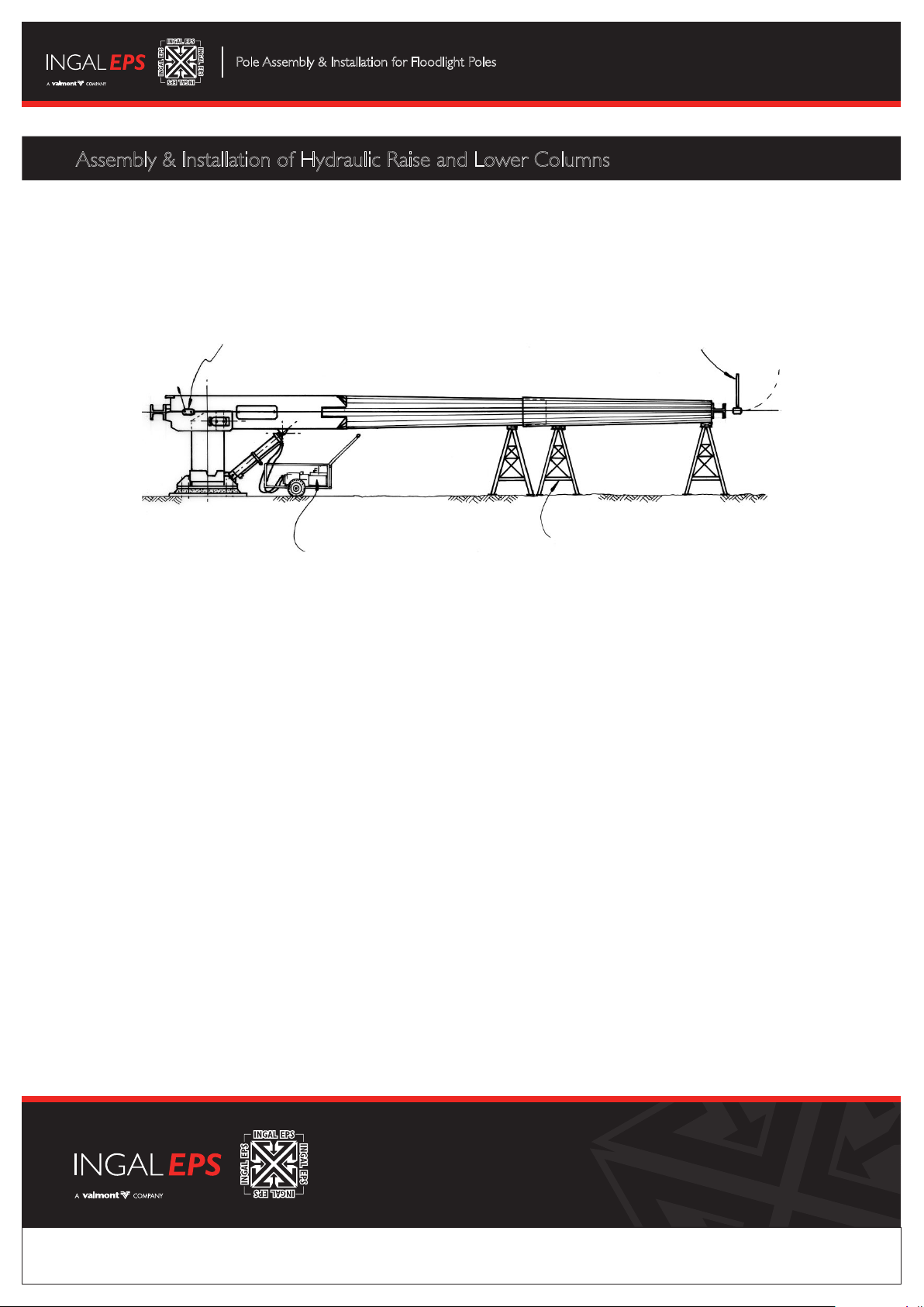
Scope: This procedure applies to the joining/assembly and installation of all column/mast sections, and to the assembly and installation of hydraulic raise
and lower columns.
1.0 Joining/Assembly of the Column/Mast Section
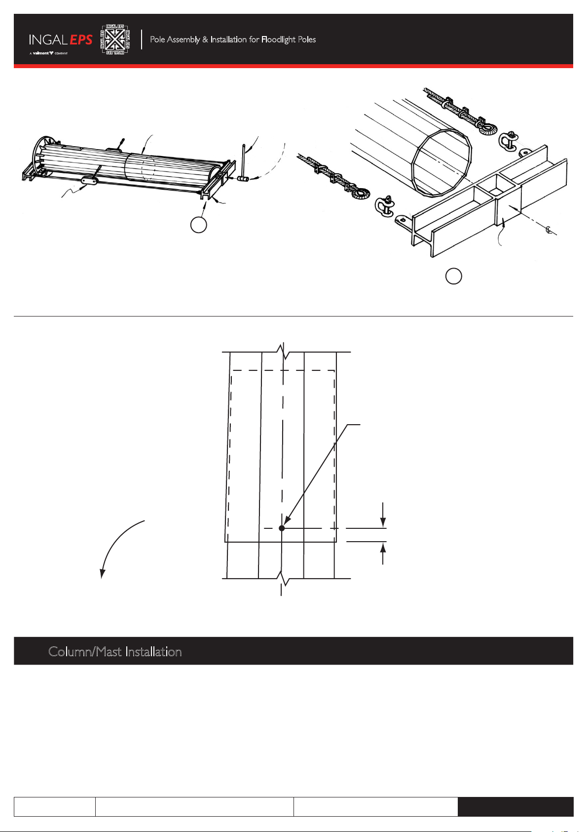
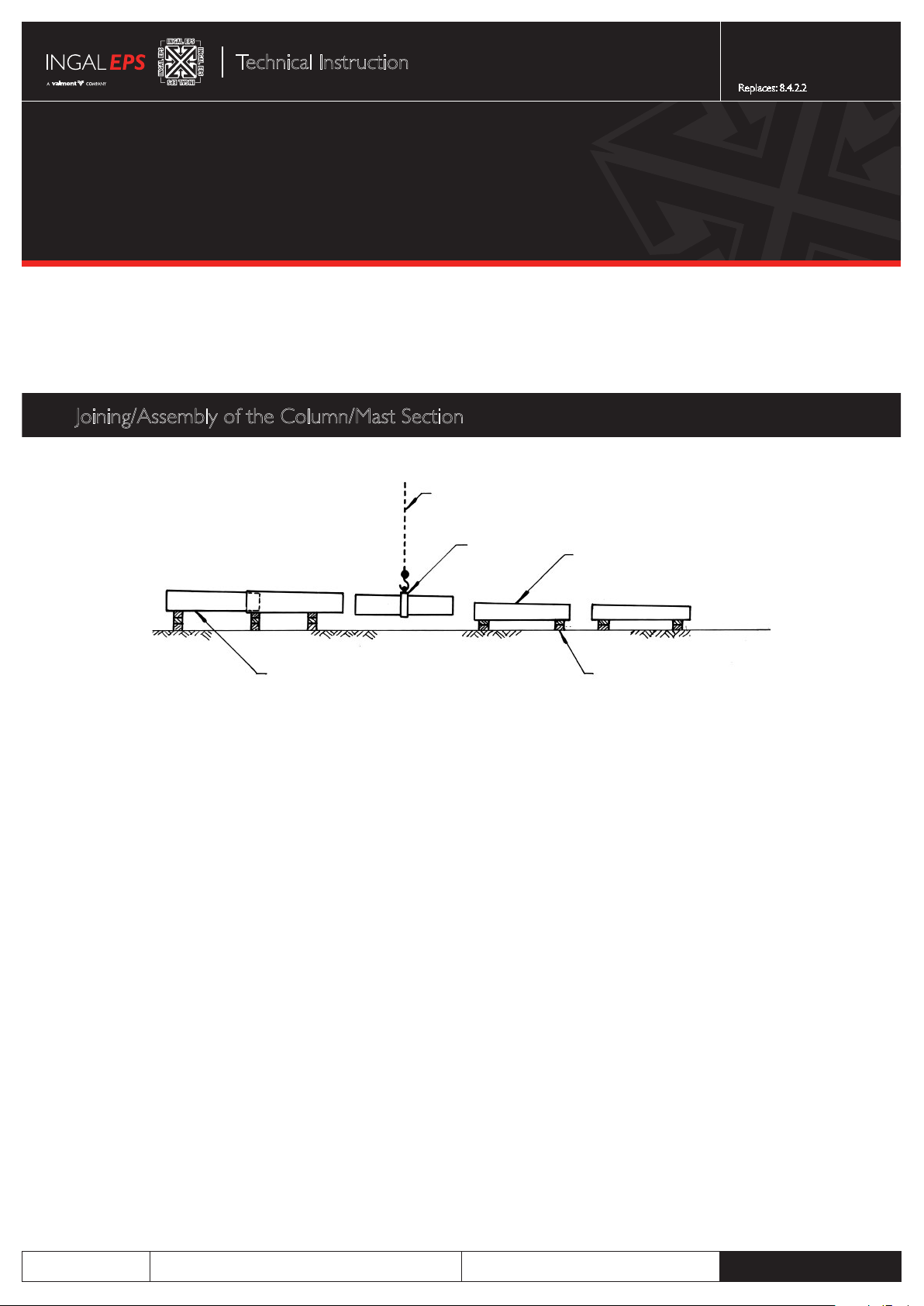
1.1 Arrange the base section onto packing with the access opening on the top and levelled so that the underside of the column section will be
horizontal.The height of the packing must be compatible with the base plate and the head frame dimensions so that both will be clear of the
ground when assembled. Seam welds of the column sections and climbing rung clips, if applicable, must be aligned along the length of the column,
(refer to figure 1).
1.2 Make sure that the column base plate is wedged to prevent rotation.
1.3 Check that the packing has a minimum of 300mm clearance of the slip joint length shown on the drawings to allow for any horizontal movement of
the column during assembly.
1.4 Sling the section for assembly at its centre of gravity and engage the sections, making sure that perfect alignment is maintained. Only one section at
a time is to be joined starting form the base section.
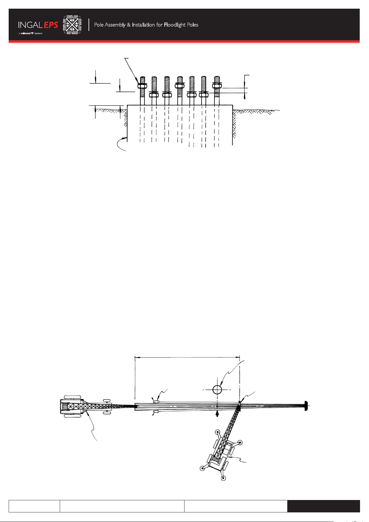
1.5 Assemble two 3 tonne lift – 5 tonne pull tirfors, one each side of the column, anchoring one end to the base plate or cross beam. At the end of the
column section being assembled a heavy steel section cross beam is arranged, blocked up in the horizontal plane on the column centre line while
the tirfor cables are attached as shown in figure 2. Noting only one section of the pole is assembled at a time starting from the base section.
1.6 Under strict supervision, operate the tirfors in unison to ensure that telescoping of the sections proceeds evenly about the column axis. During
this operation the cross beam can be hammered on the striking plate, (refer to figure 2), and the external surface of the slip joint can also be
hammered via a wooden block to assist in achieving a good joint.
1.7 Misalignment of the sections for any reason may lead to jamming, which will prevent good telescoping of the joint and may be difficult to rectify.
1.8 Check the theoretical slip joint length with respect to the actual slip joint length and continue to apply pressure as described in 1.6 above until no
further movement can be achieved.
1.9 Before removing the crane sling, pack up the newly assembled section to the required level ensuring that the packing is at least 300mm clear of
the next joint to be made. At the same time repack and wedge under the new slip joint before removing the original packing and proceed in this
matter until completion of assembly, keeping a careful check on alignment.
1.10 For Seesaw columns only, slip joints above hinge to be additionally secured with 2 tek screws – refer figure 3.
Figure 1.
Base Plate
Access Door
Crane Rope
Sling Column Sections
Packing
Horizontal or level
with ground line
G.L.
Doc. No: 8.6.02
Revision: 0
Date: 16-4-2013
Replaces: 8.4.2.2

INGAL EPS Technical Instruction Floodlight Poles Page 2
Pole Assembly & Installation for Floodlight Poles
2.0 Column/Mast Installation
2.1 The column foundation, supplied by others, must be designed and constructed in accordance with the applicable Standards to ensure that the
column is appropriate to the Column design parameters.
2.2 Before pouring the foundation it is recommended that a steel template be used to ensure that the bolts are correctly centred and vertical.The
protruding portion of the bolts should be coated with grease and protected by a cap.
2.3 Thread a nut and place a washer onto each of the anchor bolts so that they are under the column base plate and clear of the top of the concrete
by approximately 30mm.
2.4 Adjust two pair of nuts diametrically opposed at 90 degrees so that they are 10mm higher than the remainder and level with each other.
These four nuts will provide a means of obtaining vertical plumbing of the column – refer figure 4.
Figure 2.
5 Tonne Tirfor
(1 each side of column)
Slip Joint Sledge Hammer
Cross Beam both ends
Striking Plate
DETAIL 1
ELEVATION
1
Figure 3.
INSTALL 2 x 12G - 24 TPI x 20
LONG TEK SCREWS CLASS 3
HEX HEAD BARE (WITHOUT
WASHER) ONE THIS SIDE AND
ONE OPPOSITE SIDE
25
Raising and
lowering direction

INGAL EPS Technical Instruction Floodlight Poles Page 3
Pole Assembly & Installation for Floodlight Poles
2.5 Centre the lifting crane (A) as shown in figure 5. Attach a sling or chain formed into a noose arrangement at approximately two thirds of the
column height from the base. Attach a tirfor between the lifting lug on the base plate and the lifting sling.
The purpose of the above arrangement when lifting is to allow the noose sling to tighten around the column and the tirfor to stop the noose sling
from slipping up the column while also transferring the lifting force back to the pole base.
All lifting tackle must be checked for its capacity and adequacy for the mass of pole being lifted.
2.6 For larger columns it may be necessary to use a small mobile crane (B) to “tail in” the base end of the column as the main crane (A) is lifting.This
will prevent the base plate from dragging on the ground and maintain control of the base until the pole is held vertical by the lifting crane.
2.7 Before lifting the column, mark the base plate and foundation to ensure that the headframe and lighting array will be correctly orientated.
2.8 If necessary, rotate the column on the packing prior to lifting to facilitate the orientation.
2.9 Following the above, the column may now be lifted onto the foundation bolts.
2.10 With the column now erected on the foundation, place washers and nuts on all bolt threads.
2.11 Release the load from lifting crane (A). At this point the lifting sling noose should loosen and the tirfor rope can be used to guide the lifting sling
noose down the column as the lifting crane cable is run down.
2.12 Remove lifting tackle.
2.13 Plumb the column using the adjusting nuts.
2.14 With the column vertical, tighten all nuts to the underside of the base and tighten down the corresponding nuts above the base plate.
2.15 Fill the space between the base plate and the foundation with a non-shrink general purpose construction grout.
Figure 4.
2 pairs of nuts at 90º to each
other set above other nuts
for levelling purposes
Flat washers each side
of base plate
40mm
30mm
Concrete foundation
Figure 5.
Mobile Crane (B)
Base Plate
Tirfors
Approx. 2/3height
Foundation
Sling
Crane (A)
C.G.

For more information please contact INGAL EPS:
or visit www.ingaleps.com.au
Disclaimer The instructions included in this document have been written to provide guidance only for the assembly of the equipment therein described. Industrial Galvanizers
Corporation Pty Ltd is not liable for any direct, indirect or consequential loss or damage to property or personal injury that may arise in tort, equity or otherwise at
law as a result of following these instructions. | Copyright © 2013 Industrial Galvanizers Corporation Pty Ltd, trading as INGAL EPS.
Pole Assembly & Installation for Floodlight Poles
3.0 Assembly & Installation of Hydraulic Raise and Lower Columns
3.1 For Hydraulically raised and lowered columns the base may be mounted on the foundation bolts with a small crane and the column sections joined
together as per Section 1 of this procedure (figure 6).
The hydraulic unit can then be utilised to lift the column into its normal in service position and the use of a large lifting crane can be avoided.
Figure 6.
5 Tonne Tirfor
(1 each side of column) Sledge Hammer
Trestles
(may be moved to next section
to be assembled as required)
Hydraulic Unit
Table of contents
Popular Industrial Electrical manuals by other brands

TUMAC
TUMAC CHTR 40 Operation and maintenance

Murata
Murata GRM155R71E103KA01 Series Reference sheet

MICRO-EPSILON
MICRO-EPSILON optoNCDT 1220 operating instructions

SMA
SMA TS4-R-F Quick reference guide

Abtech
Abtech HVJB Series Installation, operation & maintenance instructions

Murata
Murata GRM32ER60G227ME05 Series Reference sheet