VALTIR Triton Barrier TL-2 User manual


Part No. 115661
© Valtir, LLC
www.Valtir.com 1 Revision C February 2023
Triton Barrier®
TL-2 & TL-3
Applications
Assembly Manual
15601 Dallas Parkway
Suite 525
Addison, Parkway, 75001
Important:These instructions are to be used only in conjunction with the
assembly, maintenance, and repair of the Triton Barrier®system. These
instructions are for standard assembly specified by the appropriate highway
authority. In the event the specified system assembly, maintenance, or repair
would require a deviation from standard assembly parameters, contact the
appropriate highway authority engineer. This system has been accepted for use
by the Federal Highway Administration for use on the national highway system
under strict criteria utilized by that agency. Valtir representatives are available for
consultation if required.
This Manual must be available to the worker overseeing and/or assembling the product
at all times. For additional copies, contact Valtir at (888) 323-6374 or download from
websites below.
The instructions contained in this Manual supersede all previous information and Manuals. All
information, illustrations, and specifications in this Manual are based on the latest Triton Barrier®
system information available to Valtir at the time of printing. We reserve the right to make
changes at any time. Please contact Valtir to confirm that you are referring to the most current
instructions.

www.Valtir.com 2 Revision C February 2023
Table of Contents
Customer Service Contacts ..........................................................................................................3
Important Introductory Notes ........................................................................................................3
Recommended Safety Rules for Assembly .................................................................................. 4
Safety Symbols .............................................................................................................................5
Warnings and Cautions.................................................................................................................5
Limitations and Warnings..............................................................................................................6
Important Introductory Notes ........................................................................................................7
Special Site Considerations ........................................................................................................11
Recommended Tools and Equipment.........................................................................................12
Deployment and Retrieval...........................................................................................................13
Checking the Assembly ..............................................................................................................16
End Treatment ............................................................................................................................17
Maintenance and Repair.............................................................................................................20
Visual Drive by Inspection..................................................................................................... 20
Walk-up Inspection................................................................................................................20
Deflection/Clear Zone .................................................................................................................24

www.Valtir.com 3 Revision C February 2023
Customer Service Contacts
Valtir is committed to the highest level of customer service. Feedback regarding the Triton
Barrier®system, its assembly procedures, supporting documentation, and performance is
always welcome. Additional information can be obtained from the contact information below:
Valtir:
Telephone:
(888) 323-6374 (USA Only)
(214) 589-8140 (USA or International)
E-mail: Valtir.com/Contact
Internet: Valtir.com
Important Introductory Notes
Proper assembly of the Triton Barrier®system is essential to achieve performance of the system
under appropriate federal and state criteria. These instructions should be read in their entirety
and understood before assembling the Triton Barrier®system. These instructions are to be used
only in conjunction with the assembly of the Triton Barrier®system and are for standard
assemblies only as specified by the applicable highway authority. In the event your system
assembly requires or involves deviation from standard parameters or, during the assembly
process a question arises, please contact the appropriate highway authority that specified this
system at this particular location for guidance. Valtir is available for consultation with that
agency. These instructions are intended for an individual who is qualified to both read and
accurately interpret them as written. They are intended for the individual who is experienced and
skilled in the assembly of highway products which are specified and selected by the highway
authority.
A set of product and project shop drawings are available from Valtir. The shop drawings will be
for each section of the assembly. These drawings should be reviewed and studied thoroughly
by a qualified individual who is skilled in interpreting them before the start of any assembly.

www.Valtir.com 4 Revision C February 2023
Important: Read safety instructions thoroughly and follow the assembly
directions and suggested safe practices before assembling, maintaining, or
repairing the Triton Barrier®system. Failure to follow this warning can result in
serious injury or death to workers and/or bystanders. It further compromises the
acceptance of this system by the FHWA. Please keep these instructions for later
use.
Warning: Ensure that all of the Triton Barrier®system Warnings, Cautions, and
Important Statements within the Triton Barrier®Manual are completely followed.
Failure to follow this warning could result in serious injury or death in the event of
a collision.
Recommended Safety Rules for Assembly
* Important Safety Instructions *
This Manual must be kept in a location where it is readily available to persons who are skilled
and experienced in the assembly, maintenance, or repair of the Triton Barrier®system.
Additional copies of this Manual are immediately available from Valtir by calling (888) 323-6374.
This Manual may also be downloaded directly from the websites indicated below. Please
contact Valtir if you have any questions concerning the information in this Manual or about the
Triton Barrier®system.
Always use appropriate safety precautions when operating power equipment, mixing chemicals,
and when moving heavy equipment or the Triton Barrier®components. Gloves, safety goggles,
steel toe boots, and back protection should be used.
Safety measures incorporating traffic control devices specified by the highway authority must be
used to provide safety for personnel while at the assembly, maintenance, or repair site.

www.Valtir.com 5 Revision C February 2023
Safety Symbols
This section describes the safety symbols that appear in this Triton Barrier®Manual. Read the
Manual for complete safety, assembly, operating, maintenance, repair, and service information.
Symbol Meaning
Safety Alert Symbol:Indicates Danger, Warning, or Caution. Failure to read
and follow the Danger, Warning, Safety, or Caution indicators could result in
serious injury or death to the workers and/or bystanders.
Warnings and Cautions
Read all instructions before assembling, maintaining, or repairing the barrier system.
Warning: Do not assemble, maintain, or repair the barrier system until you have
read this Manual thoroughly and completely understand it. Ensure that all
Warnings, Cautions and Important statements within the Manual are completely
followed. Please call Valtir at (888) 323-6374 if you do not understand these
instructions. Failure to follow this warning could result in serious injury or death in
the event of a collision.
Warning: Safety measures incorporating appropriate traffic control devices
specified by the highway authority must be used to protect all personnel while at
the assembly, maintenance, or repair site. Failure to follow this warning could
result in serious injury or death in the event of a collision.
Warning: Use only Valtir parts that are specified herein for the Triton Barrier®
for assembling, maintaining, or repairing the Triton Barrier®system. Do not utilize
or otherwise comingle parts from other systems even if those systems are other
Valtir systems. Such configurations have not been tested, nor have they been
accepted for use. Assembly, maintenance, or repairs using unspecified parts or
accessories is strictly prohibited. Failure to follow this warning could result in
serious injury or death in the event of a vehicle impact with an UNACCEPTED
system.
Warning: Do NOT modify the barrier system in any way. Failure to follow this
warning could result in serious injury or death in the event of a collision.
Warning: Ensure that the barrier system and delineation used meet all federal,
state, specifying agency, and local specifications. Failure to follow this warning
could result in serious injury or death in the event of a collision.
Warning: Ensure that your assembly meets all appropriate Manual on Uniform
Traffic Control Devices (MUTCD) and local standards. Failure to follow this
warning could result in serious injury or death in the event of a collision.

www.Valtir.com 6 Revision C February 2023
Limitations and Warnings
Valtir, in compliance with the National Cooperative Research Highway Program 350 (NCHRP
Report 350) “Recommended Procedures for the Safety Performance of Highway Safety
Features”, contracts with FHWA approved testing facilities to perform crash tests, evaluation of
tests, and submittal of results to the Federal Highway Administration for review.
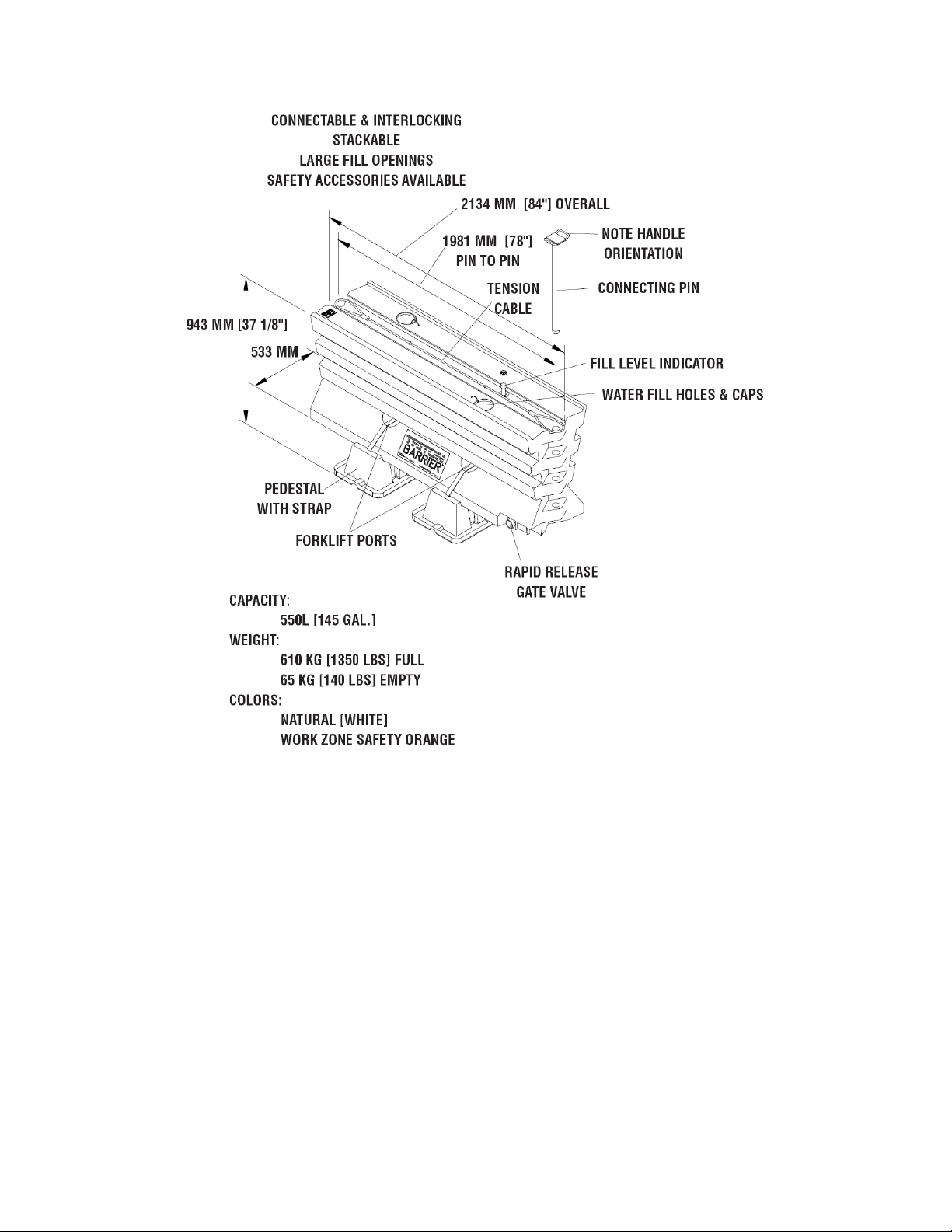
The Triton Barrier®system was tested to meet the impact criteria, requirements, and guidelines
of NCHRP Report 350. These tests, specifically set forth by FHWA, evaluate product
performance by simulating those impacts outlined by NCHRP Report 350 involving a typical
range of vehicles on our roadways, from lightweight cars (approx. 820kg [1800 lb.]) to full size
pickup trucks (approx. 2000 kg [4400 lb.]) as specified by the FHWA. A product can be certified
for multiple Test Levels. The Triton Barrier®is certified to the Test Level(s) as shown below:
Test Level 2: 70 km/h [44 mph]
Test Level 3: 100 km/h [62 mph]
These FHWA directed tests are not intended to represent the performance of systems
when impacted by every vehicle type or every impact condition existing on the roadway.
This system is tested only to the test matrix criteria of NCHRP 350 as approved by
FHWA.
Valtir does not represent nor warrant that the results of these controlled tests show that vehicle
impacts with the products in other conditions would necessarily avoid injury to person(s) or
property. Impacts that exceed the specifications of the system may not result in acceptable
crash performance as outlined in NCHRP Report 350, relative to structural adequacy, occupant
risk, and vehicle trajectory. Valtir expressly disclaims any warrant or liability for injury or damage
to persons or property resulting from any impact, collision, or harmful contact with products,
other vehicles, or nearby hazards or objects by any vehicle, object or person, whether or not the
products were assembled by third parties.
The Triton Barrier®system is intended to be deployed, delineated, and maintained in
accordance with specific state and federal guidelines. Valtir offers a reflective delineator panel
and has reflective tabs for its Triton Barrier®line of products. However, the material is only
intended to supplement delineation required by the Department of Transportation’s “Manual on
Uniform Traffic Control Devices” (MUTCD). Design tables are provided in this Manual to aid in
selecting the most appropriate product configuration for proper application to the site. The
appropriate highway authority approved engineer shall be careful to properly select, deploy, and
maintain the product. Careful evaluation of the site geometry, vehicle population type, speed,
traffic direction, and visibility are some of the elements that require evaluation for the proper
selection of a safety appurtenance by the appropriate specifying highway authority.
After an impact occurs, the product must be repaired to its original condition as soon as
possible. When a safety product is impacted, it is mandatory that the highway authority inspect
all the components for damage and replace/repair components as necessary. If the system is
not repairable, a complete system replacement is required. All replacement parts and
components for this system should be obtained from Valtir. No other part(s) should be
substituted or modified in any way to repair this product.

www.Valtir.com 7 Revision C February 2023
Important Introductory Notes
Proper deployment and maintenance of the Triton Barrier®system is critical to achieve
performance under appropriate state and federal guidelines. Take the time to review this
Manual, including the Limitations and Warnings section thoroughly, before performing the
necessary work. Do not attempt to assemble any longitudinal Triton Barrier®without the proper
plans and assembly Manual from the manufacturer.
If you require additional information, or have questions about the Triton Barrier®, please contact
Valtir Customer Service Department. See Customer Service Contacts on page 3 of this Manual.

www.Valtir.com 8 Revision C February 2023
Figure 1
Triton Barrier
®
TL-2 Components
813 MM
533 MM
1981 MM
2134 MM

www.Valtir.com 9 Revision C February 2023
Figure 2
Triton Barrier
®
TL-3 Components

www.Valtir.com 10 Revision C February 2023
Figure 3
TRITON BARRIER
®
TL-2 assembly (70 km/h [45 mph]
Figure 4
TRITON BARRIER
®
TL-3 assembly (100 km/h [62 mph])
TRITION BARRIER SECTION
PART NUMBERS
WHITE PART NUMBER
604926B
ORANGE PART NUMBER
604922B
TRITION TL-3 KIT
PART NUMBER 616243B

www.Valtir.com 11 Revision C February 2023
Special Site Considerations
A traffic control plan, in detail appropriate to the complexity of the work project, shall be
prepared and understood by all parties before Triton Barrier®is deployed in a work zone.
Some special site considerations are:
1. What is the intended speed at the site? The Triton Barrier®(TL-3) is capable of handling
impacts from vehicles up to 2000 kg [4400 lbs.] at speeds up to 100 km/h [62 mph] at
angles up to 25 degrees. The Triton Barrier®without pedestal (TL-2) is capable of
handling impacts from vehicles up to 2000 kg [4400lb] at 70 km/h [45 mph] and angles
up to 25 degrees.
LENGTH OF DEPLOYMENT
WATER REQUIRED
30m [100 ft.]
8235 liters [2175 gal]
40m [130 ft.]
10,980 liters [2900 gal]
50m [165 ft.]
13,725 liters [3625 gal]
60m [195 ft.]
16,470 liters [4350 gal]
70m [230 ft.]
19,210 liters [5075 gal]
80m [260 ft.]
21,955 liters [5800 gal]
90m [295 ft.]
24,700 liters [6525 gal]
100m [330 ft.]
27,445 liters [7250 gal]
150m [490 ft.]
41,170 liters [10,875 gal]
200m [655 ft.]
54,890 liters [14,500 gal]
2. What is the length of deployment? A minimum length of Triton Barrier®is needed
upstream and downstream of area being shielded to ensure proper impact performance.
The minimum length will depend on the specified speed of the roadway. For 70 km/h [43
mph] the minimum overall length is 30 m [100’]. For 100 km/h [62 mph] the minimum
overall length is 60m [200’]. Refer to the Length of Need (LON) section of the Triton
Barrier®Product Description Manual for more information.
3. Is an End Treatment warranted for the exposed or flared end of Triton Barrier®? If so, an
appropriate End Treatment must be attached. Refer to the End Treatment section of this
Manual on Page 17.
4. What is the lateral offset? As a general rule, a roadside barrier shall be placed as far
from the traveled way as conditions permit. The barrier-to-hazard clearance to shield
rigid objects, equipment, embankments, drop-offs, work crews, etc. shall not be less
than the lateral deflection of the barrier. See Deflection Chart section of this Manual on
Page 25.
5. What foundation will the barrier be deployed on and what is its slope? Triton Barrier®
may be deployed on various surfaces. Foundations other than clean asphalt may result
in varying lateral deflection for full design capacity impacts. See Deflection Chart section
of this Manual on Page 25. The existence of cross slopes greater than 5% or curbs may
create an untested effect on the impacting vehicle.
6. How will the barrier be deployed: (1) as a median barrier, (2) in a bidirectional traffic
situation, or (3) a road side application? Proper consideration must be given to Triton
Barrier®lateral deflection and End Treatment requirements to minimize the potential of
secondary impacts.
7. Can the water ballast be drained at the site? If not, provisions must be made to either
siphon out the water ballast or use a forklift to move full sections to a location where they
can be drained.

www.Valtir.com 12 Revision C February 2023
8. Will the barrier be used in a climate where the water ballast may freeze? The
performance of the barrier is not degraded if the water ballast freezes. However,
provisions should be made to handle the full weight of the barrier if this occurs. See
Other Design considerations section of Triton Barrier®Product Description Manual for
more information.
Preparation
Begin preparing for the assembly by reviewing the specified barrier location, layout, and
orientation. Determine the number of sections needed (See Length of Need section of the Triton
Barrier®Product Description Manual for more information). (When connected the pin to pin
distance of each section is approximately 2m [78”] long).
Caution: The minimum assembly length is 30 sections for TL-3 (100 km/h [62
mph]), and 15 sections for TL-2 (70 km/h [43 mph]).
Conduct a parts inventory check to make sure all the necessary components are available
before proceeding to the site. Visually check the sections for damage to ensure that they will
hold water.
Recommended Tools and Equipment
For a typical assembly the recommended tools and equipment are:
•Triton Barrier®Manual
•Application and/or traffic control plan (as required)
•Traffic control equipment (as required)
•Triton Barrier®components
•Transport truck
•Water truck w/pump*
•Sledge hammer
•Pry bar
•Generator (power for optional accessories)
•Forklift (optional)
∗A pump with 950-1135 liter/min. [250-300 GPM] output and a 75 mm [3”] dia. minimum x
15-30m [50-100’] long hose with a shutoff control has been shown to be efficient. Time
to fill one barrier is approximately 30 seconds.
Note: The above list of tools is a general recommendation. Depending on specific site
conditions and the complexity of the assembly specified by the appropriate highway
authority, additional or fewer tools may be required. Decisions as to what tools are
needed to perform the job are entirely within the discretion of the specifying highway
authority and the authority’s selected contractor performing the assembly of the system
at the authority’s specified site.

www.Valtir.com 13 Revision C February 2023
Deployment and Retrieval
1. A flatbed truck with a low bed is ideal for transporting Triton Barrier®. Load the sections
onto the transport truck to stack and position them for the greatest shipping density.
Secure the load before transport.
Note: Empty sections without pedestals may be stacked up to three high. Empty sections with
pedestals attached may be stacked two high. Filled sections shall not be stacked.
2. Begin deployment at the upstream traffic end of the site and work downstream. Work
from the non-traffic side of the deployment whenever possible. Unload the sections
taking care not to damage them. Unloading proceeds much faster if one person remains
on the truck and two people work on the ground. If site conditions permit, a fourth person
can drive the truck so that sections can be unloaded continuously as the deployment is
progressing.
3. If TL-3 kits (Pedestals) are used, attach Pedestals to the barrier using a strap as shown
in Figure 5 and Assembly drawing.
Figure 5
TRITON BARRIER
®
TL-3 STRAP

www.Valtir.com 14 Revision C February 2023
4. If used as a TL-3 End Treatment, the first segment is attached upside down, with the
Steel Pedestal attached. Using the pedestal as a template, drill 1/2” holes – 4 places as
shown. Attach short pedestal to surface of first section using 3/8” nuts, lock washers,
bolts and bar washers (See Figure 6 & View A-A). Use fill port as access hole. Invert
before attaching to other sections.
5. Align the sections according to the specified configuration and layout in the traffic control
plan.
Caution: Refer to deflection graph when determining minimum clearance
between barrier and hazard.
Caution: The existence of any cross-slopes in excess of 5% (3 deg.) or curbs
may create an untested effect on the impacting vehicle.
6. Triton Barrier®sections are not symmetrical. Pay special attention to the location of the
rapid release gate valve and fill level indicator. The rapid release gate valve should
usually be oriented on the side opposite traffic. Reflectors or reflective sheeting may be
attached as called for in the traffic control plan.
Bring the sections together and insert a connecting pin through the Top Cables and into
the overlapping End Knuckles at each joint. Push the pin in until it is flush with the top of
the sections. Take care to orient the handle on the pin so that the handle is
perpendicular to the length of the barrier.
Remove the fill level indicator decal.
Warning: Each joint must be connected with a pin or improper impact
performance will result. Barrier must not be used if steel cable is damaged or
missing.
View A-A
Figure 6
Cutaway View
(Shown right side up for clarity)

www.Valtir.com 15 Revision C February 2023
7. Completely fill each section with water. In End Treatment applications, the first section
remains empty.
Warning: Sections must be filled with water to ensure proper impact
performance.
If it is desirable in colder climates that the water not freezes, and in consideration of local
restrictions or regulations, add antifreeze as necessary. See the Triton Barrier®Product
Description Manual for additional information
Since filling the sections typically takes longer than deployment, it is convenient to have
a water truck available as soon as deployment begins. The water truck can follow
immediately behind the deployment crew to minimize time in the work zone. Filling
proceeds more quickly if one worker drives the water truck and another moves the fill
hose from section to section.
8. Place caps in fill holes.
9. If an End Treatment is specified for the layout, follow the instructions provided by the
manufacturer and attach it at this time. If the Triton Barrier®is acting as its own End
Treatment: For TL-3 (100 km/h [62 mph]) assemblies, the first barrier section must be
turned upside down, empty, strapped to a short pedestal, and the pin must be removed
from the exposed end; For TL-2 (70 km/h [45 mph]) assemblies, the first barrier section
must be empty and the pin must be removed from the exposed end.
Caution: An appropriate End Treatment must be attached where warranted to
ensure proper impact performance.
10. Deployment is now complete. Take the time to double-check the assembly as indicated
in the next section.

www.Valtir.com 16 Revision C February 2023
Checking the Assembly
Check the assembly to ensure that all sections are properly aligned, full of water ballast, and not
leaking. All fill level indicators should be up. If any are not up, check to see if the decals used for
shipment are still in place and remove them. Make sure that all cables are present and all pins
are inserted. If for some reason a section needs replacement, refer to the Maintenance and
Repair section of this Manual on Page 20.
Retrieval
1. Begin retrieval at the downstream traffic end of the site and proceed upstream. Begin the
retrieval procedure by removing the water ballast. If site conditions permit, the quick
release gate valve may be opened to allow the water to drain. Insert the protective fill
level indicator caps.
Note: The time it takes to drain a barrier section is approximately 4 1/2 minutes.
Caution: Water on the traveled roadway may create a slippery surface for
vehicles. Proper traffic control shall be deployed.
If the water may not be drained at the site, then the water may either be siphoned out or
the section can be unpinned and moved by forklift to another work area or site where it
may be drained or stored.
Caution: Do not use tension cables to lift barrier(s).
2. Once the water is removed, the pins may be removed and the sections separated.
3. Remove the empty sections onto the transport truck in the reverse order as they were
deployed. Secure the load before transport.
Storing
When storing the Triton Barrier®, be sure to leave the gate valve open or store upside
down.
Note: Empty sections may be stacked. Filled sections may not be stacked.

www.Valtir.com 17 Revision C February 2023
End Treatment
TL-3 100 km/h [62 mph]
The Triton Barrier®TL-3 has been thoroughly tested to NCHRP 350 TL-3 Non-Redirective
Gating conditions. The End Treatment has also been thoroughly tested for 100 km/h [62 mph]
when assembled as shown to the NCHRP 350 standard.
The Triton Barrier®TL-2 End Treatment has been tested to NCHRP 350 TL-2 Non-redirective
Gating conditions. It has proven for 70 km/h [43 mph] impact speeds when deployed as shown.
Figure 8
Triton Barrier®End Treatment
Figure 7
Triton Barrier®End Treatment placement

www.Valtir.com 18 Revision C February 2023
End Treatment Configuration (TL-3)
Notes:
1. Fill all sections except the first section with water. First section is to be upside down. Do
not use a connecting pin on the exposed end of the first section.
2. Vehicle trajectory will be biased toward the flare side of a flared configuration.
3. All sections are to have pedestals strapped to the bottom. The first section uses a short
pedestal.
End Treatment Configuration (TL-2)
Notes:
1. Fill all sections except the first section with water. Do not use a connecting pin on the
exposed end of first section.
2. Vehicle trajectory will be biased toward the flare side of a flared configuration.
Figure 10
Triton Barrier®(TL-2) 70 km/h [45 mph] End Treatment Placement
Figure 9
Triton Barrier®TL-3 100 km/h [62 mph] End Treatment

www.Valtir.com 19 Revision C February 2023
Figure 11
Triton Barrier®fill capacity chart
This manual suits for next models
1
Table of contents
Other VALTIR Control System manuals