vanEssen Diver-MOD-AS339 User manual

PRODUCT MANUAL
Diver-MOD – AS339
M-11118002E
Nijverheidsstraat 30,
6987 EM Giesbeek, The Netherlands
T+31 313 880 200
Einfo@eijkelkamp.com
Iwww.eijkelkamp.com

© July 2017 Van Essen Instruments. All rights reserved.
Contact details:
Copyright © 2017 by Van Essen Instruments B.V. All rights reserved. This document contains
proprietary information which is protected by copyright. No part of this document may be
photocopied, reproduced, or translated to another language without the prior written consent of
Van Essen Instruments B.V.
Van Essen Instruments B.V. makes no warranty of any kindwith regard to this material, including,
but not limited to, its fitness for a particular application. Van Essen Instruments B.V. will not be liable
for errors contained herein or for incidental or consequential damages in connection with the
furnishing, performance, or use of this material. In no event shall Van Essen Instruments B.V. be
liable for any claim for direct, incidental, or consequential damages arising out of, or in connection
with, the sale, manufacture, delivery, or use of any product. Van Essen Instruments and the Van
Essen Instruments logo, Diver are trademarks or registered trademarks Van Essen Instruments B.V.
The presence of the Waste Electrical and Electronic Equipment (WEEE) marking on the product
indicates that the device is not to be disposed via the municipal waste collection system of any
member state of the European Union.For products under the requirement of WEEE directive
(2012/19/EU), please contact your distributor or local Van Essen InstrumentsB.V. office for the
proper decontamination information and take back program, which will facilitate the proper
collection, treatment, recovery, recycling, and safe disposal of the device.
Nijverheidsstraat 30,
6987 EM Giesbeek, The Netherlands
T+31 313 880 200
Einfo@eijkelkamp.com
Iwww.eijkelkamp.com

© July 2017 Van Essen Instruments. All rights reserved.
CE COMPLIANCE STATEMENT (EUROPE)
We hereby declare that the device(s) described below are in conformity with the directives listed. In
the event of unauthorized modification of any devices listed below, this declaration becomes
invalid.
Type: Diver interface
Product Model: Diver-MOD (AS399)
Relevant EC Directives and Harmonized Standards:
1999/5/EC R&TTE Directive for Radio and Telecommunications Terminal Equipment in accordance
to annex III to which this directive conform to the followingstandards:
Low Voltage Directive per EN60950-1 (2006)+A11 (2011) for Product Safety testing
standard for "Information Technology Equipment"
EMC Directive EN 301 489-1 V1.8.1 / EN 301 489-17 V1.3.2 Electromagnetic emission and
immunity for "Information Technology Equipment"
2004/108/EC Electromagnetic Compatibility directive, as amended by EN61326-1:2013
The product(s) to which this declaration relates is in conformity with the essential protection
requirements of 2004/108/EC Electromagnetic Compatibility directive. The products are in
conformity with the followingstandards and/or other normative documents:
EMC: Harmonized Standards: EN 61326-1:2013 Lab Equipment, EMC
IEC61000-6-3:2007 Emission standard for residential, commercial and light-industrial
environments
IEC61000-4-2:2009 Electrostatic discharge immunity test
IEC61000-4-3:2006 Radiated, radio-frequency, electromagnetic field immunity test
IEC61000-4-4:2012 Electrical fast transient/burst immunity test
IEC61000-4-5:2006 Surge immunity test
IEC61000-4-6: 2014 Immunity to conducted disturbances, induced by radio-frequency fields
IEC61000-4-11:2004 Voltage dips, short interruptions and voltage variations immunity tests
I hereby declare that the equipment named above has been designed to comply with the relevant
sections of the above referenced specifications. The items comply with all applicable Essential
Requirements of the Directives.

© July 2017 Van Essen Instruments. All rights reserved.
Contents
1 Introduction.............................................................................................................................................1
1.1 Features..........................................................................................................................................1
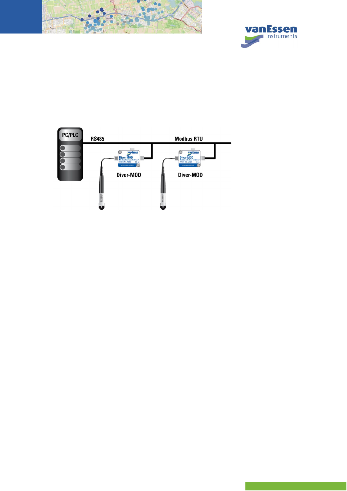
1.2 System Overview...........................................................................................................................2
2 Getting Started........................................................................................................................................2
2.1 Supported Equipment..................................................................................................................2
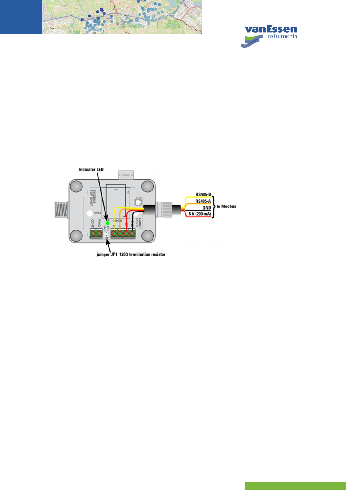
2.2 Installation.....................................................................................................................................3
2.3 Configuration.................................................................................................................................3
2.4 Transmission Mode.......................................................................................................................5
2.5 Operation.......................................................................................................................................5
3 Modbus Registers ....................................................................................................................................5
3.1 Reg. 30002, 30012: Firmware Version and Serial Number Diver-MOD.....................................5
3.2 Reg. 30220: Real-time Barometric Data from Diver-MOD.........................................................6
3.3 Reg. 40001: Change Slave Address of Diver-MOD ......................................................................6
3.4 Reg. 40002: Change Baudrate of the RS485 port .......................................................................6
3.5 Reg. 40003: Change Parity of the RS485 port.............................................................................7
3.6 Reg. 00001: Update Real-Time Data from Diver.........................................................................7
3.7 Reg. 00002: Get Diver Data ...........................................................................................................8
3.8 Reg. 00003: Update General Diver Information .........................................................................8
3.9 Reg. 00004: Force to accept new connected Diver ....................................................................8
3.10 Reg. 00011: Start/Stop Logging of Diver.....................................................................................9
3.11 Reg. 30241: Number of Records Recorded by Diver ..................................................................9
3.12 Reg. 30242: Maximum Number of Records for Diver.................................................................9
3.13 Reg. 30243: Remaining Battery Capacity Diver..........................................................................9
4 Reading Diver Data................................................................................................................................10
4.1 Header Information ....................................................................................................................10
4.2 Time Series Data..........................................................................................................................11
5 Appendix A – Specifications.................................................................................................................15
5.1 Casing...........................................................................................................................................15
5.2 Connections.................................................................................................................................15
5.3 Power Consumption...................................................................................................................15
5.4 Modbus.........................................................................................................................................15
5.5 Pressure........................................................................................................................................16
5.6 Temperature................................................................................................................................16
5.7 Environmental.............................................................................................................................16
6 Appendix B - Diver-MOD Register Map................................................................................................17
6.1 Coils – Status Registers...............................................................................................................17
6.2 Read Only Registers ....................................................................................................................17
6.3 Reading Diver Memory................................................................................................................18
7 Appendix C – Pressure Conversion Table ...........................................................................................22
8 Appendix D – Diver Equipment............................................................................................................23
8.1 Communication Cable................................................................................................................23
8.2 TD-Diver........................................................................................................................................23

© July 2017 Van Essen Instruments. All rights reserved.
8.3 Baro-Diver....................................................................................................................................24
8.4 Cera-Diver.....................................................................................................................................24
8.5 Micro-Diver...................................................................................................................................25
8.6 CTD-Diver .....................................................................................................................................25
8.7 Mini-Diver.....................................................................................................................................26
8.8 Baro-Diver....................................................................................................................................26

© July 2017 Van Essen Instruments. All rights reserved.
1
1 Introduction
The Diver-MOD is a Modbus interface for Divers and can be used to connect Divers to a RS485
network using the Modbus/RTU protocol. The Diver-MOD features a barometric sensor, which can be
used to convert the Diver pressure in to a water level.
The Diver-MOD is shown in Figure 1. The Diver-MOD casinghas an M12 connector (left) and a cable
gland (right) and an air vent with a Gore-Tex® membrane. The M12 connector on the left is
connected to a Diver communication cable (part no. AS2xxx) that on its turn is connected to a Diver
(DI5xx, DI6xx, DI7xx, DI8xx, DI27x).
Figure 1 top view of the Diver-MOD (part no AS339).
The cable gland on the right side of the casing is used to connect the Diver-MOD to the Modbus
interface through a 4-conductor cable. This cable is used for power supply and data transfer.
The air vent ensures that the pressure inside the casing is equal to the outside air pressure. The
built-in barometric pressure sensor allows to convert Diver pressure data into water level data.
1.1 Features
The Diver-MOD™ features:
Real-time Diver pressure, temperature and conductivity* data.
Real-time barometric pressure and temperature data.
Reading the Diver memory.
Programming of the Diver sample interval, setting the Diver clock, etc.
Starting/stopping of the Diver.
(* CTD-Diver DI27x only)
The Diver-MOD contains a barometric sensor, but has no built-in datalogger to store the barometric
data. Compensated pressure is not available as this can be done by the back-end software.
This manual outlines all the features and operating principles of the Diver-MOD. The next chapter
gives an overview of the supported equipment, installation procedures and configuration.

© July 2017 Van Essen Instruments. All rights reserved.
2
1.2 System Overview
A typical Modbus configuration is depicted in Figure 2. In the schematic two Diver-MODs are
connected to a PC/PLC. This connection includes both data communication and power. The
maximum Modbus cable length depends on the baud rate,the cable (gauge, capacitance or
characteristic impedance), the number of loads on the daisy chain, and the network configuration
(2-wire or 4-wire). For a maximum baud rateof 9600 and AWG26 or wider gauge, the maximum
length is 1000 meters.
Figure 2 example Modbus network with PC/PLC and2 Diver-MODs.
Each Diver-MOD is connected to a Diver through a Diver communication cable. The maximum length
of the Diver communication cable is 500 meters.
Each Diver-MOD must be programmed with a unique address (0 to 247). Messages sent to the
address 0 will be accepted by all Diver-MODs. The Diver-MOD acts as a slave for the PLC/PC that
requests the data from each Diver-MOD.
Up to 8 Diver-MODs can be used per Modbus network. TheDiver-MOD is powered by the Modbus
network. Each Diver-MOD is equipped with a 120 (1/4 W) termination resistor that can be used by
applying the termination jumper.
The Diver-MOD is in accordance with the Modbus Application Protocol Specification V1.1b3 and
enables to interface Divers in a RS485 network using the Modbus/RTU protocol. The Modbus TCP/IP
is not supported.
2 Getting Started
2.1 Supported Equipment
The Diver-MOD can be connected to a Diver via a Diver Cable AS2xxx using the M12 connector. The
following Divers can be used with the Diver-MOD:
TD and Baro-Diver (model DI8xx),
Mini and Baro-Diver (model DI5xx),
Micro-Diver (model DI6xx),
Cera-Diver (model DI7xx), and
CTD-Diver (model DI27x).
Detailed information about supported equipment can be found in Appendix D.

© July 2017 Van Essen Instruments. All rights reserved.
3
2.2 Installation
Connect the Diver-MOD to a Diver through a Diver communication cable (AS2xxx). Connect the Diver
communication cable to the Diver-MOD by attaching it to the M12 connector.
Connect the PC or PLC to the Diver-MOD using a 4-conductor cable. The 4-conductors are for
5 to 12-volt power supply
ground
RS485-A
RS485B
Feed the Modbus communication and power supply cable into the enclosure through the cable
gland and connect the wires as depicted in Figure 3. The cable gland provides an IP67 sealing for
Modbus cables with a diameter from 3.5 to 7 mm.
Figure 3 Diver-MOD connection to Modbus/RTU (cable colorsmay vary).
The Diver-MOD must be externally powered with +5VDC or +12VDC (4.75 Volt to 13.5 Volt). During
communication the peak current is 50 mA and the effective current is 20 mA. The stand-by current of
the Diver-MOD is 2 mA.
If the Diver-MOD is the last device in the RS485 network, the A and B line should be terminated with a
120 termination resistor. This can be done by placing jumper JP1, see Figure 3.
There is one signal indicator (LED) which will light up briefly when the Diver-MOD is powered on. In
addition, the LED will blink when there is activity on the RS485 communication line. When the Diver-
MOD is in standby, the LED will be off.
2.3 Configuration
Diver-MOD is designed to communicate on a Modbus network using RTU (Remote Terminal Unit)
mode. The ASCII (American Standard Code for InformationInterchange) mode is not supported by
the Diver-MOD.
The default serial settings are 9,600 bps, no parity and 1 stop bit. If the serial settings are changed by
Modbus function codes, the changes take place after repowering.
The default Diver-MOD address is 1. If the slave address is changed by Modbus function codes, the
change takes place immediately.

© July 2017 Van Essen Instruments. All rights reserved.
4
The master issues a Modbus request to the slaves in two modes:
In unicast mode, the master addresses an individual slave. After receiving and processing
the request, the slave returns a message (a 'reply') to the master. In that mode, a Modbus
transaction consists of 2 messages: a request from the master, and a reply from the slave.
Each slave must have a unique address (from 1 to 247) so that it can be addressed
independently from other nodes.
In broadcast mode, the master can send a request to all slaves. No response is returned to
broadcast requests sent by the master. The broadcast requests are necessarily writing
commands. All devices must accept the broadcast for writing function. The address 0 is
reserved to identify a broadcast exchange.
The Modbus RTU frame format for the Diver-MOD is shown in Figure 4. The client that initiates a
Modbus transaction builds the Modbus Protocol Data Unit (PDU) represented by the green blocks in
Figure 4, and then adds the address and error check(CRC) to build the appropriate communication
PDU.
A master addresses a slave by placing the slave address in the address field of the message. When
the slave returns its response, it places its own address in the response address field to let the
master know which slave is responding.
The function code indicates to the server what kind of action to perform. The function code can be
followed by a data field that contains request and response parameters.
All Diver-MOD commands contain checksum information (CRC), to enable detection of transmission
errors. Error checking field is the result of a "Redundancy Checking" calculation that is performed on
the message contents. The Diver-MOD uses the RTU calculation method for the CRC.
Details about the different fields of the Modbus frame for the Diver-MOD can be found in Table 1. The
Diver-MOD interface supports the function codes listed in Table 2.
Figure 4 Modbus message frame for the Diver-MOD on a serial line.
Table 1 Diver-MOD frame format.
Name Length (bits) Function
Start 28 At least 3½ characters times of silence (mark condition)
Address 8 Slave address
Function 8 Indicates the function code; e.g., read coils/inputs
Data N × 8 Data + length will be filled depending on the message type
CRC 16 Checksum
End 28 At least 3½ character times of silence between frames

© July 2017 Van Essen Instruments. All rights reserved.
5
Table 2 Diver-MOD function codes.
Function name Function code Function type
Read Coils 0x01 (decimal 1) Internal Bits or Physical Coils
Write Single Coil 0x05 (decimal 5) Internal Bits or Physical Coils
Read Input Registers 0x04 (decimal 4) Physical Input Registers
Read Holding Registers 0x03 (decimal 3) Internal Registers or Physical Output Registers
Write Single Register 0x06 (decimal 6) Internal Registers or Physical Output Registers
Write Multiple Registers 0x10 (decimal 16) Internal Registers or Physical Output Registers
2.4 Transmission Mode
The format for each byte (11 bits) for the Diver-MOD is:
Coding System: 8–bit binary
Bits per Byte: 1 start bit
8 data bits, least significant bit sent first
1 bit for parity completion
1 stop bit
2.5 Operation
The Diver-MOD acts as an interface between the Diver anda Modbus network, i.e. it converts the
Modbus commands to Diver commands and vice-versa. There is no direct communication between
the Modbus supervisory computer and the Diver. The Diver-MOD acts as a buffer between the
supervisory computer and the Diver. For example, to get a real-time value from the Diver, first a
command must be sent from the supervisory computer to the Diver-MOD. Then the Diver-MOD will
retrieve the real-time values from the Diver and store them in its internal memory. Finally, the
supervisory computer can send a command to the Diver-MOD to retrieve the real-time values.
3 Modbus Registers
All the supported Modbus registers of the Diver-MOD are listed in Appendix B. A more detailed
description of themost important registers is given below. Refer to Table 2 for the definition of the
function code.
All registers in this document are 1-based.This means the actual packets sent to the Diver-MOD
must have a data address 1 less than what the register number is in this document.
3.1 Reg. 30002, 30012: Firmware Version and Serial Number Diver-MOD
The firmware version and serial number of the Diver-MOD are stored in register 30001 and 30011

© July 2017 Van Essen Instruments. All rights reserved.
6
Example:
Description Function
code Register Size
(registers)
Data
field Remark
1
Read firmware version of
Diver-MOD 0x04 30002 10 - Register 30002, convert to
string (20 characters).
2
Read serial number of
Diver-MOD 0x04 30012 10 - Register 30012, convert to
string (20 characters).
3.2 Reg. 30220: Real-time Barometric Data from Diver-MOD
The real-time data from the barometric sensor in the Diver-MOD is stored in register 30220 and
30230.
Example:
Description Function
code Register Size
(registers)
Data
field Remark
1
Read real-time values
barometric sensor (long) 0x04 30221 2 - Register 30221, convert to
longs (two registers for long).
2
Read real-time values
barometric sensor (float) 0x04 30231 2 - Register 30231, convert to
single float (two registers for
single float).
3.3 Reg. 40001: Change Slave Address of Diver-MOD
Register 40001 contains the slave address of the Diver-MOD. The default slave address is 1. The slave
address can be set from 1 to 247.
Example:
Description Function
code Register Size
(registers)
Data
field Remark
1
Change slave address 0x06 40001 1 <1-247> Data field is new address.
Register 40001 will take effect
immediately.
3.4 Reg. 40002: Change Baudrate of the RS485 port
Register 40002 contains the baudrate at which the Diver-MOD operates. The default baudrate is
9,600 bps. The data field must have a value from 1 to 8, which corresponds to the following
baudrate:
0 = 300 bps
1 = 1,200 bps
2 = 2,400 bps
3 = 4,800 bps
4 = 9,600 bps
5 = 19,200 bps
6 = 38,400 bps
7 = 57,600 bps
8 = 115,200 bps

© July 2017 Van Essen Instruments. All rights reserved.
7
Example:
Description Function
code Register Size
(registers)
Data
field Remark
1
Change baudrate 0x06 40002 1 <1-8> Register 40002, will take
effect after reboot (reset).
3.5 Reg. 40003: Change Parity of the RS485 port
Register 40003 contains the parity of the RS485 port. The default is no parity. The data field must
have a value from 0 to 3, which corresponds to the following parity:
0 = none
1 = even
2 = odd
3 = mark
Example:
Description Function
code Register Size
(registers)
Data
field Remark
1
Change parity 0x06 40003 1 <0-3> Register 40003, will take
effect after reboot (reset).
3.6 Reg. 00001: Update Real-Time Data from Diver
Setting this register forces the Diver-MOD to get real-timevalues, i.e. pressure, temperature and
conductivity (if applicable), from the connected Diver. The updated real-time values must be read
from registers 30201 – 30216.
The type of conductivity is either normal conductivity or specific conductivity at 25 °C depending on
the setting in the CTD-Diver.
Example:
Description Function
code Register Size
(registers)
Data
field Remark
1
Update real-time values
from Diver, i.e. copy
values to Diver-MOD
0x05 00001 1 0xFF00 Register 00001 can also be a
broadcast (address 0) to all
Diver-MODs. In case of a
broadcast, wait at least
500 ms before the next
instruction.
2
Read real-time values
from all channels (longs) 0x04 30201 6 - Register 3020x, convert to
longs (two registers per long)
3
Read real-time values
from all channels (float) 0x04 30211 6 - Register 3021x, convert to
single floats (two registers
per single float)
4
Go to step 1 When used in a loop

© July 2017 Van Essen Instruments. All rights reserved.
8
3.7 Reg. 00002: Get Diver Data
Setting this register will force the Diver-MOD to copy all recorded data from the connected Diver to
the Diver-MOD’s internal memory. After this the Diver data can be obtained using registers 30301 –
40000.
Example:
Description Function
code Register Size
(registers)
Data
field Remark
1
Instruct Diver-MOD to
copy recorded data from
the connected Diver
0x05 00002 1 0xFF00 Register 00002 can also be a
broadcast (address 0) to all
Diver-MODs.
2
Read Diver data See appendix C
3.8 Reg. 00003: Update General Diver Information
Setting this register forces the Diver-MOD to retrieve all general information from the connected
Diver. After this register is set, the latest recorded pressure and temperature measurements from
the Diver can be obtained from registers 30022 – 30243. This action is only needed when the Diver
settings are changed after powering up the Diver-MOD.
Example:
Description Function
code Register Size
(registers)
Data
field Remark
1
Instruct Diver-MOD to
update general
information from
connected Diver
0x05 00002 1 0xFF00 Register 00003, not required
if Diver was connected before
power up.
2
Read serial number of the
Diver 0x04 30022 18 - Register 30022, convert to
string (36 characters).
3
Read reference and
ranges from all channels
of the Diver
0x04 30101 6 - Register 30101, all integers
(one integer per register)
3.9 Reg. 00004: Force to accept new connected Diver
When the Diver-MOD is continuously powered, it will not automatically recognize if a Diver is
connected, replaced or reprogrammed. Setting register 00004 forces the Diver-MOD to connect to
the Diver. Any Diver data in the Diver-MOD memory will be erased and replaced by the data from the
newly connected Diver. Moreover, the Diver settings in the Diver-MOD will be refreshed.
Example:
Description Function
code Register Size
(registers)
Data
field Remark
1
Force the Diver-MOD to
update the settings and
data from the connected
Diver
0x05 00004 1 0xFF00 Not required if the Diver was
connected during power up.

© July 2017 Van Essen Instruments. All rights reserved.
9
3.10 Reg. 00011: Start/Stop Logging of Diver
Setting register 00011 to 0xFF00 will start logging of the Diver and setting this register to 0x0000 will
stop logging of the Diver.
Example:
Description Function
code Register Size
(registers)
Data
field Remark
1
Set the real-time clock of
the Diver 0x03 40103 6 YY,MM,D
D,
HH,MM,
SS
First register 40103 is YEAR
(YY)
2
Set the sample interval of
the Diver 0x03 40101 2 tt,xx FI: Register 40101 =01(tt) and
Register 40102=30(xx) gives
30 second sample interval
3
Set the monitoring point
name of the Diver 0x03 40109 10 20 chars Register 40109 - 40118
4
Start the Diver 0x05 00011 1 0xFF00 Register 11: 0xFF00 is start
3.11 Reg. 30241: Number of Records Recorded by Diver
This register contains the number of records recorded by the Diver. First set register 00001 to update
this register in the Diver-MOD with the most recent value.
Example:
Description Function
code Register Size
(registers)
Data
field Remark
1
Update settings from
Diver in Diver-MOD 0x05 00001 1 0xFF00
2
Read the number of
records recorded by the
Diver
0x04 30241 1 - Register 30241, integer value
from 0 to 48,000
3.12 Reg. 30242: Maximum Number of Records for Diver
This register contains the maximum number of records that can be recorded by the connected Diver.
Example:
Description Function
code Register Size
(registers)
Data
field Remark
1
Read the Diver’s memory
capacity in records 0x04 30242 1 - Register 30242, integer value
24,000 or 48,000 records
3.13 Reg. 30243: Remaining Battery Capacity Diver
This register returns the remaining battery capacity of the connected Diver as a percentage of its full
capacity. This value is only an indication! If the remaining battery capacity comes close to zero, the
Diver needs to be replaced to prevent lost data!

© July 2017 Van Essen Instruments. All rights reserved.
10
Example:
Description Function
code Register Size
(registers)
Data
field Remark
1
Read the remaining
battery capacity of Diver 0x04 30243 1 - Register 30243, integer value
0-100% remaining battery
capacity
4 Reading Diver Data
The data from the connected Diver is copied to the internal memory of the Diver-MOD. This is a
background process of the Diver-MOD. The update interval for this process can be set in register
00002. Because the data is stored in the Diver-MOD, the Diver data can be retrieved much faster from
the Diver-MOD than if it must be read from the Diver.
The Diver data consists of two parts: the header information and the time series data.
4.1 Header Information
The header information is stored in registers 30301 to 30481. The data is stored in ASCII. The header
information is required to obtain the time series data in engineering units. The header information
contains specific information about each parameter (channel) measured by the Diver, the Diver
serial number, the monitoring point name (location), etc.
The following data is required to obtain the time series data in engineering units.
Start Date/Time
The start date/time must be read from 9 registers starting at 30464. The returned string has the
following format:
ss:mm:HH dd/MM/yy
For example, the returned string is “00:00:01 10/08/15”, which equals 1:00:00 AM on August 10, 2015.
Sample Interval
The sample interval must be read from 7 registers starting at 30455. The returned string has the
following format:
DD HH:mm:ss f
Where DD is number of days and f is tenths of a second; f will be 0 or 5. For example, thereturned
string is “00 01:00:00 0”, which equals a sample interval of 1 hour.
Pressure Reference and Range
The pressure data is stored in channel 1. The unit of pressure is cmH2O (conventional). By definition
1 cmH2O equals 98.0665 Pascal.
The pressure reference is defined as the value (offset) in cmH2O from which the Diver starts
measuring pressure. For all supported Divers this is 400 cmH2O. The pressure reference can be read
from register 30101. The returned value is a signed 16 bit integer, for example “400”.

© July 2017 Van Essen Instruments. All rights reserved.
11
The pressure range is defined as the span of the pressure in cmH2O over which the Diver can
measure pressure. The pressure range can be read from register 30104. The returned value is a
signed 16-bit integer, for example “1750”.
The returned value depends on the water column that the Diver can measure. The Diver part
numbers and corresponding ranges are listed in Table 3.
Table 3 Divers and pressure range
Part No Water column /meter Range /cmH2O
DI500 1.5 750
DI501, DI601, DI701, DI271 10 1750
DI502, DI602, DI702 20 2750
DI505, DI605, DI705, DI272 50 5750
DI511, DI610, DI710, DI273 100 10750
Temperature Reference and Range
The temperature data is stored in channel 2. The unit of temperature is degree Celsius.
The temperature reference is defined as the value (offset) in degree Celsius from which the Diver
starts measuring temperature. For all the supported Divers this is -20 °C. The temperature reference
can be read from register 30102. The returned value is a signed 16-bit integer, for example “-20”.
The temperature range is defined as the span of the temperature in degree Celsius over which the
Diver can measure temperature. For all the supported Divers this is 100 °C. The temperature range
can be read from register 30105. The returned value is a signed 16-bit integer, for example “100”.
Conductivity Reference and Range
This section applies to the CTD-Diver only. The conductivity data is stored in channel 3. The unit of
conductivity is milli Siemens per centimeter (mS/cm).
The conductivity reference is defined as the value (offset) in mS/cm from which the CTD-Diver starts
measuring conductivity. For the CTD-Diver this is 0 mS/cm. The conductivity reference can be read
from register 30103. The returned value is a signed 16-bit integer, for example “0”.
The conductivity range is defined as thespan of the conductivity in mS/cm over which the Diver can
measure conductivity. This range can be adjusted by the user to (30, 120 or 300) mS/cm. The
conductivity range can be read from register 30106. The returnedvalue is a signed 16-bit integer, for
example “120”.
Note: If a regular Diver, i.e. not a CTD-Diver, is connected to the Diver-MOD the returned values for
the conductivity reference and range will be “0”.
4.2 Time Series Data
Each Diver data record consists of a timestamp, a pressure value, a temperature value and a
conductivity value (CTD-Diver only). Each Diver data record is stored in the Diver-MOD in 4 registers
as depicted in Figure 5.

© July 2017 Van Essen Instruments. All rights reserved.
12
Figure 5 A Diver data record is stored in four registers in the Diver-MOD memory
Timestamp
The first or time register has a value from 0 to 250. Only the first Diver data record will have a 0 for
the time register. The time register will be 1 if the Diver sample method is set to fixed or averaging.
For other sample methods, the time ranges from 1 to 250.
The timestamp of the first Diver data record is equal to the start time form the header information.
For each subsequent Diver data record the timestamp value can be calculated from:
Timestamp of previous Diver data record + sample interval × time register
Pressure
The second or pressure register has decimal values from 0to 30,000 (PDEC). Use the pressure
reference and range from the header information to convert these values to engineering units (PENG):
PENG = PDEC / 30000 × range + reference
If the pressure must be converted to a different unit then refer to Appendix C for conversion factors.
Temperature
The third or tempregister has decimal values from 0 to 30,000 (TDEC). Use the temperature reference
and range from the header information to convert these values to engineering units (TENG):
TENG = TDEC / 30000 × range + reference
Conductivity
The fourth or conductivity register has decimal values from 0 to 30,000 (CDEC). Use the pressure
reference and range from the header information to convert these values to engineering units (CENG):
CENG = CDEC / 30000 × range + reference
Time Series Data
The Diver time series data is stored in the Diver-MOD in memory blocks of 2,000 records each. The
memory block is selected by setting register 40041 from 0 to 35 in. Subsequently, the 2,000 records
from the specified block can be read from register 32001 to40000. A functional block diagram of this
workflow is shown in Figure 6.

© July 2017 Van Essen Instruments. All rights reserved.
13
Figure 6 Functional block diagram of how Diver data is stored in the Diver-MOD and can be accessed
Registers must be read until one or more registers contain the value 0xFFFF. The last Diver data
record is proceeded by 4 registers all containing 0xFFFF.
Example:
Description Function
code Register Size
(registers)
Data
field Remark
1
Read general header
information 0x04 30301 28 - Read 28 registers, starting at
register 30301, to get the
general header information.
2
Read channel 1 header
information 0x04 30329 24 - Read 24 registers, starting at
register 30329, to get the
channel 1 header
information.
3
Read channel 2 header
information 0x04 30371 24 - Read 24 registers, starting at
register 30371, to get the
channel 2 header
information.
4
Read channel 3 header
information 0x04 30413 24 - Read 24 registers, starting at
register 30413, to get the
channel 3 header
information. CTD-Diver only.
5
Read timing header
information 0x04 30455 27 - Read 27 registers, starting at
register 30455, to get the
timing header information.
6
Set block number to read 0x03 40041 1 j
<0-35>
Set register 40041 to select
the block number to read.

© July 2017 Van Essen Instruments. All rights reserved.
14
Description Function
code Register Size
(registers)
Data
field Remark
7
Read 2,000 Diver data
records 0x04 32001 8,000 - Read from register 32001 in
increments of 100 registers.
Stop reading if one or more
registers contain 0xFFFF.
8
Continue reading data
next 2,000 Diver records.
Go to step 6.
Increment j by 1.

© July 2017 Van Essen Instruments. All rights reserved.
15
5 Appendix A – Specifications
5.1 Casing
Dimensions (L × W × H) 65 mm × 50 mm × 35 mm
Weight ~82 g
Material ABS
Protection classification IP65
5.2 Connections
Diver Cable M12 connector (connect to AS2xxx cable)
Length: 0.5 to 500 meter
Modbus Cable Gland PG-7
Compatible Diver models Mini-Diver (DI5xx), Micro-Diver (DI6xx), Cera-Diver
(DI7xx), CTD-Diver (DI27x), TD-Diver (DI8xx)
5.3 Power Consumption
External supply voltage 5 to 12 V
Standby current 2 mA
Maximum current 10 mA
5.4 Modbus
Communication RS485 half-duplex, single pair, 300 bps to 115,200 bps
Multi-drop yes, max 8 devices per communication link
Address user programmable: 1 to 247
Modbus features: Real-time Diver conductivity (CTD-Diver only) pressure
and temperature reading.
Read Diver memory
Read/write Diver sample interval
Read/write monitoring point name of Diver
Start/stop Diver (no future start)
Read memory status: total memory and memory used
Table of contents