Vanguard 1442MMi User manual

Printed in the USA VGMNL062512-1400MMi
Operation Manual
Model 1442MMi
www.veegee.com | 800-423-8842

Vanguard 1442MMi Industrial microscopes are suited for
brightfield and simple polarization observation of industrial
applications such as semiconductor inspection, viewing of
metallographic specimens, and crystallographic analysis.
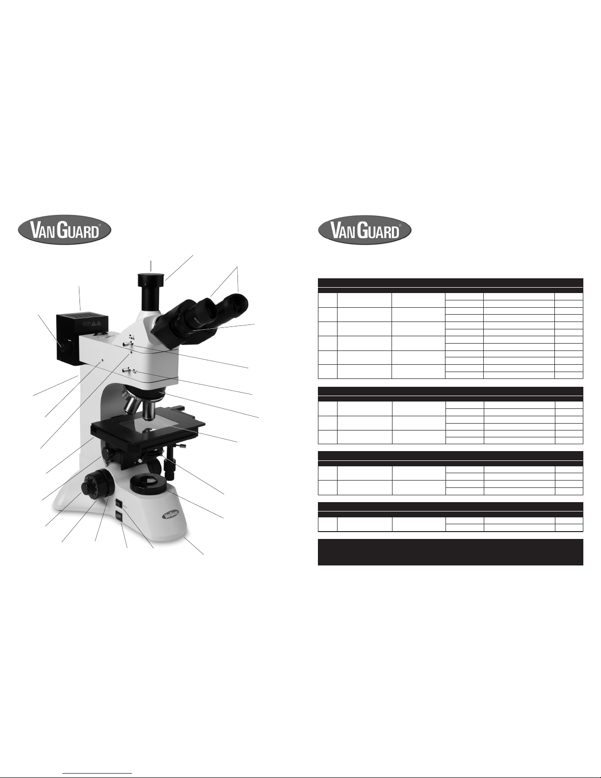
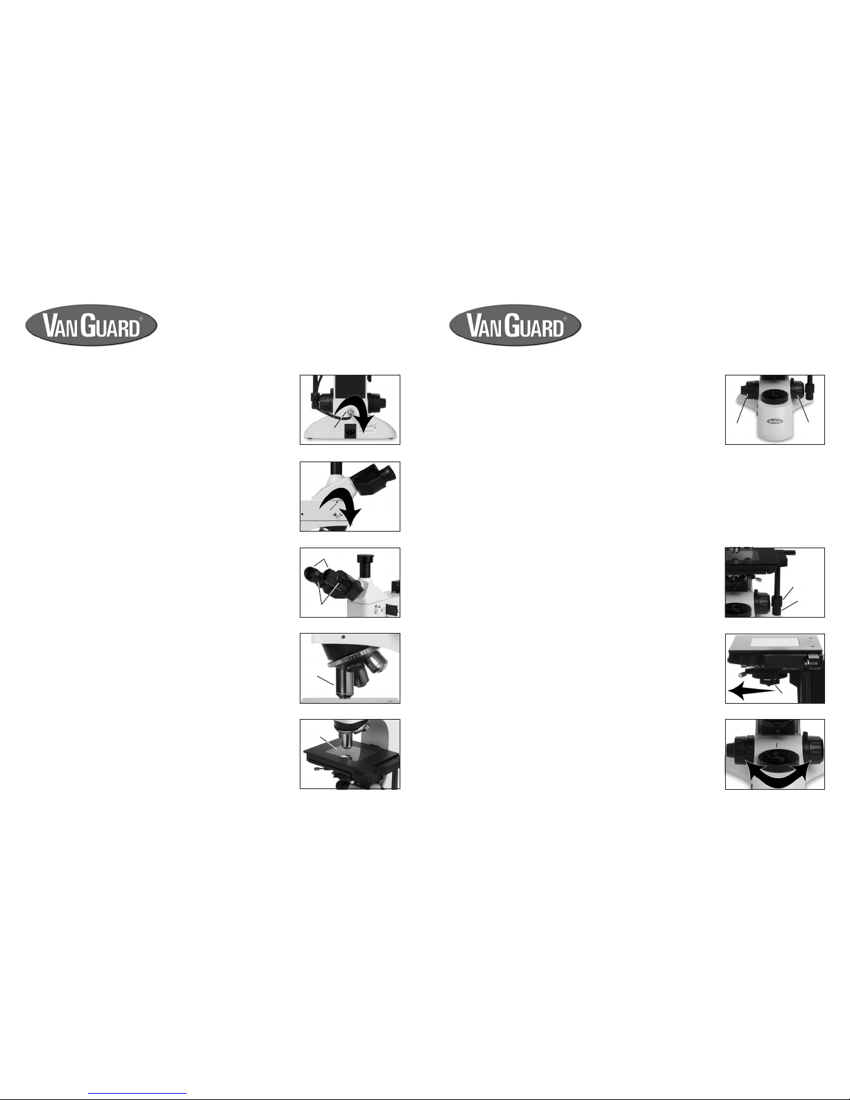
Viewing Head. Trinocular (Seidentopf) head is inclined at
30° and features interpupillary and dioptric adjustments. The
trinocular head features a sliding main prism with a 100/0
split.
Eyepieces. 10X ultra-widefield with a field number of 22.
Nosepiece. Quintuple, ball-bearing nosepiece with high-grade
lubricant for smooth operation, and positive stops.
Objectives. The Plan Achromatic, long working distance,
infinity corrected objectives are optically coated to reduce
unwanted reflections.
Stage. The mechanical stage measures 140mm x 185mm
and includes a removable 95mm x 75mm glass insert. Motion
of mechanical stage is controlled by a right-hand, low-position
coaxial control and is driven by a rack and pinion system.
Focusing movement. Coaxial, ultra-low position coarse and
fine focus controls feature a 30mm focusing range and are
graduated to 2 microns per division. Fitted with a tension
adjustment and stage limit control.
Transmitted Condenser. The 0.85 N.A. Abbe brightfield
condenser includes an iris diaphragm and swing-in lens.
Transmitted Illumination. 30W variable quartz halogen light
source. Comes with blue and dispersion filters. Also includes
filters for simple polarization.
Reflected Illumination. 50W variable quartz halogen light
source. Comes with blue, yellow, green, and dispersion filters.
Also includes filters for simple polarization.
Body. Cast-metal, ergonomic body with stain-resistant enamel
finish.
1442MMi Industrial Microscope
Thank you for purchasing this VanGuard microscope.
With the user in mind, VanGuard microscopes are
built from modern designs and should provide a
lifetime of reliable performance. Before using this
microscope it must be properly setup, which requires
some familiarity with the microscope. For this reason
we recommend you read this entire manual carefully
before setting up and using the instrument.
IntroductionIntroduction
Introduction
2
See included warranty card for more information.
Disclaimer:
The information provided in this operation manual is believed to be accurate and reliable at the time of printing. However, no responsibility shall be
assumed by VEE GEE Scientific for its use. The information contained in this document is subject to change without notification.
This product is designed and intended for use only as a microscope system. Modifying the product in any manner for use not originally intended shall
automatically void the manufacturer’s warranty. In no event shall VEE GEE Scientific, Inc. be held liable for any incidental or indirect damage arising
from the use of modified or altered product.
All rights reserved. No part of this document may be reproduced or transmitted in any form without the prior written consent of VEE GEE Scientific,
Inc.
©2012 VEE GEE Scientific, Inc.
5 Year Limited Warranty
VanGuard Microscopes are warranted by VEE GEE Scientific, Inc. to be free from defects in
material and workmanship for a period of five (5) years from the date of purchase, except for
electrical components which have a one (1) year limited warranty. During this period, VEE
GEE Scientific, or its authorized service station, will at their option and without charge, either
repair or replace any part found to be defective in materials or workmanship.
This warranty is subject to the following limitations and exceptions and will not apply if:
1) There is lack of proof of date and place of purchase. The purchase invoice must accom-
pany the unit when sent in for repair. The warranty extends to the original consumer pur-
chaser only and is not assignable or transferable.
2) The damage is due to normal wear and tear, misuse, abuse, negligence, accident, inad-
equate maintenance, disregard for operating instructions, or to any other cause not due to the
manufacture of the microscope (i.e. objective failure because of oil penetration due to lack of
timely cleaning).
3) The serial numbers, names, and/or functions are altered or obliterated; or unauthorized
repair or replacement of parts by the End-User or an unauthorized third party while under
warranty.
4) Consumable items (such as, but not limited to bulbs) have failed.
This warranty expressly excludes transportation damage and adjustment or readjustment. In
no case shall VEE GEE Scientific be liable to the Buyer or any person for any special, indirect,
incidental, or consequential damage whether claims are based in contract or otherwise with
respect to or arising out of product furnished hereunder. For goods manufactured by any
third party, VEE GEE Scientific’s liability under warranty is limited to the terms of the warranty
by the supplier for the goods. All warranty work shall be performed at the authorized service
center which is: National Microscope Exchange, Tel: (425) 788-2662. Contact your distribu-
tor or NME to discuss the problem and obtain instructions for the return of your microscope
for repair. The original purchaser returning this product must prepay all postage, shipping,
transportation, packaging, and delivery costs to NME.
www.veegee.com | 800-423-8842

General InformationGeneral Information
General Information
3
Table of Contents
Introduction........................................................ 2
Table of Contents.............................................. 3
Safety Information............................................. 3
Components
Microscope Diagram.................................. 4-7
Included Parts................................................ 8
Optional Accessories...................................... 8
Assembly
Unpacking Components................................. 9
Head & Reflected Illuminator Assembly.... 9-10
Objective Installation..................................... 10
Stage Plate Installation.................................. 10
Condenser Installation.................................. 11
Power Cord Installation................................. 11
Setup
Reflected Illumination Setup................... 12-13
Reflected Field Diaphragm Alignment..... 13-14
Eyecups........................................................ 14
Interpupilliary Adjustment.............................. 14
Focus Adjustment.......................................... 15
Focus Tension Adjustment............................. 15
Setup (continued)
Stage Limit...................................................... 15
Diopter Adjustment......................................... 15
Transmitted Illumination Setup................. 16-17
Kohler Illumination Setup......................... 17-18
Trinocular Camera Port Setup........................ 18
Microscope Use
Focusing & Mechanical Stage Mechanisms.... 19
Abbe Condenser Swing-In Lens..................... 19
Colored Filters - Transmitted.......................... 20
Colored Filters - Reflected............................. 20
Polarizer/Analyzer - Transmitted..................... 20
Polarizer/Analyzer - Reflected........................ 20
Maintenance
Replacing the Transmitted Illuminator Lamp... 21
Replacing the Reflected Illuminator Lamp...... 21
Replacing the Fuse......................................... 22
Caring for your 1442MMi Microscope............. 23
Troubleshooting........................................ 24-25
Specifications................................................. 26
Warranty Information..................................... 27
Attention - possible injury or product damage if instructions are not followed
Safety Symbols
Anytime you see the following symbols used in this manual pay special attention and follow the safety precautions.
Hot Surface - potential for burns if contact with hot surfaces are made
Shock Hazard - failure to follow instructions could lead to electrical shock
Safety Precautions
Before replacing the lamp or fuses always turn off the power switch and disconnect the power cord. Always
use the correct type and rated fuses. Using incorrect fuses could result in damage to the microscope and
electrical shock. Only use the supplied power cord and ensure that you are using a properly grounded outlet.
It is normal for the illuminator housing to get hot during use. Be careful to avoid touching the illuminator
housing until the unit has had sufficient time to cool after switching off.
SpecificationsSpecifications
Specifications
26
Viewing Head: Trinocular
Viewing Head Type: Seidentopf
Head Inclination: 30°
Sliding Prism for Trinocular Port: 100/0 Split
Interpupillary Adjustment: 55-75mm
Dioptric Adjustment: -5 to +5
Eyepiece Magnification: 10X High Eyepoint, Ultra-Widefield
Eyepiece Field Diameter: 22mm
Nosepiece: Quintuple, reverse facing
Brightfield Objectives: 5X [0.12 N.A., 26mm W.D.]
(Plan Achromatic, Infinity, LWD) 10X [0.25 N.A., 20mm W.D.]
20X [0.40 N.A., 9mm W.D.]
40X [0.60 N.A., 4mm W.D.]
Stage Dimensions: 140mm x 210mm
Stage Motion: Right-Hand Coaxial Control/Rack & Pinion Drive
Stage Movement Range: 752x 63mm
Focusing Movement: Coaxial Coarse & Fine Controls
Focusing Graduation: 2 microns Per Division
Brightfield Condenser: 0.85 N.A. Abbe Condenser with Iris Diaphragm
Transmitted Illumination: 30W, 12V Variable Quartz Halogen
Reflected Illumination: 50W, 12V Variable Quartz Halogen
Fuse: 3A, 250V
Voltage: 110V [Standard], 220V [Optional]
Base Dimensions: 280mm x 250mm
Overall Dimensions: 470mm (L) x 250mm (W) x 520mm (H)
Weight: 10kg

ComponentsComponents
Components
4
Lamp Housing
Lamp Focus
Knob
Eyepieces
with
Eyecups
Trinocular Port
Dust Cap
Trinocular Port
Diaphragm
Centering
Adjustment
(left)
Head Set
Screw
Prism Selector
Knob
Illumination
Selector Knob
Diopter
Adjustment
Objective
Turret
Mechanical
Stage
Substage
Control
Fine Focus
Control
Coarse
Focus
Control
Focus
Tension
Control
Power
Switch
Illumination
Selector Switch Base
Transmitted Illumination
Aperture Diaphragm
Glass Stage Insert
Transmitted Illumination
Field Diaphragm
TT
TT
Troubleshootingroubleshooting
roubleshootingroubleshooting
roubleshooting
25
For information about parts, accessories, or service -- contact your dealer directly
or contact VanGuard Microscopes at 1-800-423-8842.
Symptom: Can’t focus on specimen image
Step # Possible Cause How To Test Test Result? Solution For More Info
2
1Dirty objective Visually inspect
Objective is clean
Objective is not clean
Go to next step
Clean objective or replace with new objective Page 23
Stage limit set too low
Check position of stage limit by
loosening the control and adjusting
the focus
Stage limit set correctly
Set too low
Contact dealer or VanGuard Microscopes
Raise stage and set stage limit Page 15
Symptom: The stage keeps drifting downward
Step # Possible Cause How To Test Test Result? Solution For More Info
1Focus tension is set too loose Check focus tension control
Tension too loose
Tension set correctly
Increase tension
Contact dealer or VanGuard Microscopes
Page 15
Stand
Symptom: Image through eyepieces is too dim
Step # Possible Cause How To Test Test Result? Solution For More Info
1
2
Variable lighting control (VLC) is
turned down too far Visually inspect VLC is turned up
VLC is turned down
Go to next step
Turn VLC up Page 12, 16
Lamp not centered properly Visually inspect Lamp is centered
Lamp is not centered
Go to next step
Center the lamp Page 13, 17
3Dirty condenser, eyepiece, or
objective lenses Visually inspect Lenses are dirty
Lenses are clean
Clean condenser, eyepiece, or objective lenses
Contact dealer or VanGuard Microscopes
Page 23
Symptom: No image visable in eyepiece and/or trinocular port
Step # Possible Cause How To Test Test Result? Solution For More Info
1
6
4
3
2
Light is not switched on Visually inspect
Switched on
Not switched on
Go to next step
Move power switch to on position Page 12, 16
Variable lighting control (VLC) is set
too low Visually inspect
Not set too low
Set too low
Go to next step
Increase VLC level
Objectives not installed or turret is
set to empty position Visually inspect
Objectives are installed
Objectives not installed
Go to next step
Install objectives or change turret position Page 10
Prism selector knob in wrong
position Visually inspect
In correct position
Not in correct position
Go to next step
Set to correct position Page 11
Light path blocked (transmitted
illumination)
Visually inspect space between
illuminator and objectives Blockage present
Nothing blocking
Remove blockage
Contact dealer or VanGuard Microscopes
Page 18
Page 12, 16
5Illumination selector switch and/or
knob are set at incorrect positions Visually inspect
In correct position
Not in correct position
Go to next step
Set to correct position Page 12, 16

ComponentsComponents
Components
5
Trinocular Port
Set Screw
Reflected
Illumination
Analyzer Knob
Reflected
Illumination
Polarizer Slider
Diaphragm
Centering
Adjustment
(right)
X-Axis Lamp
Adjustment
Knob
Lamp
Housing
Door
Y-Axis Lamp
Adjustment
Knob
Lamp Housing
Power Cord
and Plug
Stage Limit
Main Power
Jack
Fuse Holder
Variable
Lighting
Control
Y-Axis
Stage
Control
Z-Axis
Stage
Control
Drop-In Colored
Filter Holder
Swing-In
Condenser Lens
Objectives
Head
Reflected
Illuminator
Reflected
Illuminator
Set Screw
TT
TT
Troubleshootingroubleshooting
roubleshootingroubleshooting
roubleshooting
24
This chart may help resolve some of the more common problems associated
with using a compound microscope. Simply follow the steps until your problem
is resolved. As always, you can contact your dealer or VanGuard Microscopes
if you ever need help.
For information about parts, accessories, or service -- contact your dealer directly
or contact VanGuard Microscopes at 1-800-423-8842.
Symptom: No light visable from reflected (upper) illuminator
Step # Possible Cause How To Test Test Result? Solution For More Info
1
7
6
5
4
3
Light is not switched on Visually inspect Switched on
Not switched on
Go to next step
Move power switch to on position Page 12
Main power cord and/or illuminator
plug not connected Visually inspect
Plugged in
Not plugged in
Go to next step
Plug in power cord or illuminator plug
Variable lighting control (VLC)
turned all the way down Visually inspect
VLC turned up
VLC turned down
Go to next step
Turn VLC up Page 16
Microscope not getting power Inspect outlet
Good outlet
Outlet not good
Go to next step
Plug power cord into working outlet
Blown fuse Visually inspect or try new fuse
Good fuse
Fuse is blown
Go to next step
Install new fuse Page 22
Burnt out lamp Visually inspect or try new lamp
Good lamp
Lamp is burnt out
Contact dealer or VanGuard Microscopes
Install new lamp Page21
2Illumination selector switch is not
set to the “UP” position Visually inspect
Set to “UP”
Set to “DOWN”
Go to next step
Switch the selector to “UP” Page 12
Page 11
Page 11
Symptom: No light visable from transmitted (lower) illuminator
Step # Possible Cause How To Test Test Result? Solution For More Info
1
7
6
5
4
3
Light is not switched on Visually inspect Switched on
Not switched on
Go to next step
Move power switch to on position Page 16
Main power cord and/or illuminator
plug not connected Visually inspect
Plugged in
Not plugged in
Go to next step
Plug in power cord or illuminator plug
Variable lighting control (VLC)
turned all the way down Visually inspect
VLC turned up
VLC turned down
Go to next step
Turn VLC up Page 16
Microscope not getting power Inspect outlet
Good outlet
Outlet not good
Go to next step
Plug power cord into working outlet
Blown fuse Visually inspect or try new fuse
Good fuse
Fuse is blown
Go to next step
Install new fuse Page 22
Burnt out lamp Visually inspect or try new lamp
Good lamp
Lamp is burnt out
Contact dealer or VanGuard Microscopes
Install new lamp Page 21
2Illumination selector switch is not
set to the “Down” position Visually inspect
Set to “Down”
Set to “Up”
Go to next step
Switch the selector to “Down” Page 16
Page 11
Page 11
Brightfield Abbe
Condenser

ComponentsComponents
Components
623
MaintenanceMaintenance
Maintenance
The eyepieces and objectives on this microscopes are coated. They should never be wiped while dry as
any dirt or dust will scratch the coating. The surfaces should be blown off and cleaned with an air-bulb
and camel-hair brush. It is recommended to then use a lens cleaning solution. Never use anything
other than lens cleaning solution on any optical component. Apply with a cotton swab for a minimum
of wetting, then wipe the surface clean with a quality lens tissue. These items are all available in our lens
cleaning kit, see the Optional Accessories page for ordering information.
The same care instructions apply to all optical components of this microscope, including the illuminator
and condenser lenses.
Never dissasemble objectives in an attempt to clean them. The placement and orientation of the
internal lenses are absolutely critical to their performance, therefore keeping the exterior surfaces clean
to prevent contaminate ingress is essential to the longevity of the objectives.
All other parts can be cleaned with a paper towel and mild detergent. It’s not recommended to use
rubbing alcohol for cleaning as it can damage the painted surfaces. Also be aware that rubbing alcohol
will break down lubricants, so be careful when cleaning near the following parts:
àStage rack and pinion gears
àFocus controls
àObjective turret
àCondenser rack gears
àCondenser rack controls
Xylene, since it breaks down the bonding material holding the lenses, should never be used as a cleaner.
Periodically your microscope should be fully serviced by a qualified service technician.
In order to keep dust and debris out of the optical pathways, always keep the camera port and eyetubes
covered (with either eyepieces or dust caps), and always use the dust cover when the microscope is
not in use.
It’s not recommended to use a compressed gas canister as the liquid propellent can escape and will
damage the optical coatings if sprayed onto the lens surfaces.
Caring for your 1442MMi Microscope
Condenser
Centering Knobs
Condenser Set Knob
Reflected
Illumination
Polarizer Slider
Polarizer
Rotation Wheel
Interpupilliary
Adjustment
Interpupilliary
Scale

ComponentsComponents
Components
7
MaintenanceMaintenance
Maintenance
22
1. Remove the fuse holder from the rear of the microscope by using a slotted
screwdriver to push downward on the fuse comparment door slot while
prying outward (figure 60).
2. Remove the fuse from the fuse holder (figure 61).
3. If the fuse is blown replace by inserting a new fuse into the fuse holder.
4. Push the fuse holder back into the fuse holder slot until fully seated.
Replacing the Fuse
Before attempting to replace or remove the fuse,
UNPLUG THE MICROSCOPE FROM ANY POWER
SOURCE. !
Replacement Fuse - 3A 250V (Cat. No. 1400-FS5)
If the microscope is plugged in but the illuminator is not turning on, the fuse
could be blown. The instructions below detail how to check for a blown fuse.
You can usually tell a blown fuse by if the wire inside is broken, or the glass is
blackened. Sometimes there will be no visible indication though and it will be
necessary to check the fuse with a conductivity meter or to replace it with a
new fuse.
For information about parts, accessories, or service -- contact your dealer directly
or contact VanGuard Microscopes at 1-800-423-8842.
Figure 60
Figure 61
Colored Filter
Wheel
Field Diaphragm
Lamp Housing
Set Screw
For information about parts, accessories, or service -- contact your dealer directly
or contact VanGuard Microscopes at 1-800-423-8842.
Aperture Diaphragm

AssemblyAssembly
AssemblyAssembly
Assembly
8
MaintenanceMaintenance
Maintenance
21
1. Remove the glass stage insert and unplug the main power cable and reflected
illuminator power cable from the rear of the microscope stand. Carefully lay
the microscope onto it’s back.
2. Open the lamp access compartment located on the bottom of the microsope
base by turning the set knob (figure 57) counter-clockwise until the door
comes loose.
3. When replacing, insert the new lamp into the lamp socket (figure 58). Make
sure that the pins on the lamp line up with the holes on the lamp socket. The
pins should slide freely into the holes with only slight resistance - do not
force.
4. Close the compartment door and retighten the set knob. Follow the
instructions in the Transmitted Illumination Setup section to properly center
the lamp.
Replacing the Transmitted Illuminator Lamp
Before attempting to replace or remove the lamp,
UNPLUG THE MICROSCOPE FROM ANY POWER
SOURCE and allow to cool. !
Be careful not to touch the glass bulb when replacing -
use a tissue or other medium to grasp the lamp. This
will prevent the oils in your hand from reducing lamp
life. If contact is made with the glass bulb, clean with
rubbing alcohol and allow a brief drying period.
!
Replacement Lamp - 30W 12V Halogen (Cat. No. 1400-30W12VHL)
1. Open the lamp housing door located at the rear of the reflected illuminator
box by pulling downward (figure 59).
3. When replacing, insert the new lamp into the lamp socket. Make sure that
the pins on the lamp line up with the holes on the lamp socket. The pins
should slide freely into the holes with only slight resistance - do not force.
4. Close the compartment door and follow the instructions in the Reflected
Illumination Setup section to properly center the lamp.
Replacing the Reflected Illuminator Lamp
Replacement Lamp - 50W 12V Halogen (Cat. No. 1400-50W12VHL)
Figure 57
Figure 59
Contact us for current pricing and part numbers
Camera Kits
USB with Image Capture Software
DSLR
CCD Video
Video Eyepiece
Eyepiece Reticles
5mm Scale
10mm Scale
0.500” Scale
10mm Grid
Crosshair
Pointer
Metric & SAE Scale Calibration Plates
Objectives
50X LWD 0.70NA, 3.68mm Working Distance
60X LWD 0.75NA, 3.18mm Working Distance
80X LWD 0.80NA, 1.25mm Working Distance
100X LWD 0.85NA, 0.40mm Working Distance
Miscellaneous
Microscope Optical Cleaning Kit
4”x6” Lens Paper
Optical Tissue
Included Parts Optional Accessories
Trinocular Head Assembly 1 ea.
Reflected Illuminator Assembly 1 ea.
Reflected Illuminator Lamp Housing 1 ea.
Stand 1 ea.
Brightfield Abbe Condenser 1 ea.
10X High Eyepoint Ultra-Widefield Eyepiece 2 ea.
5X Plan Infinity LWD Objective 1 ea.
10X Plan Infinity LWD Objective 1 ea.
20X Plan Infinity LWD Objective 1 ea.
40X Plan Infinity LWD Objective 1 ea.
Glass Stage Insert 1 ea.
Dispersion Filter 1 ea.
Blue Filter 1 ea.
Spare 30W/12V Halogen Lamp for
Transmitted Illuminator (#1400-30W12VHL) 1 ea.
Spare 50W/12V Halogen Lamp for
Reflected Illuminator (#1400-50W12VHL) 1 ea.
Spare 3A Fuse (#1400-FS5) 1 ea.
Power Cord 1 ea.
Rubber Eyecups 2 ea.
2mm Hex Wrench 1 ea.
3mm Hex Wrench 2 ea.
Operation Manual 1 ea.
Warranty Card 1 ea.
Dust Cover 1 ea.
For information about parts, accessories, or service -- contact your dealer directly
or contact VanGuard Microscopes at 1-800-423-8842.
Figure 58
set knob
lamp socket
lamp
socket
housing
door
For information about parts, accessories, or service -- contact your dealer directly
or contact VanGuard Microscopes at 1-800-423-8842.

AssemblyAssembly
AssemblyAssembly
Assembly
9
20
Microscope UseMicroscope Use
Microscope Use
Figure 52
Figure 53
Figure 54
Figure 55
Figure 56
Colored Filters - Transmitted
6. The transmitted Kohler light illuminator features a drop-in filter holder (figure
52) for use with the included colored absorption filters. These filters can be
used for color correction and image enhancement during photomicrography
and general use. The filters can be used alone or stacked in order to achieve
desired results.
Colored Filters - Reflected
7. The reflected illuminator features a filter wheel (figure 53) containing colored
absorption filter settings, a dispersion filter, and an open setting. As with the
transmitted filters they are used for color correction and image enhancement.
Polarizer/Analyzer - Transmitted
8. Simple polarization is possible when utilizing the polarizer function in order to
enhance contrast in certain types of specimens. The transmitted illuminator
uses a removable polarizer that can be placed on top of the Kohler light field
diaphragm (figure 54). The filter is then rotated to the desired level of extinction.
Polarizer/Analyzer - Reflected
10. As with the transmitted polarizer, the reflected illumination also features a
simple polarization function. Located at the right side of the reflected
illuminator is the analyzer knob which must be pushed inward as well as the
polarizer slider (figure 56). Polarization is achieved by turning the rotation
wheel at the end of the polarizer slider (figure 56) to the desired level of
extinction.
9. The analyzer knob, located on the right side of the reflected illuminator, must be
pushed inward to engage this function (figure 55).
!
1. Carefully remove all components from foam packaging and plastic bags.
Use the diagrams and the parts list in the Components section of this manual
to verify that all parts are present. Be sure to carefully check that you’ve
removed all the parts from the foam packaging as some are small and can
be easily overlooked. Please retain all packaging for future transport.
2. Place the stand on a stable and level work surface (figure 1).
Unpacking Components
Head and Reflected Illuminator Assembly
3. Remove the head from the stand by loosening the reflected illuminator set
screw (figure 2) using the included 2mm hex wrench. Grasp the head
firmly before loosening the set screw to prevent it from falling. Set
the head aside.
Figure 1
Figure 2
Figure 3
Figure 4
Figure 5
4. Remove the translucent packing cap from the bottom of the reflected
illuminator. Loosen the head set screw (figure 3) and remove the black
packing cap from the top of the illuminator. These can be set aside with the
packaging as they will not be needed.
5. Insert the dovetail flange located on the bottom of the reflected illuminator
into the top of the stand with the black side facing down (figure 4). The end
of the illuminator with the round opening should be facing towards the rear
of the stand. Use the 2mm hex wrench to tighten the illuminator set screw
firmly.
6. Insert the dovetail flange on the lamp housing into the hole located on the
rear of the reflected illuminator. Hold in place while tightening the lamp
housing set screw (figure 5) with the 2mm hex wrench. set screw
filter holder
filter wheel
polarizer
analyzer
polarizer
rotation wheel
set
screw
set
screw
packing
cap
packing
cap

SetupSetup
SetupSetup
Setup
10 19
1. Focusing adjustment is achieved by turning the coarse/fine focus controls
located on both sides of the microscope. The large knob is used for coarse
adjustment, the smaller knob for fine adjustment (figure 48). The coaxial
arrangement allows for easy, precise adjustment without stage drift.
Focusing and Mechanical Stage Mechanisms
Microscope UseMicroscope Use
Microscope Use
Figure 49
Figure 50
Figure 51
3. The mechanical stage X-Y controls, located underneath the right-hand side
of the stage (figure 49), provide easy and accurate positioning of the
specimen. One complete turn of the longitudinal (Y-axis) control (lower half
of the stage controls) will move the specimen 20mm left or right. One
complete turn of the transverse (X-axis) control (upper half of the stage
controls) will move the specimen 33mm front or back.
2. Turning the coarse/fine focus control raises and lowers the stage vertically.
One complete turn of the fine focusing knob raises or lowers the stage
0.2mm; the smallest graduation refers to 2 microns of vertical movement.
One half turn of the coarse focusing knob raises or lowers the stage 20mm.
To ensure long life, turn the focusing knobs slowly and uniformly. Care should
always be taken when using the focus controls to prevent the objectives
from making contact with the stage or specimen.
Abbe Condenser Swing-In Lens
4. The transmitted illumination Abbe condenser features a swing-in lens located
at the bottom of the condenser (figure 50). This lens should be swung into
the light path when using the 5X objective only. This is necessary to obtain
the correct Numerical Aperture required for the low powered objective. In
addition you will need to fully open the aperture iris in order to prevent
vignetting and leave the condenser height the same as when originally setup
using the 10X objective.
5. To control contrast in your specimen image while operating with the 5X
objective use the field diaphragm (figure 51) instead of the aperture diaphragm
that is typically used.
7. Insert the round electrical plug from the lamp housing into the jack located
on the rear of the stand (figure 6). Tighten the outer collar to prevent the
cable from coming loose.
Head and Reflected Illuminator Assembly (cont.)
Objective Installation
10. Adjust the coarse focus knobs so that the stage is completely lowered.
11. Remove the objectives from their packing canisters and thread each one
into the nosepiece holes ensuring they are fully seated (figure 9). Typically
they are installed in numerical order from lowest to highest magnification.
Figure 6
Figure 7
Figure 8
Figure 9
Figure 10
8. Insert the dovetail flange located on the bottom of the head into the hole at
the top of the reflected illuminator. The eyetubes should be facing forward.
While still holding the head tighten the head setscrew with the 2mm hex
wrench (figure 7).
9. Remove the two packing caps from the eyetube openings and set aside
with the other packaging as they will not be needed. Slide the eyepieces into
the eyetubes and ensure they are fully seated. If you wish you may attach
the eyecups to the ends of the eyepieces, though this step is optional and
eyeglass wearers especially may choose not to install the them (figure 8).
Stage Plate Installation
12. With the stage completely lowered place the glass stage plate into the
rectangular recess on top of the stage (figure 10). Clean the plate first if
necessary.
collar
eyepieces
eyecups
objectives
stage plate
Figure 48
right side
focus
controls
left side
focus
controls
y-axis
x-axis
swing-out lens
field diaphragm

SetupSetup
SetupSetup
Setup
1118
SetupSetup
SetupSetup
Setup
36. Open the field diaphragm until the iris is just barely no longer visible
(figure 45).
37. To eliminate stray light glare close the aperture iris until you have achieved
acceptable contrast in your specimen.
Figure 45
Figure 46
Figure 47
Kohler Illumination Setup (continued)
Trinocular Camera Port Setup
Installation and setup of your camera system, if applicable, will vary depending
on the camera type and adapters that are utilized. Please refer to the instructions
that came with your camera adapter system for specific details.
38. In general though, most systems will require the removal of the trinocular
port dust cap which is held in place by a set screw located at the rear of the
port (figure 46).
39. Use the prism selector knob, located on the left side of the microscope
head (figure 47), to divert the image from the eyepieces to the camera. The
system uses a 100/0 split sliding prism to divert 100% of the light to the
camera port when selected. This provides the brightest image possible to
the camera which can be critical for certain photomicrographic applications.
This concludes the setup of your VanGuard 1442MMi industrial microscope. At
this point your microscope is ready for use. Continue for instructions on the
proper use of the instruments main components.
Abbe Condenser Installation
Your microscope will have come with the brightfield condenser installed but should
you need to reinstall at any point follow the directions below.
13. Rotate the nosepiece so that either the 5X objective or an empty slot is in
the light path.
14. Using the coarse focus knobs raise the stage completely. Be careful to not
crash the stage into the objectives. If the stage won’t raise fully check to see
if the stage limit is set too low. Refer to the Stage Limit instructions in the
Setup section of this manual for more information.
15. Adjust the substage control so that the substage assembly is in the full
downward position (figure 11).
16. Slip the brightfield condenser into the collar from below. The narrow end of
the condenser should be facing upward. With the iris control facing forward,
and centered properly, tighten the condenser set knob (figure 12).
This concludes the basic assembly of your VanGuard 1442MMi industrial mi-
croscope. Continue on to setup the optical alignment, illumination, and ergo-
nomic features for proper use.
Power Cord Installation
17. Check to see that the main power switch is in the off (“0”) position
(figure 13).
Figure 11
Figure 12
Figure 13
Figure 14
18. Connect the main power cord to the jack located at the rear of the
microscope stand (figure 14) and plug the other end into a grounded power
source.
19. The microscope electrical system will accept either a 110V/60Hz or a 220V/
50Hz AC voltage source. If you ordered a 110V microscope it will have come
with a 3-Pin North American (NEMA 5) style power cord. A grounded Schuko
(CEE 7/7) style cord is included with the 220V microscopes.
substage
control
setscrew
power
switch
power
jack
setscrew
dust cap
selector
knob

12
SetupSetup
SetupSetup
Setup
30. Lean the microscope back to expose the lamp adjustment control located
on the bottom of the microscope stand taking care not to let the glass stage
plate and/or speciments fall. Loosen the transmitted lamp adjustment knob
located on the lamp compartment door by turning counter clockwise
(figure 40).
Figure 40
Figure 41
Figure 43
Figure 44
17
SetupSetup
SetupSetup
Setup
Kohler Illumination Setup
When using the transmitted illuminator proper condenser alignment, iris settings,
and focusing are necessary to obtain true Kohler illumination and achieve the
highest quality image of your specimen.
33. Open the transmitted illuminator aperture and field diaphragms fully (figure
42), rotate the objective turret so that the 10X objective is in the optical path,
and focus on a specimen.
Transmitted Illumination Setup (continued)
34. While viewing through the microscope and slowly closing the field diaphragm,
adjust the substage condenser vertical control until the edge of the field iris
is in focus (figure 43).
35. The two control knobs can be turned in unison or independantly to position
the condenser in alignment with the field diaphragm and light path (figure
44).
Continued on next page...
Reflected Illumination Setup
1. Set the main power switch to the ON position (“|”) and the illuminator selector
switch to the UP position (“||”) (figure 15).
The reflected illuminator housing will get hot if left on for
extended periods of time. Be careful when making
adjustments to the illuminator housing or lamp fixture. !
3. Ensure that the illumination selector knob is pushed all the way inward (“R”)
(figure 17).
Figure 15
Figure 17
Figure 18
Figure 19
4. Rotate the Aperture and Field diaphragm dials to the right (figure 18) to fully
open the iris’s.
5. Rotate the color filter wheel until the blank position is in the light path
(figure 18).
6. Pull the Polarizer filter slider out until you feel a click. Pull the Analyzer selector
knob fully out (figure 18).
7. Rotate the 5X objective into the light path. You may have to lower the stage
in order not to crash the higher magnification objectives into the stage.
8. Look through the eyepieces and you should see a white field of view. You
may have to adjust the illuminator intensity dial in case the light is too dim or
too bright. If the brightest portion of the field of view isn’t centered
(figure 19) you will need to perform the following instructions.
Continued on next page...
selector
switch
power
switch
selector
knob
analyzer
selector
iris dials
filter
wheel
filter slider
31. Move the knob in latitudinal and/or longitudinal directions (figure 40) until the
field of view as seen through the eyepieces is at it’s brightest overall and the
brightest portion is well centered in the field of view (figure 41). This step
may be aided by placing a bright white piece of paper on the stage directly
under the objective and the light field viewed through that.
32. Retighten the lamp adjustment knob by turning clockwise.
Figure 42
field iris
aperture
centering
controls
2. Adjust the VLC (variable lighting control) (figure 16) counter-clockwise to
the maximum position.
Figure 16
VLC
adjustment
knob

aperture
iris dial
13
SetupSetup
SetupSetup
Setup
16
SetupSetup
SetupSetup
Setup
Figure 36
Figure 37
Figure 38
Figure 39
Transmitted Illumination Setup
23. Set the main power switch to the ON position (“|”) and the illuminator selection
switch to the DOWN position (“|”) (figure 35). Adjust the VLC (variable lighting
control), located on the right side of the microscope base, counter-clockwise
to the maximum position.
24. Check to see that the illuminator selector knob is pulled out all the way (“T”)
(figure 36).
25. Rotate the field diaphragm dial clock-wise to fully open the iris (figure 37).
26. Shift the aperture diaphragm slider to the left to fully open the iris (figure 37).
27. Remove the transmitted polarizer filter from the collector if applicable. Pull
the Analyzer selector knob fully out (figure 38).
28. Rotate the 5X objective into the light path. You may have to lower the stage
in order not to crash the higher magnification objectives into the stage.
Continued on next page...
9. Adjust the three reflected illuminator alignment knobs located on the
illuminator housing in order to properly align the lamp. The knob on the left
(figure 20) focuses the lamp transversely (Z-axis) while the upper right knob
adjusts for latitudinal (X-axis) and the lower for longitudinal (Y-axis)
movement (figure 21).
Figure 20
Figure 21
Figure 22
Figure 23
Figure 24
10. Rotate each of these in succession until the field of view is at it’s brightest
overall and the brightest portion is centered in the field of view (figure 22).
This step may be aided by placing a bright white piece of paper on the
stage directly under the objective and the light field viewed on that.
Reflected Illumination Setup (continued)
11. Next, the reflected illuminator field diaphragm needs to be properly centered
in the light path. Ensure that the reflected illuminator aperture diaphragm is
fully open by rotating the Aperture dial to the right (figure 23).
Reflected Field Diaphragm Alignment
Continued on next page...
12. While looking through the eyepieces close the field diaphragm by rotating
the Field dial to the left until you begin to see a darker perimeter in the field
of view resembling an iris silhouette(figure 24).
Figure 35
selector
power
focus
control
latitude
control
longitude
control
selector
knob
field iris
aperture
selector knob
29. Look through the eyepieces and you should see a white field of view. You
may have to adjust the variable lighting control in case the light is too dim or
too bright. If the brightest portion of the field of view isn’t centered
(figure 39) you will need to perform the following instructions.

14
SetupSetup
SetupSetup
Setup
15
SetupSetup
SetupSetup
Setup
13. If it is not well focused use the main focus controls to bring it in so. Set the
iris opening to where it almost completely fills the field of view (figure 25).
Reflected Field Diaphragm Alignment (continued)
Figure 25
Figure 26
Figure 27
Figure 28
Figure 29
14. If the iris is not properly centered in the field then use the two included 3mm
hex wrenches to center it. Place one into each of the access holes located
on either side of the reflected illuminator (figure 26). Make sure they
completely engage the hex screws located within.
15. While looking at the field diaphragm silhouette through the eyepieces, rotate
the two hex wrenches back and/or forth until the diaphragm is properly
centered (figure 27). You can make adjustments to the diaphragm using
the Field dial in order to aid in this process.
Eyecups (optional)
16. The rubber eyecups can be mounted to the eyepieces (figure 28) in order to
prevent stray light from entering and therefore providing a higher contrast
image. Eyeglass wearers who choose to wear their glasses during
microscope use should remove the eyecups in order to maintain proper
eyepoint positioning to the eyepiece. You will want to be careful not to make
contact between the eyepiece lenses and your eyeglasses to protect the
delicate optical coatings though.
Interpupilliary Adjustment
17. Place a specimen on the stage and while looking through the eyepieces fold
the eyetubes together or further apart (figure 29) to make the two images
converge into one field of view. This adjustment will be different for all users
and should be checked and readjusted before each use.
Focus Adjustment
18. Focusing on your specimen is achieved through rotating the coarse and/or
fine focusing knobs. These are located on either side of the stand in a coaxial
layout (figure 30). The outer-most dials control the fine focus and the larger
dials located just inward control the coarse focus adjustments.
19. The inner-most dial located on the left focus adjustment (figure 31) controls
the stage movement tension. This should be adjusted to where the focus
controls are smooth and easy to turn but not so loose that the stage drifts
out of focus.
Focus Tension Adjustment
Figure 30
Figure 31
Figure 32
Figure 33
Figure 34
Stage Limit
20. Located inward of the right hand coarse focus adjustment (figure 32) is the
stage limit which prevents the stage from crashing into the objectives.
Diopter Adjustment
22. Before each use of the microscope it’s important to check and readjust the
diopter if necessary. With the main focus controls, and viewing only with
your right eye, bring the specimen into focus. Then view the image using
only your left eye and rotate the diopter ring located around the left eyetube
(figure 34) to bring the image into focus.
21. To adjust, first unlock the limit by rotating it counter-clockwise (figure 33).
With the highest power objective in the light path adjust the stage until the
image through the eyepieces is in focus then lock the limit by rotating the
control clockwise until tight (figure 33). The upward motion of the stage
when using the coarse focus controls is now limited to this point. The fine
focus controls are not affected though and will still allow upward movement
of the stage.
right side
focus
controls
left side
focus
controls
tension
dial
eyecups
stage limit
unlock
lock
diopter
left adjustment
right adjustment
Table of contents
Other Vanguard Microscope manuals

Vanguard
Vanguard 1200CM Series User manual

Vanguard
Vanguard 1400INi Series User manual

Vanguard
Vanguard 1241MM Installation manual

Vanguard
Vanguard 1109AML User manual

Vanguard
Vanguard 1320BR User manual

Vanguard
Vanguard 1210CM, 1211CM, 1220CM, 1221CM, 1222CM, 1223CM, 1230CM, 1231CM, 1232CM,... User manual

Vanguard
Vanguard 1400FLi Series User manual

Vanguard
Vanguard 1111AML User manual

Vanguard
Vanguard 1400 Series User manual